1
TelePACE PID Controllers
User and Reference Manual
CONTROL
MICROSYSTEMS
SCADA products... for the distance
28 Steacie Drive
Kanata, Ontario
K2K 2A9
Canada
Telephone:
613-591-1943
Facsimile:
613-591-1022
Technical Support: 888-226-6876
888-2CONTROL
TelePACE PID Controllers User and Reference Manual
©2000 - 2001 Control Microsystems Inc.
All rights reserved.
Printed in Canada.
Trademarks
TeleSAFE, TelePACE, SmartWIRE, SCADAPack, TeleSAFE Micro16 and TeleBUS are
registered trademarks of Control Microsystems Inc.
All other product names are copyright and registered trademarks or trade names of their
respective owners.
Material used in the User and Reference manual section titled SCADAServer OLE
Automation Reference is distributed under license from the OPC Foundation.
TelePACE PID Controllers User and Reference Manual
1
Table of Contents
TABLE OF CONTENTS ...........................................................................................................2
TELEPACE PID CONTROLLERS OVERVIEW.......................................................................6
INTRODUCTION TO PID CONTROL ......................................................................................7
Proportional Control.............................................................................................................7
On/Off Control ................................................................................................................8
Proportional-Integral Control ...............................................................................................9
Proportional-Integral-Derivative Control ............................................................................11
Cascade Control................................................................................................................12
Jacketed Vessel Control...............................................................................................12
Ball Mill Control.............................................................................................................13
Ratio/Bias Control..............................................................................................................14
Time Proportioned Outputs ...............................................................................................14
Square Root Linearization .................................................................................................15
Square Root Normalization ..........................................................................................16
INTRODUCTION TO CONTROL BLOCKS...........................................................................17
Control Block Characteristics ............................................................................................17
Background Operation .................................................................................................17
Independent Sample Times .........................................................................................18
Application Program Access ........................................................................................18
Anti-Integral Windup.....................................................................................................18
Output Limiting .............................................................................................................18
Square Root Extraction ................................................................................................18
External Execution Inhibit.............................................................................................18
Automatic Alarm Scanning ...........................................................................................18
Deadband.....................................................................................................................18
ACCESSING CONTROL BLOCKS .......................................................................................19
C Language Functions ......................................................................................................19
Setting Individual Bits ...................................................................................................19
Clearing Individual Bits .................................................................................................20
Ladder Logic Functions .....................................................................................................20
CONTROL BLOCK VARIABLES...........................................................................................21
Variable Descriptions.........................................................................................................21
Alarm Output Address - AO .........................................................................................22
Cascaded Setpoint Source - CA ..................................................................................22
Control Register - CR ...................................................................................................22
Deadband - DB.............................................................................................................22
Decrease Output - DO..................................................................................................22
Error - ER .....................................................................................................................23
TelePACE PID Controllers User and Reference Manual
2
Full Scale Output - FS ..................................................................................................23
Gain - GA .....................................................................................................................23
High Alarm Level - HI ...................................................................................................24
Input Bias - IB...............................................................................................................24
Inhibit Execution Input - IH ...........................................................................................24
Integrated Error - IN .....................................................................................................25
Increase Output - IO.....................................................................................................25
Input Source - IP ..........................................................................................................26
Low Alarm Level - LO...................................................................................................26
Output Bias - OB ..........................................................................................................27
Output Quantity - OP ....................................................................................................27
Process Value - PV ......................................................................................................27
Rate Time - RA.............................................................................................................27
Reset Time - RE...........................................................................................................27
Setpoint - SP ................................................................................................................27
Status Register - SR.....................................................................................................28
Zero Scale Output - ZE ................................................................................................28
CONTROL BLOCK INPUT CONCEPTS ...............................................................................29
Constant Block Inputs........................................................................................................29
Process Simulation.......................................................................................................29
Signal Conditioning.......................................................................................................29
Analog Block Inputs...........................................................................................................29
Input Channel Block Inputs ..........................................................................................30
Output Channel Block Inputs........................................................................................30
Block Output Block Inputs .................................................................................................30
Stream Blending Control ..............................................................................................30
Output Tracking............................................................................................................30
CONTROL BLOCK OUTPUT CONCEPTS ...........................................................................31
Block Output Types ...........................................................................................................31
Analog Outputs.............................................................................................................31
Time Proportioned Outputs ..........................................................................................31
Dummy Analog Outputs ...............................................................................................33
Output Limiting ..................................................................................................................33
Zero Scale Output Limit................................................................................................33
Full Scale Output Limit .................................................................................................33
Analog Block Output Limits ..........................................................................................33
Time Proportioned Output Limits .................................................................................34
Dummy Analog Output Limits.......................................................................................34
Internal Block Output Limits .........................................................................................34
CONTROL BLOCK SETPOINT CONCEPTS........................................................................35
Constant Setpoints ............................................................................................................35
Cascaded Setpoints ..........................................................................................................35
Remote Block Setpoints ....................................................................................................35
Ramping Setpoints ............................................................................................................36
CONTROL REGISTER ..........................................................................................................37
Block Alarms......................................................................................................................38
Absolute Level Alarm ...................................................................................................38
TelePACE PID Controllers User and Reference Manual
3
Deviation Alarm ............................................................................................................38
Rate Of Change Alarm .................................................................................................38
Manual Mode .....................................................................................................................39
Setpoint Tracking...............................................................................................................39
I/O Specification ................................................................................................................39
Controllers with Firmware v. 1.23 or Newer .................................................................39
Controllers with Firmware v. 1.22 or Older...................................................................40
STATUS REGISTER ..............................................................................................................41
Alarm Acknowledge Bit......................................................................................................41
CONTROL BLOCK EXECUTION ..........................................................................................43
Non-bumpless Engagement..............................................................................................43
Bumpless Engagement .....................................................................................................43
C Language Procedure ................................................................................................44
Ladder Logic Procedure ...............................................................................................44
Minimum Execution Periods ..............................................................................................44
CONFIGURING CONTROL BLOCKS ...................................................................................46
Register Assignment .........................................................................................................46
Configuring PID Controllers...............................................................................................46
Analog Output ..............................................................................................................46
Time Proportioned Output ............................................................................................49
Configuring Ratio/Bias Controllers ....................................................................................52
Configuring Cascade Controllers.......................................................................................53
Configuring the Primary Controller ...............................................................................54
Configuring the Secondary Controller ..........................................................................54
Configuring Automatic Alarms ...........................................................................................55
Disabling Automatic Alarms .........................................................................................56
CONFIGURATION EXAMPLES.............................................................................................57
Alarms: High Alarm............................................................................................................57
High Temperature In A Dryer .......................................................................................57
Alarms: High and Low Alarms ...........................................................................................58
Low and High Temperature in a Dryer .........................................................................58
PID Control: Analog Output ...............................................................................................59
Temperature Control on a Heated Tank ......................................................................59
PID Control: Analog Output and Alarms............................................................................60
Temperature Control on a Heated Tank ......................................................................60
PID Control: Single Acting Time Proportioned Output.......................................................61
pH Control On a Continuous Stirred Tank Reactor......................................................61
PID Control: Dual Acting Time Proportioned Output .........................................................62
pH Control on a Continuous Stirred Tank Reactor.......................................................62
PID Control: Cascade Controllers .....................................................................................63
Furnace Temperature Control......................................................................................63
PID Control: Square Root Linearization for Flow Control ..................................................66
Liquid Flow Control.......................................................................................................66
Output Tracking .................................................................................................................67
TelePACE PID Controllers User and Reference Manual
4
Combustion Air Control ................................................................................................67
Ratio Control......................................................................................................................68
Reagent Additions to a Continuous Stirred Tank Reactor ...........................................68
Batch Control.....................................................................................................................69
TUNING PID CONTROL BLOCKS........................................................................................71
Closed Loop Tuning: The Ziegler-Nichol Method ..............................................................71
Open Loop Tuning: The Cohen-Coon Method ..................................................................72
Fine Tuning........................................................................................................................73
Selecting the Execution Period..........................................................................................73
PID or Ratio/Bias Controllers .......................................................................................74
Time Proportioned Output Controllers .........................................................................74
ADVANCED CONTROL.........................................................................................................75
The Digital Computer and Discrete Control.......................................................................75
Programming Algorithms...................................................................................................75
Programming Note .......................................................................................................75
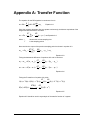
APPENDIX A: TRANSFER FUNCTION.................................................................................77
TelePACE PID Controllers User and Reference Manual
5
TelePACE PID Controllers Overview
The PID (Proportional, Integral, Derivative) control algorithm has been used for feedback
control systems since the turn of the century. Traditionally, pneumatic controllers were used
to perform this algorithm. Though easy to use, they are limited as to the additional functions
that can be performed.
Electronic PID controllers expanded the versatility of the feedback system by incorporating
additional functions into the PID algorithm. The low cost microcomputer expanded the
potential for feedback control immensely, with algorithms limited only by the imagination of
the programmer.
SCADAPack and TeleSAFE controllers employ a firmware PID algorithm that features the
ease of use of the pneumatic controller, with the full control power of a computerized system.
The controllers can service completely the control requirements of many industrial and bench
scale applications. The PID control blocks are not limited to the PID control algorithm. They
also provide ratio control, ratio/bias control, alarm scanning and square root functions.
Control blocks may be interconnected to exchange setpoints, output limits, and other
parameters.
PID control blocks operate independent of application programs. A elaborate control program
need not be written to use the control blocks. A simple program to set up the control blocks is
all that is required.
The main objectives of this manual are presenting how PID and ratio controllers are utilized
in SCADAPack and TeleSAFE controllers, and guiding the user in their application. It is
assumed that the reader already has an understanding of control theory. However, the
rudiments of the PID algorithm are discussed to refresh the memories of experts and to
introduce the concepts for those who are unfamiliar with the PID algorithm. Several
rudimentary control schemes are discussed as well. Two techniques for tuning the PID
controllers are presented. For experienced users, a section on implementing advanced
control algorithms is included.
We have endeavored, as much as is possible, to present a clear, concise guide to the control
blocks in controller. Everyone, including those familiar with other Control Microsystems
products, should read this manual at least once, as concepts unique to the control blocks in
the controller are discussed. New users are encouraged to read the manual twice, so that the
more difficult concepts become clearer. A thorough study of the manual will enable you to
extract the full potential of your controller.
TelePACE PID Controllers User and Reference Manual
6
Introduction to PID Control
An automatic control system regulates a process by manipulating a control element through
the feedback of a controlled output. The common household thermostat is an example of
feedback control. The room temperature is compared to the temperature setting and a
decision is made to turn the furnace on or off. The room temperature is known as the
process value and the temperature setting is known as the setpoint. The furnace, in this
case, is the control element.
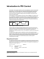
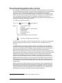
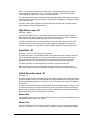
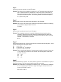
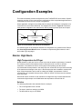
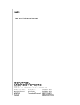
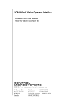
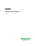
A block diagram of a typical feedback control loop is shown in Figure 1. The setpoint is fed
into a comparator for comparison to the process value. For the household thermostat, the
process value is the temperature of the house. The control algorithm makes the decision and
generates the control output. The process is affected by the control output, resulting in a
change in the process value. Ultimately, the process output will change sufficiently that the
process value will approach the setpoint value.
setpoint
+
–
error
Control
Algorithm
process
value
output
Process
process
value
optional
Figure 1: Typical Feedback Control Loop
Process control in the chemical processing industry has been used since the turn of the
century, but efforts to understand feedback control were not extensive until the 1920's. The
laying of the Trans-Atlantic communications cable necessitated the development of
predictable and reliable transmission control. The foundations of modern control theory were
set in this era.
The product of the original research in transmission control is the Proportional-IntegralDerivative (PID) controller that is now used extensively for industrial feedback control. In this
chapter, the theory of the PID controller is explained. Rather than treating PID as a single
entity, P, PI and PID controllers are discussed to illustrate the effect of each element. The
development of the PID algorithm is explained step by step to provide a general
understanding for the reader.
Proportional Control
The proportional controller produces an output that is proportional to the difference between
the setpoint and the process value. This difference is commonly referred to as the error. The
greater the error, the greater the output of the controller. The equation for the output from a
proportional controller is given as:
m = K × e + ms
where: m
K
e
ms
Equation 1
is the controller output
is the gain
1
is the error = setpoint – process value
is a constant
1
See the Error section on page 23 for a full description of how the error is calculated in the PID
algorithm on the controller.
TelePACE PID Controllers User and Reference Manual
7
The error term is calculated as the difference of the setpoint and the process value. Thus,
these two values must be measured in the same units.
K is the controller's proportional gain. It is the adjustable parameter in the controller that
enables it to be tuned. By adjusting the gain, the magnitude of the control output can be
changed for a given error. The parameter ms is equal to the steady state output required to
produce an error of zero. When the error is zero, it can be seen from equation 1 that the
controller output is necessarily equal to ms. Thus, the steady-state error in a process
controlled by a proportional controller is equal to zero if there are no changes in the process.
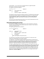
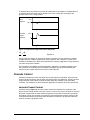
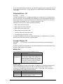
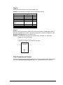
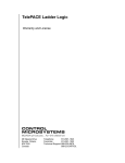
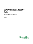
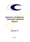
A problem arises with proportional control when a disturbance is introduced to the process.
Disturbances result in a steady-state error (ess) as shown in Figure 2. The best way to
explain the effect of a disturbance is through the following example.
Process
Value
Response
process
value
setpoint
ess
t1
Controller
Output
Response
time
output
ms
t1
time
Figure 2: Proportion Controller Response
Example:
A proportional controller is used to control the temperature of a house. The constant ms has
been chosen so that the house temperature is 21°C. With this value of ms there is no error.
Unfortunately, a window is left open on a winter day. The value of ms is insufficient to keep
the temperature at 21°C resulting in an error. Since it is a proportional controller, the
presence of an error causes the output of the controller to increase by the amount K×e, but
this increase is insufficient to raise the temperature of the house to the setpoint of 21°C.
Thus, a steady-state error results.
Figure 2 shows the process value and the response of a P controller to a disturbance
introduced at time t1. At t1, the process value is equal to the setpoint and the controller output
is ms. The disturbance causes the process value to fall below the setpoint. The resulting time
varying error, causes the controller output to increase. This causes the error to decrease, but
a steady-state error (ess) must persist in order to maintain the increased output of the
controller.
Thus proportional controllers are very sensitive to disturbances, and given sufficient time and
disturbances, a steady-state error will result.
On/Off Control
A special case of the proportional controller is the On/Off controller (sometimes called a
bang-bang controller). As the name implies, there are only two states of the output of an
TelePACE PID Controllers User and Reference Manual
8
on/off controller – on or off. There are no in-between states. The typical household
thermostat is an example of this type of controller.
The equation for the on/off controller is:
m = K × e, K = ∞
where: m
K
e
Equation 2
is the controller output
is the gain = ∞
is the error = setpoint – process value
This equation is similar to that of the proportional controller. The differences are that the gain
is fixed at infinity, and the constant ms is removed (since the term K×e is so large, the term
ms is essentially zero). Therefore, for any negative error (i.e. process value greater than
setpoint) an infinitely negative output results; for any positive error, an infinitely positive
output results.
In the case of the household thermostat, when the room is cold, the thermostat turns on the
furnace and when it is warm, it turns off the furnace.
Proportional-Integral Control
A proportional controller produces a steady-state error when a disturbance is introduced.
This error can be eliminated by adding integral action to the P controller. This is known as
proportional-integral (PI) control.
The equation for the output of a PI controller is:
m=K ×e+
K
e dt + ms
Tò
where: m
K
e
T
ms
ò e dt
Equation 3
is the controller output
is the gain
is the error = setpoint – process value
is the reset time
is a constant
is the integration of all previous errors
The second term in the equation is known as the integral term. The other terms of the
equation are unchanged from the P controller equation.
The parameter T is an adjustable quantity that determines the amount of integral action in
the output of the controller. The parameters K and T allow the PI controller to be tuned. It can
be seen upon inspection of equation 3 that the PI controller becomes a P controller as T
approaches a positive infinite quantity (T cannot be negative since it measures a time
quantity). As T approaches infinity, the integration term in the equation approaches zero.
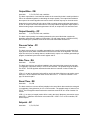
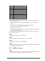
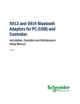
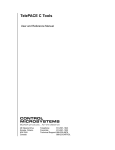
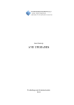
The effect of adding integral action is to remove steady-state error. When an error exists, it is
summed (integrated) with all the previous errors, thereby increasing or decreasing the output
of the PI controller (depending upon whether the error is positive or negative). Thus, as the
error accumulates in the integral term, the output changes so as to eliminate the error. A P
controller will have a constant output when a steady-state error exists, thereby perpetuating
the error. A PI controller reduces the steady-state error to zero, through the action of the
integral term, as shown in Figure 3.
TelePACE PID Controllers User and Reference Manual
9
Example:
The temperature regulation of the house in the previous example can be improved by using a
PI controller. If the window is opened on a cold day, a positive error results between the room
temperature and the setpoint (i.e. the room is cold). The error accumulates in the integration
term and as this term gets larger the output of the controller increases. As a result of the
increase in the controller output, the room temperature increases until the setpoint is
reached.
When the setpoint is reached, the error and all the subsequent errors are zero and the
integration term becomes a constant. PI control has eliminated the steady-state error that
results when a disturbance is encountered by a P controller.
Process
Value
Response
process
value
setpoint
t1
Controller
Output
Response
time
output
ms
t1
time
Figure 3: Proportional-Integral Controller Response
As a further illustration, assume that the window is now closed. Since a source of heat loss
has been eliminated, the temperature rises above the 21°C setpoint producing negative
errors. Summing these negative errors into the integral term decreases the output of the
controller. The temperature then falls until the setpoint is reached, at which point the error
and all subsequent errors are zero. When this occurs, the integral term ceases to decrease
and becomes constant. The output of the controller is constant and the room temperature
remains at the setpoint. Steady-state error has been avoided.
Figure 3 is representative of the typical response of the process and the PI controller to a
disturbance. The steady-state error in Figure 2 is not characteristic of the process response
when regulated by a PI controller.
A novel (though not theoretically correct) way of viewing integral action is that it emulates the
resetting of the setpoint. To see what is meant by this, consider that the occupant of the
house in the previous example has found that the room temperature is below the desired
level. The occupant is a P controller and regulates the temperature. Rather than checking for
an open window, the occupant raises the thermostat setting every five minutes until the
temperature is 21°C. The five minute period is the setpoint reset time, hence the naming of
the parameter T in equation 3. It is important to understand that in a PI controller the setpoint
is not altered. The integral term takes this "setpoint resetting" into account.
TelePACE PID Controllers User and Reference Manual
10
Proportional-Integral-Derivative Control
The response of PI controller tends to be oscillatory. The process value continuously rises
above and falls below the setpoint. This is the result of the integral action over-compensating
for the error. The amplitude of the oscillations can be decreased by decreasing the
proportional gain, K, or by decreasing the amount of integral action by increasing T. This
results in a much slower response of the controller (i.e. a longer time to reach the setpoint
once a disturbance has been introduced). The addition of derivative control to the PI
controller improves the response of the controller when the gain and/or the integral action is
decreased to eliminate the oscillatory response.
The equation for the PID controller is:
m=K×e+
K
dp
+ ms Equation 4
e dt + K × R ×
ò
T
dt
where: m
K
e
T
R
p
ms
is the controller output
is the gain
is the error = setpoint – process value
is the reset time
is the rate gain
is the process value
is a constant
ò e dt
is the integration of all previous errors
dp
dt
is the rate of change of the process value
The third term in the equation is known as the derivative term, as it takes into consideration
the rate of change of the process value. The other terms are unchanged from the PI
controller.
The parameter R is the rate gain. The PID controller can be tuned to give an adequate
response for any process, by adjusting the rate gain, along with the proportional gain and
reset time. The derivative gain is adjusted to vary the magnitude of the output change for a
given change in the process value. R is measured in time units; usually seconds.
2
Derivative (or anticipatory) action detects a change in the process value and produces an
output based upon the change. If the process value suddenly increases, the derivative action
responds to decrease the output of the controller so as to decrease the process value.
Derivative action anticipates a permanent increase or decrease in the process value,
therefore improving the response of the controller by rapidly applying an opposing output.
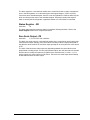
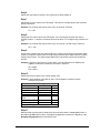
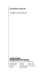
Figure 4 illustrates the response of a PID controller to a disturbance introduced at time t1.
The response is quicker and less oscillatory than that of a PI controller. The peak in the
controller response, known as the derivative peak, is caused by the sudden change in the
process value.
Readers who have previously studied process control theory may have detected that the
derivative term in equation 4 has been subtracted from the equation for the PI controller
rather than added, as is stated in many process control textbooks. It also uses the rate of
change of the process value rather than the rate of change of the error. Textbooks often
state that these two rates are equivalent, but this is not necessarily true.
2
Note that this is not necessarily the same as a change in the error.
TelePACE PID Controllers User and Reference Manual
11
To illustrate this point consider a process at steady-state. If the setpoint is changed there is
an instantaneous and infinite rate of change in the error; but the rate of change of the
process value is zero. Simply stated:
Process
Value
Response
process
value
setpoint
time
t1
Controller
Output
Response
output
ms
time
t1
Figure 4: Proportional-Integral-Derivative Response
de dp
≠
dt dt
Equation 5
during a setpoint change. As a result, the output of equation 4 is less sensitive to setpoint
changes than the equation suggested by many textbooks. Also, equation 4 is much more
sensitive to disturbances in the process, whereas the equation suggested in many textbooks
can make the process unstable.
The Z-transform of equation 4 has been derived in Appendix A. A stability analysis on the
PID controllers of SCADAPack and TeleSAFE controllers must be performed using this
transfer function, rather than the ones cited in most textbooks.
Cascade Control
Cascade controllers are often used when two control loops are interrelated. One of the two
loops is usually fast acting, and the other slow acting with a long dead time. Usually, the slow
acting controller is the primary controller and the fast acting controller is the secondary
controller. Two examples of control situations applicable to cascade control are given below.
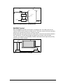
Jacketed Vessel Control
Jacketed vessels (Figure 5) are often used to control the temperature of products. If the
jacket volume is large relative to the tank volume, it may be very easy to overheat or overcool
the jacket contents with the result that the temperature of the tank contents will cycle about
the setpoint. Using one controller to maintain the jacket temperature with the setpoint of the
controller determined by a second product temperature controller is an effective method to
achieve accurate, high speed control.
TelePACE PID Controllers User and Reference Manual
12
vessel
control
valve
steam
heater jacket
process
value
output
Secondary
Controller
temperature
setpoint
process
value
output
Primary
Controller
temperature
setpoint
to condensor
and boiler
Figure 5: Cascade Control of Jacketed Vessel
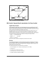
Ball Mill Control
Ball mills (Figure 6) operate best at specific ore loading levels. The loading level can be
measured by the current required to rotate the mill. The motor current is the main controlling
parameter and provides the input to the primary controller.
Weight belts with motor speed controls are often used to control the rate at which material is
fed to the ball mill. The fast acting weigh belt signal forms the input to the secondary
controller. The setpoint in the secondary controller is derived from the output of the primary
ball mill motor current controller.
ball mill
feed belt
belt motor
belt
speed
sensor
motor
output
process
value
Secondary
Controller
setpoint
motor current
sensor
output
process
value
Primary
Controller
setpoint
Figure 6: Cascade Control of a Ball Mill
TelePACE PID Controllers User and Reference Manual
13
Ratio/Bias Control
A ratio/bias controller sets the controller output equal to the input multiplied by a constant,
plus an optional output bias. Ratio controllers are used where an analog output must track an
analog input or output signal.
Ratio/bias controllers can also be used to provide remote setpoint inputs for PID controllers.
Refer to Remote Block Setpoints in the Control Block Setpoint Concepts section for a
description of this capability.
The equation for the ratio/bias controller is:
m = K × p + Bo
where: m
K
p
Bo
Equation 5
is the controller output
is the ratio gain
is the process value
is the output bias
This equation is similar to that of the proportional controller. The difference is that it is the
process value rather than the error (setpoint - process value) which is multiplied by the gain.
The proportional controller will behave as a ratio controller if a negative gain and a setpoint of
zero is used. However, for simplicity, the ratio controller has been incorporated as a separate
entity in TelePACE PID control blocks.
Ratio/bias controllers are typically used to track the output of another controller. To illustrate
this, consider the fuel flow rate to a furnace that is controlled by a PID controller. As more
fuel is added, more air (in direct proportion) is required for combustion. A ratio controller
whose input is the output of the fuel flow controller will add the required air in direct
proportion.
Time Proportioned Outputs
There are two possible types of output from a PID or ratio/bias controller: an analog signal
and a time proportioned digital output (sometimes called a pulse duration output). An analog
output sends the controller output quantity to an analog output module to generate an analog
signal. A time proportioned output sends the controller output quantity indirectly to a digital
output.
Simply stated, for a time proportioned output, the output of a PID controller is used to
proportion a fixed time period into an "on-time" and an "off-time". During the on-time, a digital
output is turned on; during the off-time the output is turned off.
The length of the on-time is proportional to the magnitude of the controller output, while the
off-time is the difference between the fixed time period and the on-time. Consequently, the
time proportioned output is a train of pulses of varying widths where the pulse width
corresponds directly to the controller output.
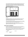
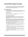
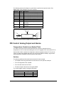
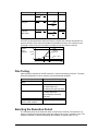
In this way, the output simulates an analog output. Figure 7 compares a time proportioned
pulse train to an equivalent analog output. The width of the pulse is proportional to the height
of the analog output at the start of each time period T.
The control elements that are best suited to time proportioned outputs are devices that can
withstand frequent cycling between the on and off states. Such devices include solenoid
valves controlling continuous flows, forward/reverse motor screws, high power electric
heaters (where SCR controllers might be very expensive), and diaphragm valves with
open/close control solenoids. Although it is possible to use electric motors with this type of
output, excessive wear, caused by the frequent start-ups, may result.
TelePACE PID Controllers User and Reference Manual
14
There are operational limitations involved in using time proportioned control. Since a timer is
used to set the on-time, the resolution of the pulse output is limited by the minimum time
interval of the timer. The resolution can be improved by increasing the length of the fixed
time interval that is being partitioned. The paradox here is that by increasing the fixed time
period, the frequency of execution of the control algorithm is decreased, which can result in
unstable response in extreme cases.
Analog
Output
100%
50%
0%
T
Time
Proportioned
Output
100%
2T
3T
4T
5T
6T
7T
0.0T 0.8T 1.0T 0.9T 0.5T 0.1T 0.0T 0.5
8T
time
0.8T
0%
T
2T
3T
4T
5T
6T
7T
8T
time
Figure 7: Analog and Time Proportioned Outputs
Example
Consider that the temperature of a liquid in a vessel is regulated by a PID controller with a
time proportioned output directed to a solenoid valve that admits steam to a jacket
surrounding the vessel. The timer used to set the output on-time has a resolution of 0.1
second. The fixed time period is 10 seconds.
To illustrate the determination of the on-time consider that the PID controller has calculated
an output of 30. The timer is thus loaded with 30 tenths of a second and since a non-zero ontime is required, the digital output to the solenoid valve is turned on.
After the timer has timed-out (after 3 seconds), the digital output is turned off for the
remainder of the time period, that is 7 seconds. Once this period has passed, the control
algorithm executes again and the cycle repeats.
Square Root Linearization
PID controllers and ratio/bias controllers assume that the process value is linear. Some
methods of measurement product non-linear signals. The output of the measurement device
does not vary in a linear fashion with respect to the quantity being measured.
Consider the control of the flow rate of a liquid. The input to the controller is a height reading
from a manometer (or more commonly a differential pressure cell) installed on the piping. It
can be shown that the flow rate is proportional to the square root of the height of the
manometer. The equation is:
f = K p+C
where: f
K
Equation 6
is the flow rate
is the gain
TelePACE PID Controllers User and Reference Manual
15
p
C
is the process value (reading from manometer)
is a constant adjusting for pump head, NPSH and pipe friction
To use the manometer reading as a process value it must be linearized, by taking the square
root, before the calculations of the PID controller or the ratio/bias controller can be
performed. TelePACE PID controller blocks provide a square root extraction function for this
purpose. If it is necessary to specify the constant C, the control blocks provide an input bias
for this purpose.
An inherent problem with this linearization is that the precision of the process value is no
longer linear over the range of the process value. The larger the process value, the more
precise the result of the linearization.
Square Root Normalization
The normal input range of the process value in TelePACE PID control blocks is –32767 to
32767 I/O counts. If square root extraction is performed on this range, a maximum value for
the process value of 181 results. Since this effectively reduces the resolution (though not the
precision) of the input, TelePACE PID control blocks normalize the square root value, by
multiplying it by 128. Thus the square root of 32767 (181) becomes 23170.
The control blocks retain the sign of the value when a square root is extracted, and calculate
the root on the magnitude of the value. This allows square root extraction on inputs whose
values may be negative.
TelePACE PID Controllers User and Reference Manual
16
Introduction to Control Blocks
TelePACE PID control blocks are capable of providing the following functions, or
combinations of functions:
• P, PI, PID or PD control
• multi-loop cascade control
• on/off control
• ratio control
• ratio/bias control
• square root extraction
• alarm detection with annunciation
A control block may be configured to perform any of the above operations. Some
configurations permit multiple functions within a block. For instance, only one block is
required for a PID controller with square root extraction and alarm level detection on the
process value. Other combinations are possible.
Blocks may be interconnected to combine their functions in a larger control scheme. For
instance, multi-stream blending control can use one PID controller to control total stream flow
with any number of slave ratio controllers to control the flow contributed by each stream. The
same system could use other blocks to detect alarm levels on either controller outputs or
stream flows; or to turn stream pumps on or off.
An important aspect of the control blocks is that they operate in the background, independent
of application programs. However, application programs have full access to all block
parameters and tuning parameters at any time. This permits advanced control concepts such
as dynamic tuning. Programs written in C or Ladder Logic can supervise control loops to
optimize their operation. In fact, application programs can even reconfigure the blocks during
operation. For example, controllers can be set up to operate as proportional-only controllers
when the error is large, and then be reconfigure to PI controllers when the error becomes
smaller. This interaction between the program and the control blocks provides a very high
degree of flexibility.
Control Block Characteristics
The sections below describe the main features of the TelePACE PID control blocks.
Background Operation
Control blocks operate in real time, separate from application programs. This ensures that
time critical operations receive priority. Blocks can be set up to operate on individual time
intervals. High speed control loops can be serviced more frequently than slower loops so as
to distribute processor power where it is required. Control blocks will operate even when
programs are being edited
TelePACE PID Controllers User and Reference Manual
17
Independent Sample Times
Control blocks may be individually configured for ten executions per second to as few as one
execution every 6553.5 seconds. Longer sample times consume fewer processor cycles,
leaving more time available to application programs.
Application Program Access
Application programs may read all control block tuning parameters and internal variables,
even when the controllers are executing. Likewise, a program may store tuning parameters
and internal variables into the controllers. This feature permits dynamic tuning of controllers
during operation.
Anti-Integral Windup
Anti-integral windup prevents integral summation (reset operation) if the outcome of such
summation would be to set the controller output above or below the defined output limits.
Output Limiting
Output limits may be programmed for each controller to prevent the controller from
generating an output that is above or below desired limits.
Square Root Extraction
Controllers may be configured to calculate the square root of the process value and/or the
error. The sign (polarity) of the process value and/or error is retained. Square roots are
useful when the process value is derived from orifice-plate flow meters or other devices
which exhibit a square relationship.
External Execution Inhibit
Each controller may use a digital input from the I/O system to prevent execution of the
controller. The controller will halt execution as long as the input remains on.
Automatic Alarm Scanning
A feature included in the control blocks (which is not related to the control algorithm) allows
analog input channels to be monitored for levels above or below alarm limits, with a digital
output turning on if an alarm condition exists. The digital address that turns on may be an
interrupt input which will cause an immediate interrupt under alarm conditions.
Deadband
A programmable deadband allows the PID controller algorithm to do a partial execution
without changing the output if the absolute value of the error is less than or equal to the
deadband. This partial execution is much faster than a full execution. It also prevents excess
cycling of control elements, thereby reducing wear.
TelePACE PID Controllers User and Reference Manual
18
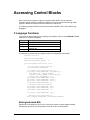
Accessing Control Blocks
Each control block contains of a group of registers which define, tune and provide
information about the block. Application programs access the control block through these
registers. Additional functions control the execution of the blocks.
The following sections describe the access functions available in the C and Ladder Logic
languages.
C Language Functions
There are four library functions for accessing control blocks. Refer to the TelePACE C Tools
manual for a complete description.
Function
set_pid
get_pid
auto_pid
clear_pid
Description
set a block variable to a specified value
return the value of a block variable
set a block to execute automatically at the
specified rate
set all block variables to zero
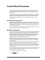
The following C program shows a typical method of configuring a control block.
#include <ctools.h>
#define FLOW_CONTROLLER 0
#define FLOW_CONTROL_PERIOD
10
void configureFlowController( void )
{
/* Clear control block variables */
clear_pid(FLOW_CONTROLLER);
/* Configure block characteristics */
set_pid(CR, FLOW_CONTROLLER, PID_ANALOG_OP |
PID_ANALOG_IP | PID_SP_NORMAL |
PID_PID | PID_NO_ALARM | PID_NO_ER_SQR |
PID_PV_SQR | PID_MODBUS_IO );
set_pid(IP, FLOW_CONTROLLER, 30008);
set_pid(IO, FLOW_CONTROLLER, 40014);
set_pid(FS, FLOW_CONTROLLER, 32767);
set_pid(ZE, FLOW_CONTROLLER, 0);
/* Configure tuning parameters */
set_pid(GA, FLOW_CONTROLlER, 340);
set_pid(RE, FLOW_CONTROLLER, 470);
set_pid(RA, FLOW_CONTROLLER, 0);
set_pid(SP, FLOW_CONTROLLER, 2000);
/* Execute block automatically */
auto_pid(FLOW_CONTROLLER, FLOW_CONTROL_PERIOD);
}
Setting Individual Bits
Sometimes it is desirable to turn on a bit or bits in the control or status registers without
affecting any other bits. The OR operator is used to do this, as shown below.
TelePACE PID Controllers User and Reference Manual
19
int i;
i = get_pid( CR, x ) | 0x08; /* set bit 3 */
set_pid( CR, x, i );
/* save new value */
Clearing Individual Bits
Sometimes it is desirable to turn off a bit or bits in the control or status registers without
affecting any other bits. The AND operator is used to do this, as shown below. The value
used with the AND operator has all bits on, except the ones that are to be cleared.
int i;
i = get_pid( CR, x ) & 0xF8; /* clear bits 0,1,2 */
set_pid( CR, x, i );
/* save new value */
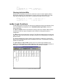
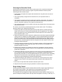
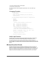
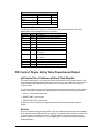
Ladder Logic Functions
A ladder logic program accesses all control block variables through the I/O database. Refer
to the I/O database documentation in the TelePACE Ladder Logic Editor manual for
register addresses.
The PUT and PUTU functions are suitable for writing to the block variables. Both functions
can write one value to a group of registers; this is useful for clearing a block prior to
configuration.
The PID function controls execution of a block. The PID block starts execution on the rising
edge on the input to the PID function and stops execution on the falling edge of the input to
the PID function.
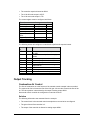
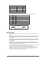
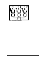
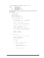
The following ladder logic program shows a typical method of configuring a control block.
Note that the first PUTU function clears all variables in the block. The subsequent functions
initialize the parameters.
The pid 0 setup and pid 0 enable contacts come from control logic elsewhere in the
program. The setup contact is normally triggered by a one shot coil on the first execution of
the program. The enable contact turns on when the PID controller is required.
TelePACE PID Controllers User and Reference Manual
20
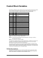
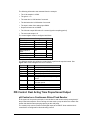
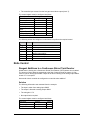
Control Block Variables
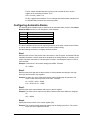
Control block variables are used to define and to tune the control blocks. Each block contains
a set of variables. The following list shows the valid variable names, the range of valid
values, and a brief description. A complete description of the variables follows.
Variable
AO
CA
Range
3
3
CR
DB
DO
ER
FS
GA
HI
IB
IH
IN
IO
IP
LO
OB
OP
PV
RA
RE
SP
SR
ZE
3
3
3
1
1
2
1
1
3
2
3
1 or 3
1
1
1
1
1
1
1
1
1
Description
alarm output address
cascade setpoint source block
number
block control register
deadband
decrease output address
PID error
full scale output (high limit)
gain
high alarm level
block input bias
inhibit execution input address
integrated error total
increase output address
block input source
low alarm level
block output bias
block output quantity
process value
rate time (in 0.1 second increments)
reset time (in 0.1 second increments)
controller setpoint
block status register
zero scale output (low limit)
Range 1 is an integer in the range –32768 to 32767.
Range 2 is a fixed point integer with two fixed decimal places. The range is –32768 (=–
327.68) to 32767 (=327.67).
Range 3 is an integer in the range 0 to 65535.
The range does not indicate that any number that falls within it is suitable for the function of a
controller. It only indicates the maximum and minimum values that can be used without
generating an error and the accuracy of the representation.
For maximum execution speed, the control block algorithms operate on unscaled numeric
quantities rather than engineering unit quantities. When a datum such as a setpoint is stored
in a block, it must be stored in units that are acceptable to the algorithms. This usually means
conversion from engineering units to 16 bit signed integer.
Variable Descriptions
A description of the function and use of each block variable is given in this section. Not all
variables are used with all configurations of a control block. The applicable block types are
listed for each variable. The variables are listed in alphabetic order.
TelePACE PID Controllers User and Reference Manual
21
Alarm Output Address - AO
Used with: alarms
The block alarm output address is a user defined variable which specifies the alarm output
address. When a high or low alarm is detected, the digital output address specified in AO will
be turned on if the block control register enables the alarms. For more information, see the
Status Register section describing the alarm acknowledge bit of SR.
Method One
If the I/O Specification bit in the control register is set to 1, AO may contain the address of
any valid Modbus coil register. (e.g. 00014).
Method Two
If the I/O Specification bit in the control register is cleared to 0, AO must contain an absolute
address which is calculated as: channel * 8 + bit. Therefore to use channel 5, bit 3 as the
alarm output, AO would be defined as 5 * 8 + 3 = 43. The absolute address method is only
valid if the Default Register Assignment Table is downloaded to the controller, or if the
controller is a TeleSAFE Micro16 with firmware version 1.22 or older.
Cascaded Setpoint Source - CA
Used with: P, PI, PD, PID
The cascaded setpoint source block is a user defined variable in the control block that
defines the source of cascaded setpoints for secondary cascaded controllers. It contains the
block number whose output OP, will provide the setpoint for the PID controller. The output
from the block specified in CA becomes the setpoint of the secondary cascaded controller.
The block cascade setpoint is only used by the control block when the block control register
is configured as a P, PI, PID controller with setpoint from block CA.
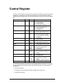
Control Register - CR
Used with: all
The block control register determines the function of the block. Refer to the Control
Register section for a complete discussion.
Deadband - DB
Used with: P, PI, PD, PID
The block deadband is a user defined variable in the control block that is used by the PID
algorithm to determine if the process requires control outputs. If the absolute value of the
block error is less than the block deadband, then the block skips execution of the control
algorithm. This permits faster execution when the error is within a certain acceptable range
or deadband.
To make the block perform a complete execution even on the smallest measurable error the
block deadband should be set equal to 0.
To minimize background overhead, PID type blocks should use a reasonable value of
deadband. Blocks execute up to five times faster if the error is within the deadband.
Decrease Output - DO
Used with:
P, PI, PD, PID, ratio, ratio/bias blocks with time proportioned outputs
TelePACE PID Controllers User and Reference Manual
22
The block decrease output address is a user defined variable in the control block that is used
to define a pulse duration or motorized pulse duration output. When the block output, OP is
negative, the digital output at DO is turned on for a length of time (in tenths of a second)
equaling the absolute value of the block output. If the block output is positive, the digital
output at DO is turned off.
Method One
If the I/O Specification bit in the control register is set to 1, DO may contain the address of
any valid Modbus coil register. (e.g.
Method Two
If the I/O Specification bit in the control register is cleared to 0, DO must contain an absolute
address which is calculated as: channel * 8 + bit. For example, bit 7 of channel 13 will equal
13 * 8 + 7 = 111. The absolute address method is only valid if the Default Register
Assignment Table is downloaded to the controller, or if the controller is a TeleSAFE Micro16
with firmware version 1.22 or older.
Error - ER
Used with: P, PI, PD, PID
The block error is a variable generated by the control block that contains the process error
from the most recent calculation. The initial calculation is
ER = SP – PV
If the absolute value of the error is less than the deadband, no further calculation is done and
the output of the block does not change.
If the absolute value of the error is equal to or greater than the deadband, then the error is
calculated using the formulae below.
ER = SP – PV + DB if the PV is greater than setpoint
ER = SP – PV – DB if the PV is less than the setpoint
This calculation ensures there is no large jump in the error, and a corresponding process
disturbance when the process comes out of the deadband.
Full Scale Output - FS
Used with: P, PI, PD, PID, ratio, ratio/bias
The block full scale output is a user defined variable in the control block used in limiting the
maximum block output. If the control block calculates a block output quantity that is greater
than the value stored in FS, the block output quantity OP is set equal to the value stored in
FS.
The units of the block full scale output vary depending whether the control block is time
proportioned or analog output. For time proportioned outputs, the units are tenths of seconds
and the value is usually set equal to or less than the block execution time. For analog
outputs, the integer is stored in I/O units (-32767 to 32767). The block full scale output
should always be greater than the block zero scale output.
Gain - GA
Used with: P, PI, PD, PID, ratio, ratio/bias
TelePACE PID Controllers User and Reference Manual
23
Gain is a user defined variable in the control block. It is the proportional gain if the block
control register is configured as a P, PI, PD, or PID controller. It is the ratio if the block
control register is configured as a ratio or ratio/bias controller.
The value stored in the gain is a 2 decimal place fixed point integer. Since there is no actual
decimal point, the value stored in the gain is 100 times the actual gain. For example a gain of
1.50 is stored as 150.
A positive value of gain configures a forward-acting PID controller and a negative value of
gain configures a reverse acting controller.
High Alarm Level - HI
Used with: alarms
The block high alarm level is a user defined variable in the control block that indicates at
what value the high alarm is triggered. If the block process value PV exceeds or equals the
value stored in HI then the digital output specified in AO is turned on.
The block high alarm level is normally specified in the units of the process value PV. The
alarm will only be announced if the block control register is configured for alarms active.
If neither a low alarm nor a high alarm exists, the output specified in AO will be turned off.
Input Bias - IB
Used with: P, PI, PD, PID, alarms, ratio, ratio/bias
The block input bias is a user defined variable in the control block that is used by either the
PID or the ratio/bias algorithm to cancel true-zero offset in the input signal to the control
block. The value stored in IB is subtracted from the block input before any of the block
algorithms execute. The quantity stored in PV already has the input bias subtracted.
The block input bias is usually expressed in the units of the process value PV.
Block input bias can be useful in calibrating input signal sources by storing the actual
instrument reading into the input bias under conditions of known true zero process signals.
Inhibit Execution Input - IH
Used with: all
The block inhibit execution input address is a user defined variable in the control block which
specifies a digital input bit. It is used to disable or enable the automatic execution of a control
block depending upon whether a control bit is on or off. A value of zero stored in IH disables
this function.
The block will be prevented from executing whenever the bit whose address is stored in IH is
on. When the bit turns off, execution will resume, but the resumption will not be bumpless. If
the block input changes during the period execution is inhibited, the change will immediately
appear at the block output on resumption of execution.
Method One
If the I/O Specification bit in the control register is set to 1, IH may contain the address of any
valid Modbus status register (e.g. 10023).
Method Two
If the I/O Specification bit in the control register is cleared to 0, IH must contain an absolute
address (i.e. channel * 8 + bit). Channel 0, bit 0 cannot be used as a valid absolute address
TelePACE PID Controllers User and Reference Manual
24
for IH. The absolute address method is only valid if the Default Register Assignment Table is
downloaded to the controller, or if the controller is a TeleSAFE Micro16 with firmware version
1.22 or older.
Integrated Error - IN
Used with:
PI, PID
The block integrated error is a variable generated by the control block if it is configured as a
PI or PID controller. The value stored in the integrated error is a 2 decimal place fixed point
integer. Since there is no actual decimal point, the value stored is 100 times the actual error.
For example an integrated error of 71.02 would be stored as 7102.
Changes to IN will not occur under the following conditions:
• Block output tries to exceed FS
• Block output tries to drop below ZE
• Block reset time is equal to zero
• Block inhibit execution input is ON
• The block integral is greater than 32767
• The block integral is less than –32768.
The first two conditions are known as integral anti-windup. The integrated error in a control
block can be set to zero by storing 0 in the IN register.
Increase Output - IO
Used with:
outputs
P, PI, PD, PID, ratio, ratio/bias blocks with analog or time proportioned
The block increase output address is a user defined variable in the control block that is used
to define a block output point as follows:
Method One
If the I/O Specification bit in the control register is set to 1.
Output Type
Analog
time
proportioned
Function of IO
IO contains a valid Modbus holding register.
IO contains a valid Modbus coil register.
When the block output, OP is positive, the
digital output at IO is turned on for a length
of time (in tenths of a second) equaling the
block output. If the block output is negative,
the digital output at IO is turned off.
Method Two
If the I/O Specification bit in the control register is cleared to 0. This address method is only
valid if the Default Register Assignment Table is downloaded to the controller, or if the
controller is a TeleSAFE Micro16 with firmware version 1.22 or older. This is included to
provide backward compatibility for older controller.
Output Type
Analog
time
proportioned
Function of IO
IO contains the analog channel number.
IO contains an absolute digital address
calculated as channel * 8 + bit.
TelePACE PID Controllers User and Reference Manual
25
Input Source - IP
Used with:
all
The block input source is a user defined variable in the control block that is used by the
control block to determine the source of the process value. The process value for the control
block is taken from the source specified in IP.
The value in IP is dependent upon the configuration of the block input in the control register
(see the Control Register section).
Method One
If the I/O Specification bit in the control register is set to 1.
Block Input
None
analog
block output
Function of IP
IP contains the process value. This is useful
in running simulations.
IP contains the Modbus input or holding
register from which the process value is
expected. This is the most often used
configuration of a PID controller's process
value.
IP contains the control block number from
whose output the process value is taken.
Method Two
If the I/O Specification bit in the control register is cleared to 0. This address method is only
valid if the Default Register Assignment Table is downloaded to the controller, or if the
controller is a TeleSAFE Micro16 with firmware version 1.22 or older. This is included to
provide backward compatibility for older controller.
Block Input
none
analog
block output
Function of IP
IP contains the process value. This is useful
in running simulations.
IP contains the analog channel from which
the process value is expected. This is the
most often used configuration of a PID
controller's process value.
IP contains the control block number from
whose output the process value is taken.
Low Alarm Level - LO
Used with:
auto alarms
The block low alarm level is a user defined variable in the control block that indicates at what
value the low alarm is triggered. If the block process value PV is less than or equal to the
value stored in LO then the digital output specified in AO is turned on.
The block high alarm level is normally specified in the units of the process value PV. The
alarm will only be announced if the block control register is configured for alarms active.
If neither a low alarm nor a high alarm exists, the output specified in AO will be turned off.
TelePACE PID Controllers User and Reference Manual
26
Output Bias - OB
Used with:
P, PI, PD, PID, ratio, ratio/bias
The block output bias is a user defined variable in the control block that is used by either the
PID or the ratio/bias algorithm in calculating the output quantity. The output bias is added to
the output of the control algorithm and can be used to shift the output up or down the scale.
Output bias is useful with 4-20 mA outputs. With an analog output module that generates 020 mA, an output bias of 6553 will ensure a 4 mA output when the algorithm output equals 0.
With an analog output module that generates 4-20 mA, an output bias of 0 should be used.
Output Quantity - OP
Used with:
P, PI, PD, PID, ratio, ratio/bias
The block output quantity is a variable generated by the control block that contains the
algorithm output after the addition of output bias. It is a full range integer (–32768 to 32767)
but is limited by the quantities stored in the zero scale ZE and the full scale FS.
Process Value - PV
Used with:
all
The block process value is a variable generated by the control block that contains the block
input (process value) which existed at the most recent execution of the algorithm. The block
input can come from an analog channel, another block's output, or a constant generated by a
program, as defined by the block control register and IP.
Rate Time - RA
Used with:
PD, PID
The block rate time is a user defined variable in the control block that controls the rate gain
(or magnitude of derivative action) in a PD or PID controller. The possible range of values is
0 to 32767. The PID algorithm assumes that the rate time is stored in units of tenths of a
second.
If RA = 0, no rate (or derivative) action will be used in the block. Maximum rate action occurs
when RA = 32767. Minimum rate action occurs when RA = 1. To make a controller P or PI
type, RA should equal 0.
Reset Time - RE
Used with:
PI, PID
The block reset time is a user defined variable in the control block that controls the reset gain
(or magnitude of integral action) in a PI or PID controller. The possible range of values is 0 to
32767. The PID algorithm assumes that the reset time stored in RE is in units of tenths of a
second.
If RE = 0, no reset (or integral) action will be used in the block. Maximum reset action occurs
when RE = 1. Minimum reset action occurs when RE = 32767. For P or PD controllers, RE
should equal 0.
Setpoint - SP
Used with:
P, PI, PD, PID
TelePACE PID Controllers User and Reference Manual
27
The block setpoint is a user defined variable in the control block that is used to calculate the
error in the PID algorithm. It is a dimension-less 16-bit signed integer (–32767 to 32767).
If the block has a cascaded setpoint, then SP is not user definable, but will be defined by the
block and will equal the value of the cascaded setpoint. SP always contains the setpoint
which is used by the block algorithm, regardless whether it is user defined or cascaded.
Status Register - SR
Used with:
all
The block status register reports the status of conditions affecting the block. Refer to the
Status Register section for a complete discussion.
Zero Scale Output - ZE
Used with:
P, PI, PD, PID, ratio, ratio/bias
The block zero scale output is a user defined variable in the control block used in limiting the
minimum block output quantity. If the control block calculates a block output quantity that is
less than the value stored in ZE, the block output quantity OP is set equal to the value stored
in ZE.
The units of the block zero scale output vary depending whether the control block is time
proportioned or analog output. For time proportioned outputs, the units are tenths of seconds
and the value is usually set equal to the negative block execution time (i.e. time x –1). For
analog outputs, the value is stored in I/O counts. The block zero scale output should always
be less than the block full scale output.
TelePACE PID Controllers User and Reference Manual
28
Control Block Input Concepts
All control blocks require an input. This input can be an output of another control block, an
analog signal from a process sensor, or a constant. The block variable IP specifies the input
source, according to the type of input defined by the block control register (see the Control
Register section).
• If the input is a constant, the constant is directly stored in IP.
• If the input is an analog signal, the address of the Modbus input register is stored in IP.
• If the input is taken from the output of another control block, the block number is stored in
IP.
Input limits for constants and analog signals –32767 to 32767. A block input derived from the
output of another block is limited by the output range limits ZE and FS of the block supplying
the output.
Constant Block Inputs
A constant block input is generated by a application program. Constant block inputs are
defined by setting bits 2 and 3 of the block control register to zero. The input value is
specified by storing the value in the IP register.
Process simulation and special input signal conditioning are the usual applications for
constant inputs.
Process Simulation
A model of a process can be derived and programmed. The model supplies all block inputs
to the control blocks by declaring IP = model output. Inputs to the model are derived from
control block outputs, OP.
Signal Conditioning
Input signal conditioning is often used where the instrumentation signal source has a nonlinear relationship, other than a square root relationship, to the real process value. It can also
be used to average several analog input readings, or to provide filtering of the raw process
value in noisy environments.
Example
The process value for block 8 is to be obtained from the average of the three analog inputs at
registers 30001, 30002 and 30003. This application might be useful in the temperature
control of a large vessel, where multiple temperature probes are used.
In a C application program the following statement is used.
set_pid( IP, 8,
(dbase(30001)+dbase(30002)+dbase(30003))/3);
Analog Block Inputs
An analog block input is read from an analog I/O channel. The block variable IP holds the
Modbus address of the analog channel. The channel may be either an input channel or an
output channel. To enable analog channel block inputs, bit 2 of the control register CR should
TelePACE PID Controllers User and Reference Manual
29
be 0 while bit 3 should be 1. The analog channel will be read each time the block algorithm
executes.
Input Channel Block Inputs
Block inputs from analog inputs are most commonly used with feedback control. The process
signal is obtained from an instrument such as a temperature transmitter whose output is
connected to an analog input module.
Another common application for analog block inputs is in the generation of remote setpoints.
In this application a ratio/bias block reads the analog input channel where the remote
setpoint is connected. The ratio block output is usually configured as an internal output where
it can be cascaded into the setpoint of the other controller.
Output Channel Block Inputs
Block inputs from analog outputs are most commonly used with ratio/bias blocks. For
example, a fuel/air ratio control system could use a PID controller to regulate the fuel flow
with a 4-20 mA control valve. A ratio controller can get its input from the PID controller analog
output. The ratio block output could drive air control dampers (open loop), or could provide
the cascaded setpoint for a PID controller on the air control system (closed loop).
Block Output Block Inputs
Block output block inputs is a confusing name for a simple concept. A control block can
receive it's input directly from the output of another block. This is used most commonly with
ratio/bias controllers. Applications include blending control, and output tracking.
Stream Blending Control
In a typical multiple stream blending control system, one PID controller monitors the total
stream flow. The output of this controller can be read by any number of ratio/bias blocks to
obtain the flow setpoint for each of the individual streams. The example for Batch Control
describes the configuration of a complex multiple stream blending control system.
Output Tracking
In a previous example we described a fuel/air control system wherein the air flow setpoint is
derived from the fuel flow analog output. Another way of obtaining the same function is to
have the air controller read the output of the fuel controller directly; not the fuel control analog
output. This configuration is somewhat faster since blocks can get their inputs faster from
block outputs than from analog channels.
TelePACE PID Controllers User and Reference Manual
30
Control Block Output Concepts
At the conclusion of execution, the control block algorithm generates a numeric quantity that
is stored in the block variable OP. This quantity is the block output. The block output can be
directed to one of several destinations, depending upon the requirements of the control
algorithm. Limits may also be applied to the output value.
Block Output Types
A control block always store it's output in the block variable OP. This value may be accessed
by an application program, or by a control block for a cascaded setpoint. The output can also
be directed to analog outputs, time proportioned outputs or dummy analog outputs.
Analog Outputs
The output of the controller is sent to an analog output channel. This output is commonly
used with 4-20 mA control valves and 0-10V recorders.
Time Proportioned Outputs
A block output may be used to control a on/off control elements with a time proportioned
output (also known as a pulse duration output). The value of OP determines the length of
time a digital output will be turned on. The output is turned off for the remainder of the
execution period.
Two types of time proportioned outputs are available; pulse duration and motor pulse
duration. Pulse duration outputs are used with elements such as solenoid values, motors and
electric heaters that must be cycled to maintain a setpoint. Motor pulse duration outputs are
used with motors that must be shut off when a setpoint is reached, such as a positioning
motor. The differences in operation are explained below.
A control block with time proportioned outputs operates identically to an analog output or
cascade output controller up until the point where the output has been calculated. At this
point, the algorithm performs one of four actions:
1. If the control block type is motor pulse duration and the error is within the deadband, both
the DO and IO outputs are turned off. The control block timer is set to zero.
2. If the output is zero, both the DO and IO outputs are turned off. The control block timer is
set to zero.
3. If the output is negative, the DO output is turned on, the IO output is turned off, and the
absolute value of the controller output quantity is will be loaded into a timer. When the
timer reaches zero, the DO output is turned off.
4. If the output is positive, the IO output is turned on, the DO output is turned off, and the
absolute value of the controller output quantity is will be loaded into a timer. When the
timer reaches zero, the IO output is turned off.
The output on-time period is equal to the controller output quantity and is measured in tenths
of a second.
TelePACE PID Controllers User and Reference Manual
31
Choosing the Execution Period
Several factors influence the choice of the execution period of a control block with a time
proportioned output. There must exist a good compromise between execution period,
controller gain and controller output.
• Control blocks will update the outputs and reload the timer only after each execution of
the controller.
• If the output quantity is larger than the execution time, the output will remain on
constantly.
• The longer the execution period, the greater the resolution of the output. For instance, if
the controller executes once every ten seconds, with an interval time of one tenth of a
second, it will yield a resolution of one part in one hundred (1%).
• If the execution period is too long relative to the process response time, the process value
may under/over shoot.
The choice of an execution period depends on the process under control. The following
procedure will aid you in determining the period.
1. Declare high and low output limits equal to the execution period. This will prevent the
output from turning on for a time period greater than the loop update time. For instance,
with an execution time of ten seconds set the full scale output FS to 100, and the zero
scale output ZE equal to –100.
2. Experiment with the process to determine at what process value the outputs should begin
cycling on/off. For example in a heating system, it may be determined that from the time
the heat is turned off, the process temperature will increase three more degrees over a
period of several minutes. This would indicate that the heat should start cycling when the
process value is somewhat greater than three degrees below the setpoint. Assume that
six degrees will be adequate.
3. Convert the process units into I/O units. For example consider a 4-20 mA input with a 0100 degree calibration. Each degree will equal 262.136 counts in I/O quantities. Six
degrees will yield 1573 counts.
4. Determine the maximum loop update time taking into consideration process response
time and desired output resolution. Assume in our example that a ten second execution
update time is adequate.
5. Calculate the PID gain to yield an output time period equal to the loop update period at the
error at which the output should begin cycling. In our example, the gain should equal
approximately 100 tenths of a second update divided by 1573 counts for 0.06. Calculating
the gain thus ensures that the output will begin cycling at the determined temperature.
The gain can then be adjusted to yield the best performance.
6. When determining the gain estimate, err on the low side. This will result in the output
cycling too early. Gains on time proportioned output controllers will usually have low
values.
7. Do not use an output bias. Bias should be declared equal to zero.
8. Keep the execution period as long as possible for maximum output resolution.
Single Acting Control
A time proportioned output controller activates either the DO or the IO output depending on
the controller output polarity. If the output limits as determined by ZE and FS are
appropriately programmed, either output can be prevented from turning on.
The controller can be configured for single acting control in either direction. Referring to our
previous example of heating control, the loop can be configured to cool only, or heat only. To
TelePACE PID Controllers User and Reference Manual
32
define a controller in which only the IO output will turn on, the output limit ZE should be
programmed at zero. Preventing the output from going negative ensures that the DO output
will never turn on.
Dual Acting Control With 2 Controllers
Sometimes, dual acting control elements exhibit significantly different response
characteristics. A dual acting controller can be optimized for each control element by using
two, single acting time proportioned output controllers which are individually tuned. The
controllers will be tuned in the normal fashion but the following points should be noted:
• Both blocks should have the same setpoint so that they do not activate the control
elements in opposition.
• Both blocks should use a deadband to minimize the probability of output opposition due to
different reset action.
• Both blocks should use the other's output as an inhibit execution input. This will prevent
the block from executing (and maybe turning on its output) if the other block's output is
on.
Dummy Analog Outputs
A dummy analog output is a Modbus holding register which has not been assigned to an
output module. Such a register is also called a general purpose holding register. The output
of the block is stored in the holding register where it can be accessed by other blocks or
application programs. Dummy analog outputs are configured in exactly the same fashion as
true analog outputs.
Output Limiting
The range of the block output is defined by the full and zero scale output limits. The limits
allow the user to restrict the range of analog outputs, cascade setpoints, and the maximum
and minimum on-time of time proportioned outputs. This is useful when the full range of
operation of control devices could result in damage to the process or excess product being
produced.
Zero Scale Output Limit
The zero scale (or minimum) output limit is determined by the quantity which is stored in the
block variable ZE. The block output is allowed to go as low as the quantity stored in ZE, but
no lower. A negative quantity is permitted in some circumstances as explained below. The
zero scale limit should always be less than the full scale limit, or indeterminate operation will
result.
Full Scale Output Limit
The full scale (or maximum) output limit is determined by the quantity which is stored in the
block variable FS. The block output is allowed to rise up to and equal the value stored in FS,
but not to exceed it. The full scale limit should always be greater than the zero scale limit
value, or indeterminate operation will result.
Analog Block Output Limits
Analog output limits prevent the output signal from exceeding pre-defined limits. This is
particularly useful with 4-20 mA analog outputs. The I/O system is capable of generating 0-20
TelePACE PID Controllers User and Reference Manual
33
mA outputs. By setting the zero scale limit to 6553, the output is prevented from dropping
below 4 mA. The quantity 6553 is obtained by scaling the 0 to 32767 I/O count output to mA:
ZE =
4mA
× 32767 = 6553
20mA
The analog output system uses 16-bit signed numbers; thus the analog output range is 0 to
32767. The I/O system only permits positive polarity analog outputs. If ZE is less than 0 the
output will be clamped at 0. If FS is greater than 32767, the output will be clamped to 32767.
Time Proportioned Output Limits
The block output value determines two factors for time proportioned outputs: which of the
increase or decrease outputs is turned on; and the time period for which it is turned on. If the
block output is negative, the decrease output, DO, will turn on and the increase output, IO,
will turn off. If the block output is positive, the increase output, IO, will turn on and the
decrease output, DO, will turn off. If the output is zero, both outputs will be turned off. Dual
outputs such as this are usually referred to as double acting.
The output limits can be used to prevent one of the outputs from turning on, thereby
providing the controller with a single acting output. If ZE is set to zero, output DO cannot turn
on as the block output will never be negative.
The output limits can also be used to limit the on-time of an output. The on-time is equal to
the block output value. ZE and FS set the maximum value of this time period, for decrease
outputs and increase outputs respectively. The block output limits should be set equal to the
execution period of the block if no limiting is desired.
See the Time Proportioned Outputs section above for more information.
Dummy Analog Output Limits
Dummy analog channel block outputs behave identically to standard analog outputs. Since
the I/O system does not permit bipolar analog outputs, the block output is restricted to the
range 0 to 32767. Setting the zero scale limit to a negative quantity will have no effect; the
minimum output will be clamped at zero.
Internal Block Output Limits
An internal block output may be bipolar. The zero scale limit may therefore be set to a
negative value.
TelePACE PID Controllers User and Reference Manual
34
Control Block Setpoint Concepts
The block setpoint is the desired value of the process value. The source of the setpoint, SP
can be a constant or the output of another control block (cascaded setpoint). Setpoints can
also be obtained from a remote source through an analog input or ramped by an application
program.
Constant Setpoints
A constant setpoint is generally set by an operator, although it can be generated by an
application program. It is stored in the SP register by an application program, or through the
I/O database. A constant setpoint is configured by clearing bit 4 of the block control register
(CR).
C application programs store the setpoint with the set_pid function or by writing to the I/O
database with the setdbase function.
Ladder logic programs store the setpoint with a PUT, PUTU, or other register transfer
function.
A host computer stores a setpoint by writing to the appropriate register in the I/O database.
Refer to the C or ladder logic user manual for details on the I/O database.
Cascaded Setpoints
A cascaded setpoint comes from the output of another control block. The source is set by
storing the block number of the primary block in the CA register. A constant setpoint is
configured by clearing bit 4 of the block control register (CR) in the secondary (destination)
control block.
Example:
Control block 1 is used as the primary controller and control block 2 is used as the secondary
controller in a cascade configuration. The value stored in CA of block 2 is 1 and bit 4 of this
control register must be set. Once both control blocks are in operation the setpoint of block 2
will be equal to the output of block 1.
Remote Block Setpoints
Remote setpoint controllers derive their setpoint from an external device rather than direct
programming or cascade control. For instance, a potentiometer may be the best method of
allowing an operator to change the setpoint. Or, a high speed hardware controller may pass
it's output into the setpoint of a TelePACE PID control block. The latter is an example of
cascade control where the primary controller is external hardware and the secondary control
is provided by the controller.
Remote setpoints are best implemented using the following technique:
• Define a ratio/bias controller to read the analog input.
• Cascade the output of the ratio/bias controller into the setpoint of a second control block.
• Both controllers must have the same execution period (see the Control Block Execution
section).
TelePACE PID Controllers User and Reference Manual
35
The advantages of using a ratio/bias controller are many. The setpoint updates automatically,
without intervention by an application program. All features provided by ratio/bias controllers
can be applied to remote setpoints. These include: square root extraction, output limiting,
alarm detection, remote setpoint bias, and non-direct ratios (other than 1:1).
Example:
PID controller 11 is to obtain its setpoint from analog input register 30008. The analog input
is a 4-20 mA signal. Block 5 will be used as the ratio controller.
1. Configure control block 11 with appropriate parameters for gain, reset time, deadband,
output bias, etc.
2. Set the CA register of block 11 to 5.
3. Set bit 4 of the control register of block 11 to select a cascaded setpoint.
4. Configure control block 5 as a ratio/bias controller with internal output with the following
parameters:
Parameter
Gain
output bias
zero scale
output
full scale
output
input source
control
register
Register
GA
OB
ZE
Value
1
0
6553
FS
32767
IP
CR
30008
8+
64+
16384
=16456
Comments
1:1 ratio
Not required
Ensure output is > 4
mA
Full 20 mA output
allowed
Analog input register
Analog input
ratio/bias
Modbus I/O
Both controllers must have the same execution period.
Ramping Setpoints
Setpoints can be ramped from one value to another using an application program or another
control block. An application program can use several methods for ramping a setpoint. A
simple technique is to increase or decrease the setpoint in a loop with a delay to control the
ramping rate. A timer can also be used to regulate the ramp rate.
TelePACE PID Controllers User and Reference Manual
36
Control Register
The block control register is a special block variable which determines which functions are
engaged in a control block. The block control register is a 16-bit quantity with each bit
undertaking special significance. The table below lists the functions of the control register
bits.
Function
Block Output
Bits
0,1
Block Input
2,3
Setpoint Source
4
Block Function
5,6
Alarm Status
7
Square Root of Error
8
Square Root of PV
Input
Alarm Type
9
Setpoint Tracking
12
Manual Mode
13
I/O Specification
14
10,11
Value
0
1
2
3
0
4
8
12
0
16
0
32
64
96
0
128
0
256
0
512
0
1024
2048
3072
0
4096
0
8192
0
16384
unused
Options
00 – none other than OP
01 – pulse duration
10 – analog channel
11 – motor pulse duration
00 – none (comes from IP)
01 – from output of block IP
10 – analog channel
11 – undefined
0 – setpoint is stored in SP
1 – from output of block CA
00 – alarm only
01 – P, PI, PD or PID controller
10 – ratio or ratio/bias controller
11 – undefined
0 – not enabled
1 – alarms active
0 – not enabled
1 – take square root of error
0 – not enabled
1 – take square root of PV input
00 – absolute level
01 – deviation from setpoint
10 – rate of change
11 – undefined
0 – not enabled
1 – SP tracks PV in manual
mode
0 – non manual mode
1 – manual mode
0 – absolute addresses
specified from fixed I/O
map.
1 – Modbus registers specified
15
The controller configuration bits should not be changed while the controller is in operation.
The only exceptions are the alarm status and manual mode bits. The recommended
technique is:
• turn off the controller;
• reconfigure the control register and other variables as required; and
• re-enable the controller.
TelePACE PID Controllers User and Reference Manual
37
To enable a function, the corresponding bit in the control register must be set to 1. To disable
any of the above functions, the corresponding bit in the control register must be cleared to 0.
The simplest method of selecting the proper bits is to add their values shown in the table.
Example
A controller block is to have the following functions enabled: PID controller, analog input,
pulse duration output, square root of process value, normal setpoint, alarms engaged, and
Modbus I/O specification. The values of the functions are listed below. The value of the
control register is the sum of the function values.
Function
PID
Analog Input
Pulse Duration Output
Square Root of PV Input
Alarms Enabled
Modbus I/O Specification
Value of CR register
Value
32
8
1
512
128
16384
17065
Block Alarms
The control blocks provide automatic alarm detection. The alarms may be detected on the
basis of the absolute process value level, the deviation of the process value from the
setpoint, or the rate of change of the process value.
There are three bits in the control register which control the block alarms. Bit 7 enables the
alarms. Bits 10 and 11 specify the type of alarms.
There are two alarm setpoints for each block, specified by HI and LO. An application
program can determine which alarm occurred from the alarm bits in the block status register.
Absolute Level Alarm
Absolute level alarms compare the process value (PV) to the alarm setpoints. An alarm is
detected when:
• the process value is greater than or equal to the high alarm setpoint (HI); or
• the process value is less than or equal to the low alarm setpoint (LO).
Deviation Alarm
The deviation from setpoint alarm compares the controller error (ER) to the alarm setpoints.
An alarm is detected when:
• the controller error ER is equal to or greater than the high alarm setpoint (HI); or
• the controller error ER is equal to or less than the low alarm setpoint (LO).
Rate Of Change Alarm
The rate of change alarm compares the difference between the current process value (PV)
and the process value the last time the loop was executed, to the alarm setpoints. An alarm
is detected when:
• the change in process value is greater than or equal to the high alarm setpoint (HI); or
TelePACE PID Controllers User and Reference Manual
38
• the change in process value is less than or equal to the negative value contained in the
low alarm setpoint (LO).
The low alarm setpoint specifies what decrease in the process value (during one block
execution period) will result in an alarm. The low alarm setpoint must be negative. For
example, if the current process value is 2000 and the previous value was 2025, then the
change is 2000–2025 = –25. An alarm will be detected if the low alarm level is in the range –
1 to –25.
Manual Mode
The block manual mode suspends operation of the automatic control algorithm (PID or
ratio/bias), but continues operation of other block functions. Manual mode should not be
confused with the inhibit execution input function which stops all block functions.
While in manual mode, the process value (PV) is refreshed (upon each block execution)
from the previously specified block input source IP. The block output, OP, is maintained at
the last value it had before the switch to manual mode. An application program vary the OP
register if desired. If time proportioned output is being used, the duty cycle is maintained
while in manual mode; and is adjusted for changes in the OP value.
Manual mode is selected by setting the manual mode bit in the control register. The block
must be enabled for automatic execution (see the Control Block Execution section) for the
block to function, even if there is no intention of using automatic control.
Setpoint Tracking
Setpoint tracking provides a method for obtaining a smooth transition between manual and
automatic process control. An operator may manually control an unstable process until it has
stabilized; at which point, the operator will shift the block controller to automatic control.
Setpoint tracking prevents a disturbance to the process at this point.
This result is accomplished by having the setpoint follow the process value as long as the
block controller remains in manual. Were the setpoint not to do so, an error would exist at the
time automatic control is engaged. This can lead to large fluctuations in the block controller
output (OP) as the controller attempts to remove the error.
Changes to the setpoint, when the block is in manual mode, will be ignored.
I/O Specification
The state of the I/O Specification bit determines how the values in the following block
variables will be read:
•
•
•
•
decrease output address
inhibit execution input address
increase output address
block input source
(DO)
(IH)
(IO)
(IP)
Set this bit to 1 to use Modbus registers in these variables. Clear the bit to 0 to use absolute
addresses in the these variables.
Controllers with Firmware v. 1.23 or Newer
New Programs
Set the I/O Specification bit to 1 in the control register, and use Modbus registers in the
variables AO, DO, IH, IO and IP of all PID’s. Select these registers from the user-written
Register Assignment Table.
TelePACE PID Controllers User and Reference Manual
39
Old Programs
When running a ladder logic or C Application program written for older firmware (v. 1.22 or
older) there are two options:
1. Download the Default Register Assignment Table and make no changes to the program.
(The I/O Specification bit will already be cleared to 0 in all PID control registers of the old
program.)
2. Or, if a user-written Register Assignment Table is to be used, make the following
changes to the program:
• Set the I/O Specification bit to 1 in all PID block control registers.
• Replace absolute addresses with Modbus registers in the variables AO, DO, IH,
IO and IP of all PID’s.
Controllers with Firmware v. 1.22 or Older
The I/O Specification bit is not used by controllers with firmware versions 1.22 or older.
Instead of a Register Assignment Table, these older versions have a fixed mapping of the I/O
hardware to the I/O database. For these controllers, use absolute addresses in variables AO,
DO, IH, IO and IP of all PID’s and refer to the I/O Database section of User Manual supplied
with the controller.
TelePACE PID Controllers User and Reference Manual
40
Status Register
The block status register is a block variable which reports the status of certain conditions in a
block. Application programs can read the status register at any time. The table below lists the
individual bits of the status register and their significance.
Bit
0
1
2
3
4
5
6
Value
1
2
4
8
16
32
64
7
128
8
9
10
11
256
512
1024
2048
12
13
14
15
4096
8192
16384
32768
Status
reserved for future use
BAD I/O ADDRESS error on input to block
high alarm condition on input to block
low alarm condition on input to block
external inhibit execution input is on
loop is outside of setpoint deadband
derivative gain clamped at maximum (rapid
PV change)
BAD I/O ADDRESS error on output from
block
block output clamped at full scale limit
block output clamped at zero scale limit
reserved for future use
control block is executing
(not-necessarily in AUTO mode)
alarm acknowledge bit
control block is in manual mode
reserved for future use
reserved for future use
An application program may test for a bit in the status register by ANDing the register with the
value of the bit to be tested. If the result equals the value of the bit, the status condition
signified by that bit exists.
Alarm Acknowledge Bit
Bit 12 of the block status register SR is available to the application program for
acknowledging that it is aware of an alarm. The alarm acknowledgment is the application
program's way of indicating to the block controller that it is dealing with the situation. The bit
will be cleared when the condition causing the alarm disappears, regardless of whether the
program had acknowledged the alarm.
The application program will usually first be aware of the alarm when it sees that one of the
alarm bits in SR has been set. Whenever one of these bits is set, the alarm output address
specified by AO is turned on. This output will remain on even if the alarm condition
disappears or is acknowledged. In this way, several block controllers can share the same
alarm output address. The alarm output must be turned off by the application program when
all alarms are either cleared or acknowledged.
The application program can use the acknowledge bit keep track of which block alarms have
been acknowledged. When all blocks sharing an output have been handled, the output can
be turned off.
TelePACE PID Controllers User and Reference Manual
41
Example:
Three block controllers share the same alarm output address. If an alarm occurs on any of
the blocks, a horn connected to the alarm output will sound. An application program is
running which displays and logs alarms. The program will turn off the horn, when all alarms
causing it have been acknowledged by an operator.
Each time the operator acknowledges a block alarm, the program sets the acknowledge bit
for that controller. It then checks if the output may be turned off, by scanning all three
controllers for unacknowledged alarm conditions. If it finds a block where there is an alarm,
but the acknowledge bit is not set, then it does not turn off the horn.
TelePACE PID Controllers User and Reference Manual
42
Control Block Execution
Some PID controllers, ratio/bias controllers and automatic alarm scanners require more
frequent execution than others. The execution period may be set independently for each
control block in the controller. The period may be as short as 0.1 seconds or as long as
6553.5 seconds.
A C application program sets the execution period with the auto_pid function. A ladder logic
program sets the execution period with the PID function block. The execution period may be
set by writing to the appropriate PID block execution period register in the I/O database.
Control blocks may be engaged bumplessly or non-bumplessly. These procedures are
described below.
Non-bumpless Engagement
Non-bumpless engagement puts a control block into operation without pre-calculating the
integral required to keep the output at its current value. This method is used with P or PD
controllers, ratio/bias controllers, and automatic alarm scanning. It can also be used with PID
or PI controllers but the output of the controller may bump (make a sudden change) on the
first execution of the controller.
Non-bumpless engagement is used when the control block execution period is set. A special
procedure must be used if bumpless engagement is desired.
Bumpless Engagement
Programs, which incorporate PID controllers, will often have functions that allow the operator
to take a controller out of automatic execution. Additional operator commands can then be
used to manually increase or decrease the output as desired. When the process has
stabilized the operator can place the controller back into automatic. Given this scenario, it
would be undesirable for the output of the controller to make a sudden jump. (It is assumed
that the operator set the output to a particular value with good reasons.) Bumpless
engagement engages controllers without upsetting the output
Bumpless engagement requires the pre-calculation a value of integral that prevents any
change to the output of the controller on the first execution. Thereafter, the integral (and
consequently the output) will change at a rate determined by the reset time as specified in
the PID variable RE.
Bumpless engagement should never be used on a ratio/bias controller, an automatic alarm
scanner, or a controller which does not have any reset action (P or PD). If bumpless
engagement is used, on these types of controllers, the calculated value of integral which is
stored in the controller will never change. Although this will cause no problems with ratio/bias
controllers or automatic alarm scanning, the P and PD controllers will have a permanent
output bias added.
The following algorithm pre-calculates the integral, assigns it to the control block and sets the
block execution period. Note that the integral has the required two fixed decimal places
because the gain has two fixed decimal places.
1. Calculate the required integral from the equation:
2.
IN =
(OP − OB)
− ER
GA
TelePACE PID Controllers User and Reference Manual
43
3. Store the calculated integral to the IN register.
4. Set the block execution period.
The following sections show this algorithm implemented in the C and Ladder Logic
languages.
C Language Procedure
/* --------------------------------------------------bumplessEngage
Engage controlBlock bumplessly with the specified
execution period.
--------------------------------------------------- */
void bumplessEngage(unsigned controlBlock, unsigned period)
{
int gain;
int bias;
int integral;
int error;
/* Read the current parameters from the block */
gain
error
bias
output
=
=
=
=
get_pid(
get_pid(
get_pid(
get_pid(
GA,
ER,
OB,
OP,
controlBlock
controlBlock
controlBlock
controlBlock
);
);
);
);
/* Calculate integral to maintain output */
/* note: gain has two fixed decimal places */
/* note: cast to long for precision of calculation */
integral = ((long)output - bias) * 100 / gain - error;
set_pid( IN, controlBlock, integral );
/* Engage the control block */
auto_pid( controlBlock, period );
}
Ladder Logic Procedure
The ladder logic networks shown below engage a PID block bumplessly. The PID block
register numbers are not shown. Substitute the registers for the block you will use.
The calculation blocks use three registers (42000, 42001 and 42002) for storage of
temporary results. The counter circuit ensures the calculation is performed before the PID
block is engaged. The networks must be executed in the order shown for this circuit to work
properly.
Minimum Execution Periods
Controllers and alarm scanners will operate as frequently as ten times per second. It is
possible to overload the background operations by requesting too many controllers to
operate too frequently. When this happens, the controllers will execute less frequently than
programmed. Application programs will also execute extremely slowly. To avoid this, the
longest execution period acceptable to the process should be used for each controller.
TelePACE PID Controllers User and Reference Manual
44
Network 1
enable
prepare
Network 2
prepare
output
+100
42000
42002
bias
42000
gain
error
SUB
42000
MUL
42000
DIV
42002
SUB
integral
block
engage
PID
period
Network 3
1
prepare
engage
CNTR
42003
enable
TelePACE PID Controllers User and Reference Manual
45
Configuring Control Blocks
The control block contains 24 block variables. Not all registers are used by all control
algorithms. A systematic approach to configuration avoids confusion and improper
configuration of control blocks. A recommended system is presented in this section.
Register Assignment
For each required control block add a PID control block module to the Register Assignment
Table and assign a range of Modbus registers to the control block. The contents of the
control block registers are undefined. The first step is to clear all blocks that are required.
A C application program uses the clear_pid function to set all registers to 0.
A ladder logic program uses the PUT or PUTU function to write 0 into a block of registers.
The function should be activated by a power up coil to prevent repeated clearing of the
registers.
Configuring PID Controllers
There are two types of PID controllers which may be defined. They are analog output
controllers, and time proportioned output controllers. These controllers differ only in the
configuration of the output and the selection of the execution period. Both types take their
process value from an analog input.
Either type may also be connected for cascade control. Refer to the Configuring Cascade
Controllers section.
Analog Output
The following block variables must be specified for an analog output PID controller. Refer to
the Block Output Types section for a full description of the variables.
Variable
CR
DB
FS
GA
IB
IO
IP
OB
RA
RE
SP
ZE
Description
block control register
Deadband
full scale output (high limit)
Gain
block input bias
increase output address
block input source
block output bias
rate time (in 0.1 second increments)
reset time (in 0.1 second
increments)
controller setpoint
zero scale output (low limit)
Use the following steps to specify these block variables:
TelePACE PID Controllers User and Reference Manual
46
Step 1
Calculate the setpoint and store it in the SP register.
Example: The setpoint for a temperature controller is 90 °C. The temperature signal comes
from an instrument which is calibrated for 0 volts at 0 °C and 10 volts at 200 °C.
The desired setpoint must be converted to a 16-bit signed number corresponding
to the input from the I/O system. The following equation calculates the setpoint.
SP = (32767 x 90) / 200
Step 2
Determine the source of the process value and store it in the IP register.
Example: The source of the process value of the above temperature controller is the analog
input at Modbus register 30004. Therefore:
IP=30004.
Step 3
Determine the input bias and store it in the IB register.
Example: The temperature controller is correctly calibrated so that an input bias is not
necessary. The input bias term (if specified) is subtracted from the block input
before the PID algorithm is executed. It is useful as an input zero term, but in this
example, is not necessary. Therefore:
IB = 0.
Step 4
Specify the proportional gain, reset time and rate time as follows. Note that the gain is stored
as a two decimal place, fixed point number.
GA
RE
RA
= gain x 100
ths
= reset time in 10 of a second
ths
= rate time in 10 of a second
Example: From a closed-loop response of the temperature controller, the gain is found to be
1.7, the reset time is found to be 4.6 seconds, and the rate gain is found to be 8
seconds. Therefore:
GA
RE
RA
= 170
= 46
= 80
Step 5
Specify the deadband if required. This block variable is optional. If no deadband is required, it
should be set to zero. Then the controller will execute if any error exists.
Example: The deadband for the temperature controller is 2 °C. The instrument is calibrated
for 0 to 10 volts over the 0 to 200 °C range. Each degree corresponds to an I/O
count of 32767/200. Therefore
DB = 32767 / 200 x 2
TelePACE PID Controllers User and Reference Manual
47
Step 6
Specify the output bias if required. This block variable is optional. If no output bias is
required, it should be set to zero.
Example: The output for the temperature controller is a 0 mA to 20 mA analog output. With a
4-20 mA output, it is best to use a four mA output bias. Four mA corresponds to an
I/O count of 6553. Using this bias sets the output to yield 4 mA when the controller
output is 0. Therefore:
OB = 32767 * 4 / 20
Step 7
Specify the full scale output in the FS register.
Example: The user wants to restrict the full scale output of the temperature controller to 18
mA. Therefore
FS = (32767 x 18) / 20
Step 8
Specify the zero scale output in the ZE register.
Example: The zero scale output of the temperature controller should be clamped at 4 mA
since the output is 4-20 mA. The output bias OB does not prevent the output from
dropping below 4 mA. On negative errors the output would be below 4 mA even
though an output bias is added. Therefore the zero scale limit should be
programmed to prevent the controller from generating an illegal output less than 4
mA under all error conditions. Therefore
ZE = 32767 * 4 / 20
Step 9
Specify the analog output register in the IO register.
Example: The temperature controller can supply heat to the system through the analog
output at Modbus register 40021 which positions a steam control proportional
valve. Therefore:
IO = 40021
TelePACE PID Controllers User and Reference Manual
48
Step 10
Specify the block functions in the control register (CR).
Example: The temperature controller must be configured as follows:
Function
Block Output
Block Input
Setpoint Source
Block Function
Alarms
Square Root of
Error
Square Root of PV
I/O Specification
Value of CR register
Setting
analog channel
analog channel
stored in SP
PID
none
no
no
Modbus I/O
Value
2
8
0
32
0
0
0
16384
16426
Step 11
Determine the execution period. Start block auto-execution with the C auto_pid function or
the ladder logic PID function block. If bumpless engagement is desired, the algorithm in the
Bumpless Engagement section should be used.
Example: The temperature controller must execute every 3 seconds. A C application
program will use the statement:
auto_pid( controlBlock, 30 );
A ladder logic program will use the function block:
controlBlock
PID
30
Time Proportioned Output
The following block variables must be specified for a time proportioned output, PID controller.
Refer to the Configuring Control Blocks section for a full description of the variables.
TelePACE PID Controllers User and Reference Manual
49
Variable
CR
DB
DO
FS
GA
IB
IO
IP
OB
RA
RE
SP
ZE
Description
block control register
Deadband
decrease output address
full scale output (high limit)
Gain
block input bias
increase output address
block input source
block output bias
rate time (in 0.1 second increments)
reset time (in 0.1 second increments)
controller setpoint
zero scale output (low limit)
This controller is very similar to the analog output PID controller described in the previous
sections. The differences are:
• The control register must be configured for a pulse duration or motor pulse duration
output..
• Both the increase output and decrease output channels must be defined.
• The full and zero scale output limits must be modified.
• No output bias is normally used.
• The execution period must be adjusted to accommodate the characteristics of the control
device and the process under control.
The first 5 steps of the configuration procedure are identical to the analog output controller,
so no examples are provided.
Step 1
Calculate the setpoint and store it in the SP register.
Step 2
Determine the source of the process value and store it in the IP register.
Step 3
Determine the input bias and store it in the IB register.
Step 4
Specify the proportional gain, reset time and rate time as follows. Note that the gain is stored
as a two decimal place, fixed point number.
GA
RE
RA
= gain x 100
ths
= reset time in 10 of a second
ths
= rate time in 10 of a second
Step 5
Specify the deadband if required. This block variable is optional. If no deadband is required, it
should be set to zero. Then the controller will execute if any error exists.
TelePACE PID Controllers User and Reference Manual
50
Step 6
Specify the output bias if required. The output bias is almost always 0.
Step 7
Specify the full scale output in the FS register. This value is normally equal to the execution
period of the block.
Example: The controller will execute once every 10 seconds. Therefore
FS = 100
Step 8
Specify the zero scale output in the ZE register. For a dual acting controller this value is
normally equal to –1 times the execution period of the block. For a single acting controller it is
zero.
Example: The controller will execute once every 10 seconds. It is dual acting. Therefore:
ZE = –100
Step 9
A dual acting controller has one digital output for a positive control action and another digital
output for a negative control action. A single acting controller has a digital output for only the
positive control action. The digital output addresses are specified in the block variables IO
and DO.
Example: A positive control action of control block 7 is to be directed to coil 00022 and a
negative control action directed to coil 00021. Therefore
IO = 00022
DO = 00021
Step 10
Specify the block functions in the control register (CR).
Example: A pulse duration output will be used. The temperature controller must be
configured as follows:
Function
Block Output
Block Input
Setpoint Source
Block Function
Alarms
Square Root of
Error
Square Root of PV
I/O Specification
Value of CR register
Setting
pulse duration
analog channel
stored in SP
PID
none
no
no
Modbus I/O
Value
1
8
0
32
0
0
0
16384
16384
Step 11
Determine the execution period. Start block auto-execution with the C auto_pid function or
the ladder logic PID function block. If bumpless engagement is desired, the algorithm in the
Bumpless Engagement section should be used.
TelePACE PID Controllers User and Reference Manual
51
Example: The temperature controller must execute every 10 seconds. A long scan period is
used to improve the resolution of the output. A C application program will use the
statement:
auto_pid( controlBlock, 100 );
A ladder logic program will use the function block:
controlBlock
PID
100
Configuring Ratio/Bias Controllers
The following block variables must be specified for an ratio/bias controller. Refer to the
Control Block Variables section for a full description of the variables.
Variable
CR
FS
GA
IB
IO
IP
OB
ZE
Description
block control register
full scale output (high limit)
Gain
block input bias
increase output address
block input source
block output bias
zero scale output (low limit)
Use the following steps to specify these block variables:
Step 1
Determine the source of the process value and store it in the IP register. The source is
commonly the block output of another control block.
Example: The output of control block 6 controls the fuel flow to a combustion process.
Control block 7 controls the air flow (open loop) to the same process, using a ratio
controller. Therefore, the input of block 7 is
IP = 6
Step 2
Specify the block ratio in the gain register. Note that the gain is stored as a two decimal
place, fixed point number, so GA = ratio x 100.
Example: The output to the air damper must be 8.2 times the output to the fuel valve.
Therefore
GA = 8.2 x 100 = 820
TelePACE PID Controllers User and Reference Manual
52
Step 3
Specify the output and input biases if required. These block variables are optional. If no
biases are required, they should be set to zero.
Example: An output bias of 230 is required for the air control. Also to zero the input signal a
12 bit number of 109 is required to be subtracted from the process value ( input
bias ). Therefore
OB = 230
IB = 109
Step 4
Specify the full and zero scale outputs according to the process restrictions.
Example: The air flow controller must never open more than 90 percent or less than 10
percent to ensure proper operation. Therefore
FS = 32767 x 0.90 = 29490
ZE = 32767 x 0.10 = 3276
Step 5
A ratio/bias controller may have an analog output or a time proportioned output. Specify the
analog output register in the IO register. Specify the time proportioned outputs in the IO and
DO registers.
Example: The air valve position is determined by the analog output at holding register 40022.
There is no decrease element since this is an analog output. DO need not be
specified. Therefore
IO = 40022
Step 6
Specify the block functions in the control register (CR).
Example: An analog output will be used. The air flow controller must be configured as
follows:
Function
Block Output
Block Input
Setpoint Source
Block Function
Alarms
Square Root of
Error
Square Root of PV
I/O Specification
Value of CR register
Setting
Analog
output of block IP
not used
ratio/bias
None
No
No
Modbus I/O
Value
2
4
0
64
0
0
0
16384
16454
Configuring Cascade Controllers
All P, PI, PD, PID and ratio/bias controllers may have their outputs cascaded to the setpoint
of another controller. One of the controllers is called the Primary Controller. It's output is an
internal output which is sent to the setpoint of the Secondary Controller. The output of the
secondary controller can be analog, time proportioned (pulse duration or motor pulse
duration) or internal (if additional cascading or simulation is being done).
TelePACE PID Controllers User and Reference Manual
53
PID and ratio/bias controller outputs may be cascaded indefinitely. In other words controller X
may cascade into controller Y which may cascade into controller Z, and so on.
Configuring the Primary Controller
This controller is configured the same as a single controller (refer to the previous sections)
with one exception - the controller output is internal. Thus, in the previous sections, the
following steps have to be changed:
Control Register Step
The control register, must be programmed to define the output as internal. Therefore the only
bits which change are as follows:
Function
Block Output
Setting
None
Value
0
Output Channel Step
The output channel does not need to be defined.
Configuring the Secondary Controller
This controller is configured the same as a single controller (refer to the previous sections)
with one exception - the controller setpoint is cascaded from the primary controller's output.
The only differences to the previous example are as follows:
Setpoint Step
The setpoint need not be defined.
The source of the cascaded setpoint must be stored in register CA. It is the block number of
the primary controller.
Control Register Step
The control register, must be programmed to define the setpoint source as cascaded from
the primary control block output. Therefore the only bits that change are as follows:
Function
Setpoint Source
Setting
from block CA
Value
16
Example: The output of controller 15 is to be cascaded to the setpoint of controller 20. The
setpoint must be restricted to the range 6553 to 32767, as the process value is a
4-20 mA value.
First, define the two controllers as discussed previously. The primary controller
should have an internal output.
Second, set the high and low output limits in the primary controller. This will ensure
that the setpoint in the secondary controller does not fall outside of the 4-20 mA
range. Thus,
ZE15 = 6553
FS15 = 32767
Third, define the setpoint source in the secondary controller (i.e. the source is the
primary controller). Thus,
CA20 = 15
TelePACE PID Controllers User and Reference Manual
54
Fourth, enable cascade setpoint by turning on the cascade bit in the control
register of the secondary controller. Thus,
CR20 = function_values + 16
Finally, engage both controllers. For our example assume that both controllers will
be activated with execution time of three seconds.
Configuring Automatic Alarms
The following block variables must be specified for an automatic alarm. Refer to the Control
Block Variables section for a full description of the variables.
Variable
AO
CR
HI
IP
LO
Description
alarm output address
block control register
high alarm level
block input source
Low alarm level
The above variables can be used in conjunction with any of the other control block functions,
or can be used in a control block whose sole function is alarm testing.
Use the following procedure to configure automatic alarms:
Step 1
Determine the source of the process value and store it in the IP register. As with the PID and
ratio/bias controllers a source needs to be declared as an analog channel, a constant, or the
output of another control block. This last option is useful in monitoring the output of a PID or
ratio controller.
Example: Control block 7 will monitor analog input 30004. Therefore
IP7 = 30004
Step 2
Determine the block high and low alarm values in 12-bit quantities and assign to the high
alarm (HI) and low alarm (LO) registers.
Example: An alarm is to occur if the block process value is higher than 82 percent of full
scale or lower than 32 percent of full scale. Therefore:
HI7 = 32767 x 0.82 = 26868
LO7 = 32767 x 0.32 = 10485
Step 3
Determine the alarm output address and store it in the AO register.
Example: The alarm is to be output at coil 00019. Therefore the alarm address is assigned
as
AO7 = 00019
Step 4
Specify the block functions in the control register (CR).
Example: The control block has automatic alarms and an analog input source. The control
block must be configured as follows:
TelePACE PID Controllers User and Reference Manual
55
Function
Block Output
Block Input
Setpoint Source
Block Function
Alarms
Square Root of
Error
Square Root of PV
I/O Specification
Value of CR register
Setting
None
Analog
not used
alarms only
Enabled
No
Value
0
8
0
0
128
0
No
Modbus I/O
0
16384
16384
Step 5
Determine the execution period. Start block auto-execution with the C auto_pid function or
the ladder logic PID function block.
Example: The automatic alarms are to be tested every 10 seconds. A C application program
will use the statement:
auto_pid( controlBlock, 100 );
A ladder logic program will use the function block:
controlBlock
PID
100
Disabling Automatic Alarms
Sometimes automatic alarms in a PID or ratio/bias control block need to be disabled.
To disable the alarms, clear the alarm enable bit (bit 7) in the control register. In a C
application program use this routine:
void disableAlarms( unsigned controlBlock )
{
unsigned controlRegister;
controlRegister = get_pid( CR, controlBlock );
controlRegister &= 0xFF7F;
set_pid( CR, controlBlock, controlRegister );
}
In a ladder logic program, it is easiest to assign a new value to the control register that does
not enabled the automatic alarms.
Setting the execution period to zero also prevents automatic alarm scanning, but has the
added effect of shutting off any PID or ratio/bias controller in the same block. For alarm only
blocks, setting the execution period to zero is the easiest way to disable alarms.
TelePACE PID Controllers User and Reference Manual
56
Configuration Examples
This section illustrates practical configurations of the TelePACE PID control blocks. Specific
examples are given for the most common configurations. More complicated applications are
combinations of these common, simple configurations.
Where applicable, a diagram is provided with the example to illustrate the configuration of a
control block for the function described. The diagrams are similar to Figure 8. It shows the
most general configuration of a control block, with all possible process inputs and outputs.
Cascade from
Block Output
Setpoint
Block Output
Analog
Constant
Input
CONTROL BLOCK
Pulse Duration
Output
P, PI, PD, PID or Ratio/Bias
Optional Alarms
Constant
Motor Pulse
Analog
Internal
Inhibit Execution
Alarms
Figure 8: Control Block with All Inputs and Outputs
The solutions given in the examples describe the configuration in a general format. Refer to
the Accessing Control Blocks section for details on implementing the solutions in the C
and Ladder Logic languages.
Alarms: High Alarm
High Temperature In A Dryer
Waste sawdust is used as a fuel for a boiler to provide the steam requirements of a sawmill.
The moisture content of the sawdust must be lowered from 23% to 18% for efficient
combustion. The sawdust is dried in a rotary dryer before passing onto the burners.
It is desired that the temperature in the rotary dryer not exceed 290 °C to prevent the burning
of the sawdust and damage to the dryer. A thermocouple has been installed to measure the
dryer off-gas temperature and is read on analog input 30004. A temperature of 290 °C
corresponds to an unscaled 16 bit precision number of 24720. The alarm must be checked
every 2 seconds.
How would a block controller on the controller be configured to ring an alarm that has been
connected to digital output at coil 00029 when the temperature exceeds 290 °C?
Solution
The following information was extracted from the example:
• The 16 bit high alarm level is 24720.
• The input is read from analog input 30004.
• The alarm will be rung on coil 00029.
TelePACE PID Controllers User and Reference Manual
57
The control register must be configured as follows:
Function
Block Output
Block Input
Setpoint Source
Block Function
Alarms
Square Root of
Error
Square Root of PV
I/O Specification
Value of CR register
Setting
none
analog input
not used
alarms only
enabled
no
Value
0
8
0
0
128
0
no
Modbus I/O
0
16384
16520
The following entries will configure a control block to detect and trigger the high alarm. See
Figure 9 for a block diagram of the controller.
Variable
IP
HI
AO
CR
Period
Value
30004
24720
00029
16520
20
Comment
Input from analog input 30004
290 °C corresponds to 24720
Alarm bell is attached to coil 00029
See table above
Execute every 2 seconds
Alarms: High and Low Alarms
Low and High Temperature in a Dryer
In the system of the previous example, the dried sawdust must not be below 200 °C before
entering the burners for the steam boiler. A temperature of 200 °C corresponds to an
unscaled 16 bit precision number of 16080. The same alarm bell can be used for either high
or low alarms. How would the block controller be configured to ring the alarm when the
temperature is under 200 °C?
Solution
The following additional information was extracted from the example:
• The 16 bit low alarm level is 16080.
• The same high alarm level and control register configuration is used.
The configuration is identical to the previous example except for the addition of the low alarm
setpoint. The following entries will configure a control block to detect and trigger the high
alarm. See Figure 9 for a block diagram of the controller.
Variable
IP
HI
LO
AO
CR
Period
Value
30004
24720
16080
00029
16520
20
Comment
Input from analog input 30004
290 °C corresponds to 24720
200 °C corresponds to 16080
Alarm bell is attached to coil 00029
See table above
Execute every 2 seconds
TelePACE PID Controllers User and Reference Manual
58
Block Output
Analog
Input
CONTROL BLOCK
Alarms
Alarms Only
Constant
Figure 9: Alarm Testing Block Inputs and Outputs
PID Control: Analog Output
Temperature Control on a Heated Tank
Sulfuric acid is electrically heated in a continuous flow stirred tank before being used to leach
a copper, nickel and iron bearing ore concentrate. The heater is supplied current as
determined from the output of holding register 40018. The acid flow fluctuates since it is
taken from the recycle of a semi-batch process.
Due to these fluctuations, a PID controller is required to maintain the temperature at a
setpoint of 90 °C (corresponding to an unsigned number 28536, read on analog input 30004).
It is only necessary to execute control once every 10 seconds. An open-loop response
experiment yielded these tuning parameters:
• GAIN = 11.2 (dimensionless gain)
• RESET TIME = 47 seconds
• DERIVATIVE TIME = 109 seconds
How would a block controller be configured to perform this function?
Solution
The following information was extracted from the example:
• The 16 bit setpoint is 28536.
• The gain is 11.2.
• The reset time is 470 tenths of a second.
• The derivative time is 1090 tenths of a second.
• The input is analog input register 30004.
• The output is holding register 40018.
The control register must be configured as follows:
Function
Block Output
Block Input
Setpoint Source
Block Function
Alarms
Square Root of
Error
Square Root of PV
I/O Specification
Value of CR register
Setting
analog channel
analog channel
stored in SP
PID
none
no
no
Modbus I/O
TelePACE PID Controllers User and Reference Manual
Value
2
8
0
32
0
0
0
16384
16426
59
The following entries will configure a control block to perform the required control. See
Figure 10 for a block diagram of the PID controller.
Variable
SP
IP
GA
RE
RA
IO
CR
FS
Value
28536
30004
1120
470
1090
40018
16426
32767
ZE
0
Period
100
Comment
corresponds to the 90 °C setpoint
read temperature from 30004
open loop response value x 100
open loop response value x 10
open loop response value x 10
output to heater on 40018
see table above
allow full range of output values
(0..32767)
allow full range of output values
(0..32767)
execute every 10 seconds
Cascade from
Block Output
Pulse Duration
Setpoint
Block Output
Analog
Constant
Input
CONTROL BLOCK
Output
P, PI, PD, PID
Motor Pulse
Analog
Internal
Constant
Figure 10: General Block Diagram for PID Control
PID Control: Analog Output and Alarms
Temperature Control on a Heated Tank
The sulfuric acid used in the process described in the previous example boils at a
temperature of 103 °C. Also, the leaching rate for iron is negligible if the acid is below 75 °C.
How would the block controller be configured to detect temperatures below 75 °C (read as
27416 on analog input 30004) and above 103 °C (read as 29608 on 30004), ring an alarm
bell connected to coil 00025, as well as perform PID control?
Solution
The following additional information was extracted from the example.
• The setpoint and tuning parameters are the same as for the previous example.
• The 16 bit high alarm level is 29608.
• The 16 bit low alarm level is 27416.
• The alarm output is directed to coil register 00025.
The control register must be configured as follows:
Function
Block Output
Block Input
Setpoint Source
Block Function
Setting
analog channel
analog channel
stored in SP
PID
TelePACE PID Controllers User and Reference Manual
Value
2
8
0
32
60
Function
Alarms
Square Root of
Error
Square Root of PV
I/O Specification
Value of CR register
Setting
enabled
no
no
Modbus I/O
Value
128
0
0
16384
16554
The following entries will configure a control block to perform the required control. See
Figure 10 for a block diagram of the PID controller.
Variable
SP
IP
GA
RE
RA
IO
CR
FS
Value
28536
30004
1120
470
1090
40018
16554
32767
ZE
0
HI
LO
AO
Period
29608
27416
00025
100
Comment
corresponds to the 90 °C setpoint
read temperature from register 30004
open loop response value x 100
open loop response value x 10
open loop response value x 10
output to heater on 40018
see table above
allow full range of output values
(0..32767)
allow full range of output values
(0..32767)
corresponds to 103 °C high alarm
corresponds to 75 °C low alarm
coil 00025
execute every 10 seconds
PID Control: Single Acting Time Proportioned Output
pH Control On a Continuous Stirred Tank Reactor
A reaction is taking place in a Continuous Stirred Tank Reactor (CSTR) that consumes acid.
It was determined that the optimum pH for the reaction is 3.2. The output from a pH meter is
read on analog input 30008 and a pH reading of 3.2 corresponds to the 16-bit precision
number 10328.
The acid is fed to the process by a fixed speed pump, that can be turned on or off by a digital
output at coil 00026. An open-loop response experiment yielded these tuning parameters:
• GAIN = –1.2 (dimensionless gain)
• RESET TIME = 122 seconds
• DERIVATIVE TIME = 39 seconds
How would a block controller be configured to perform PID control with pulse duration
output?
Solution
This is an example of single acting control. If the pH is above the setpoint then acid is added.
Also, note that the dimensionless gain is negative. This indicates that a positive control action
is required when a negative error occurs. A negative gain is used when negative control
action is required for a positive error. (The negative gain is also predicted by the open-loop
tuning technique.)
TelePACE PID Controllers User and Reference Manual
61
The following information was extracted from the example:
• The 16 bit setpoint is 10328.
• The gain is –1.2.
• The reset time is 1220 tenths of a second.
• The derivative time is 390 tenths of a second.
• The input is taken from analog input 30004.
• Output is directed to coil 00026.
• The full scale output 200 tenths of a second (equal to sampling period).
• The zero scale output is 0.
The control register must be configured as follows:
Function
Block Output
Block Input
Setpoint Source
Block Function
Alarms
Square Root of
Error
Square Root of PV
I/O Specification
Value of CR register
Setting
pulse duration
analog channel
stored in SP
PID
None
No
No
Modbus I/O
Value
1
8
0
32
0
0
0
16384
16425
The following entries will configure a control block to perform the required control. See
Figure 10 for a block diagram of the PID controller.
Variable
SP
IP
GA
RE
RA
ZE
Value
10328
30004
–120
1220
390
0
FS
200
IO
CR
period
00026
16425
200
Comment
corresponds to pH of 3.2
read pH from analog input 30004
open loop response value x 100
open loop response value x 10
open loop response value x 10
no negative output for single acting
control
maximum on time is equal to
execution period
coil 00026
see table above
execute every 20 seconds
PID Control: Dual Acting Time Proportioned Output
pH Control on a Continuous Stirred Tank Reactor
In the system of the previous example, it was decided to add caustic soda (a strong base) if
the pH was below setpoint. Since a strong acid was used, a pump to deliver the caustic was
chosen that had the same pumping capacity as the acid pump.
The caustic pump can be turned on with digital output at coil 00027. How could the block
controller be re-configured for this dual-acting control?
TelePACE PID Controllers User and Reference Manual
62
Solution
The following information was extracted from the example:
• The setpoint, tuning parameters and control register configuration are the same as in the
previous example.
• Since the pulse duration output has a negative as well as a positive control action, the
zero scale output must be set equal to the negative value of the execution period in tenths
of a second (i.e. –200 tenths).
• The decrease digital output is coil 00027.
• A deadband must be used to prevent the conflicting action of the outputs as the process
error approaches zero. This is arbitrarily assigned a value of 10.
The following entries will configure a control block to perform the required control.
Variabl
e
SP
IP
GA
RE
RA
ZE
Value
Comment
10328
30004
–120
1220
390
–200
FS
200
IO
DO
CR
DB
00026
00027
16425
10
period
200
corresponds to pH of 3.2
read pH from analog input 30004
open loop response value x 100
open loop response value x 10
open loop response value x 10
maximum decrease output on-time
equal to execution period
maximum increase output on-time equal
to execution period
coil 00026
coil 00027
see table in previous example
deadband prevents addition of both acid
and base
execute every 20 seconds
PID Control: Cascade Controllers
Furnace Temperature Control
A furnace (soaking pit) is used to heat cold steel slabs to 1050 °C before being hot rolled to
strip steel. Off gases (methane and other hydrocarbons) from coke ovens are used to heat
the furnace. A flow meter monitors the gas flow rate and the output of this meter is monitored
on analog input 30002.
The flow can be continuously adjusted with a valve whose position is determined by the
output of holding register 40021. A closed-loop tuning experiment (using the Ziegler-Nichol
method) produced the following tuning constants for a PID flow controller:
• GAIN = 201 (dimensionless gain)
• RESET = 2.1 (seconds)
• DERIVATIVE = 4.6 (seconds)
The temperature of the furnace is to be controlled by manipulating the setpoint of the fuelgas flow controller (cascade control). A thermocouple has been installed inside the furnace
and the temperature is monitored on analog input 30001.
TelePACE PID Controllers User and Reference Manual
63
A temperature of 1050 °C corresponds to an unscaled number of 18440. An open-loop
experiment produced the following constants for the PID temperature controller:
• GAIN = 19.2 (dimensionless gain)
• RESET = 490 (seconds)
• DERIVATIVE = 620 (seconds)
How would a block controller be configured to implement cascade control of the furnace
temperature?
Solution
Two control blocks are required to implement the temperature control: one to control the flow
rate of the fuel-gas, the other to control the temperature by manipulating the setpoint of the
flow controller. The following information was extracted from the example for the fuel-gas
flow controller:
• The gain is 201.
• The reset time is 21 tenths of a second.
• The derivative time is 46 tenths of a second.
• The input is taken from analog channel 30002.
• Output is directed to analog output 40021.
• The setpoint is taken from the output of the temperature controller.
The control register must be configured as follows:
Function
Block Output
Block Input
Setpoint Source
Block Function
Alarms
Square Root of
Error
Square Root of PV
I/O Specification
Value of CR register
Setting
Analog channel
Analog channel
From block CA
PID
None
No
No
Modbus I/O
Value
2
8
16
32
0
0
0
16384
16442
The following entries will configure the fuel gas flow controller using block 0. See Figure 11
for a block diagram of the cascaded PID controllers.
Variabl
e
CA0
IP0
GA0
RE0
RA0
IO0
Value
Comment
7
30002
20100
21
46
40021
CR0
FS0
16442
32767
Setpoint comes from block 7
read gas flow from 30002
Closed loop response value x 100
Closed loop response value x 10
Closed loop response value x 10
Output to flow value actuator analog
output 40021
see table above
allow maximum range of output
(0..32767)
TelePACE PID Controllers User and Reference Manual
64
ZE0
0
period
200
allow maximum range of output
(0..32767)
Execute every 20 seconds
The following information was extracted from the example for the temperature controller:
• The 16 bit setpoint is 18440.
• The gain is 19.2.
• The reset time is 4900 tenths of a second.
• The derivative time is 6200 tenths of a second.
The control register must be configured as follows:
Function
Block Output
Block Input
Setpoint Source
Block Function
Alarms
Square Root of
Error
Square Root of PV
I/O Specification
Value of CR register
Setting
None
Analog channel
Stored in SP
PID
None
No
No
Modbus I/O
Value
0
8
0
32
0
0
0
16384
16424
The following entries will configure the temperature controller using block 7.
Variable
SP7
IP7
GA7
RE7
RA7
CR7
FS7
ZE7
period
Value
18440
30001
1920
4900
6200
16424
32767
0
200
Comment
Corresponds to 1050 °C setpoint
read temperature from 30001
Closed loop response value x 100
closed loop response value x 10
closed loop response value x 10
see table above
upper limit of setpoint for block 0
lower limit of setpoint for block 0
execute every 20 seconds
TelePACE PID Controllers User and Reference Manual
65
Constant
Cascade from
Block Output
Optional outputs
(not normally used)
Block Output
Analog
Setpoint
PRIMARY
CONTROL BLOCK
Input
Pulse Duration
Motor Pulse
Output
Analog
P, PI, PD, PID or Ratio/Bias
Internal
Constant
Cascade from
Block Output
Block Output
Analog
Setpoint
SECONDARY
CONTROL BLOCK
Input
Pulse Duration
Output
P, PI, PD, PID or Ratio/Bias
Constant
Motor Pulse
Analog
Internal
Figure 11: Cascade Control Block Diagram
PID Control: Square Root Linearization for Flow Control
Liquid Flow Control
Water is flowing through a pipe from a constant pressure source to a dilution tank. The flow
is manipulated by a linear control valve whose position can be adjusted by analog output
40018. A U-tube manometer filled with mercury measures the pressure (and hence, the flowrate) of the water as indicated by the height of the mercury.
The height of the mercury is continuously monitored by analog input 30002. A flow of 14
USGPM is desired and is read on analog input 30002 as a unscaled number of 1089. A
minimum flow that corresponds to a 16 bit number 776 on the analog output is also required.
A closed-loop response experiment provided the following PID tuning constants:
• GAIN = .7
(dimensionless gain)
• RESET = 1.2
(seconds)
• RATE = 2.4 (seconds)
How would a block controller be configured to perform the flow control?
Solution
From the Bernouille equation, the flow of water through a pipe is proportional to the square
root of the pressure difference or the head height (measured by the manometer). To obtain
the flow reading from the manometer height read from analog input 30002, the square root
must be taken of the process value.
The following information was extracted from the example:
• The 16 bit setpoint is 33 * 128 (the normalized square root of 1089)
• The gain is 0.7.
• The reset time is 12 tenths of a second.
• The derivative time is 24 tenths of a second.
• The input is read from analog input 30002.
TelePACE PID Controllers User and Reference Manual
66
• The controller output is directed to 40018.
• The 16 bit full scale output is 32767.
• The 16 bit zero scale output is 776.
The control register must be configured as follows:
Function
Block Output
Block Input
Setpoint Source
Block Function
Alarms
Square Root of
Error
Square Root of PV
I/O Specification
Value of CR register
Setting
analog channel
analog channel
stored in SP
PID
none
no
yes
Modbus I/O
Value
2
8
0
32
0
0
512
16384
16938
The following entries will configure a control block to perform the required control.
Variabl
e
SP
Value
Comment
4224
IP
30002
GA
RE
RA
IO
70
12
24
40018
CR
FS
ZE
period
16938
32767
776
10
corresponds to normalized square root
of 1089
read manometer input from analog input
30002
closed loop response value x 100
closed loop response value x 10
closed loop response value x 10
output to valve actuator on analog
output 40018
see table above
allow output to reach maximum value
limit minimum value of output
execute every second
Output Tracking
Combustion Air Control
The flow of combustion air to the furnace of the cascade control example is also controlled.
The required air flow is 3 times the flow of the fuel-gas. A linear valve controls the flow of the
air. The valve position is determined by the output of analog output 40021.
How would a block controller be configured to control the air flow?
Solution
The following information was extracted from the example.
• The control block in the cascade control example does not need to be reconfigured.
• The gain of the air flow controller is 3.
• The output of the controller is directed to analog output 40021.
TelePACE PID Controllers User and Reference Manual
67
• The controller input comes from the fuel-gas control block output (block 7).
The control register must be configured as follows:
Function
Block Output
Block Input
Setpoint Source
Block Function
Alarms
Square Root of
Error
Square Root of PV
I/O Specification
Value of CR register
Setting
analog channel
from block IP
not used
ratio/bias
none
no
no
Modbus I/O
Value
2
4
0
64
0
0
0
16384
16454
The following entries will configure a control block 8 to perform the required control.
Variabl
e
GA8
IP8
CR
IO
FS
ZE
period
Value
Comment
300
7
16454
40021
ratio x 100
block input comes from block 7
see table above
output to control valve actuator on
analog output 40021
limit maximum output to valve actuator
limit minimum output to valve actuator
execute every 2 seconds
3120
1200
20
Ratio Control
Reagent Additions to a Continuous Stirred Tank Reactor
Waste water is flowing into a Continuous Stirred Tank Reactor (CSTR) where alum is added.
The amount of alum added is proportional to the flow of water through the reactor. A flow
meter is read on analog input 30005. Output to the alum metering is via analog output 40022.
A ratio of 7.2 is required.
How would a block controller be configured to control the alum addition?
Solution
The following information was extracted from the example:
• The input is taken from analog input 30005.
• The output is directed to analog output 40022.
• The ratio gain is 7.2.
• No output bias is required.
The control register must be configured as follows:
Function
Block Output
Block Input
Setpoint Source
Setting
analog channel
analog channel
not used
TelePACE PID Controllers User and Reference Manual
Value
2
8
0
68
Function
Block Function
Alarms
Square Root of
Error
Square Root of PV
I/O Specification
Value of CR register
Setting
ratio/bias
none
no
no
Modbus I/O
Value
64
0
0
0
16384
16458
The following entries will configure a control block to perform the ratio/bias control.
Variabl
e
GA
IP
CR
IO
Value
Comment
720
30005
16458
40022
FS
ZE
period
32767
0
10
ratio x 100
read flow on analog input 30005
see table above
output to metering pump on analog
output 40022
allow maximum range of output
allow maximum range of output
execute every second
Block Output
Analog
Pulse Duration
Input
CONTROL BLOCK
Output
Ratio/Bias
Constant
Motor Pulse
Analog
Internal
Figure 12: Ratio/Bias Control Block Diagram
Batch Control
The following example illustrates how seven control blocks can be used to control a batch
process.
Figure 13 shows the batch system. Three liquid reagents (A, B and C) are added in a fixed
ratio to the main stream. The flow rate of the main stream is measured and controlled by a
PID controller.
The output of this controller is fed to three ratio controllers. The output of each ratio controller
is the setpoint of a PID control block for each of the reagents. The flow rate is controlled by
the PID algorithm.
A high alarm for an output of zero automatically turns off the pump if the output of the
controller is zero, preventing overheating (this irregular use of an alarm output illustrates that
control blocks are limited only by the imagination).
Such a configuration facilitates the changing of the batch recipe. If the recipe changes for the
batch process, then each ratio controller gain can be adjusted in proportion.
Adjustments to increase the flow through-put of the batch are accomplished by the single
adjustment of the setpoint of the main flow control block. The additional demand for the
reagents is automatically handled by the ratio controllers.
TelePACE PID Controllers User and Reference Manual
69
Main Product Stream
Stream B
Stream A
Output
Output
Alarm
P, PI, PID or
PID
Controller
Stream C
Flow
Alarm
P, PI, PID or
PID
Controller
Output
Flow
Ratio
Controller
Ratio
Controller
Flow Setpoint
P, PI, PID or
PID
Controller
Alarm
P, PI, PID or
PID
Controller
Flow
Ratio
Controller
Volumetric Flow Measurement
Figure 13: Batch Process Schematic
TelePACE PID Controllers User and Reference Manual
70
Tuning PID Control Blocks
PID controllers must be tuned before they can be used. This process consists of determining
the parameters K, T and R, known collectively as tuning parameters. These parameters vary
from depending upon the process, the sensors used, and the control element. In this section
methods will be outlined to obtain these parameters.
Tuning techniques may be categorized into two classes: open loop tuning and closed loop
tuning. In open loop tuning, the response of the process value to a step change in the control
element's output is used to obtain the proportional gain, the reset time and the rate gain. The
PID controller is not coupled to the process.
In closed loop tuning, the response of the process coupled to the PID controller is used to
determine the parameters. Each method has its advantages. The Ziegler-Nichol technique
will be discussed as a closed loop method and the Cohen-Coon technique will be discussed
as an open loop technique.
It is recommended that this section be read and understood thoroughly, even if the reader is
familiar with these techniques, as the SCADAPack and TeleSAFE controllers use
dimensionless proportional gain to speed the execution of the algorithm.
Closed Loop Tuning: The Ziegler-Nichol Method
The Ziegler-Nichol tuning method is used for processes with quick response and little
dynamic lag (i.e. the process value responds quickly to a change in the control element).
Processes with lag times of less than 30 seconds can be tuned using this method. The
parameters derived are be to used only as initial estimates. Further fine tuning is required to
achieve the optimum control settings.
The technique is:
1. Close the control loop with the a PID control block:
•
Select a control block.
•
Specify the analog channel from which the process value will be read.
•
Specify ZE as 0 and FS as 32767.
•
Specify the output channel. The control element should be on this channel.
•
Arbitrarily assign a setpoint. This setpoint is dimensionless and must be within the
range of 0 to 32767. The setpoint must not exceed the safe operational limits of the
process.
•
Set the control register to an appropriate configuration.
•
Set the sampling period to 1 second.
2. The process response must be recorded. A data acquisition program must be written to
record the time and the process value. Run the data acquisition program.
3. Slowly increase the gain of the PID controller until a steady state oscillation is detected in
the process value. It may be necessary to make a change in the setpoint to start the
oscillation (a change of +/– 1000 is adequate).
4. Record the gain Ku when a steady state oscillation has been achieved. The experiment is
over and the controller may be turned off.
TelePACE PID Controllers User and Reference Manual
71
5. Plot the process response for the gain that caused the steady state error. (The response
was recorded by the data acquisition program.)
6. Determine the period of oscillation Pu from the response as shown in Figure 14.
7. Determine the P, PI or PID parameters from the values of Ku and Pu using the table
below.
Controller
Proportional
Proportional-Integral
Proportional-Integral-Derivative
K
0.5 x Ku
0.45 x Ku
0.6 x Ku
T
R
Pu/1.2
Pu/2
Pu/8
Once the required parameters have been found, configure the controller as described in
previous sections of the manual, and start the controller executing. The controller is now
operating in real time and can be tested for response and fine tuned as required.
Process
Value
Response
process
value
Increasing Proportional Gain
K<Ku
K=Ku
K>Ku
setpoint
Pu
time
Figure 14: Ziegler-Nichol Response Characteristics
Open Loop Tuning: The Cohen-Coon Method
The Cohen-Coon technique is simplistic when compared to the closed loop method. It is best
used when a response time of greater than 30 seconds exists in the process. It should not be
used for response times less than 30 seconds. As with the Ziegler-Nichol method, this
method yields only rough estimates of the PID parameters and fine tuning may be necessary.
The technique is:
1. Run the data acquisition program.
2. Set the output of the control element at an arbitrary dimensionless number in the range of
0 to 32767. Record this number.
3. Wait for the process to reach steady state.
4. Introduce a step increase in the output to the control element. Record this new output and
the time of the step increase.
5. Wait for the process to reach steady state.
6. Plot the response. Plot the process value on the Y-axis and the elapsed time (in seconds)
from the step increase, on the X-axis.
7. Obtain Td and Tr from the response curve as shown in Figure 15 below.
8. Calculate Kp = Bu/M where M is the magnitude of the step change.
9. Calculate the PID tuning parameters from Kp, Td and Tr using the table below.
TelePACE PID Controllers User and Reference Manual
72
Controller
Proportional
K
T
R
ProportionalIntegral
æ
Tr
T ö
ç 0.9 + d ÷
K p × Td è
12Tr ø
æ
3T ö
Td × ç 30 + d ÷
Tr ø
è
20 Td
9+
Tr
ProportionalIntegralDerivative
æ4
Tr
Td ö
ç +
÷
K p × Td è 3 4T r ø
æ
6T ö
Td × ç 32 + d ÷
Tr ø
è
8T
13 + d
Tr
æ
Tr
T ö
ç1 + d ÷
3T r ø
K p × Td è
4Tr
2Td
11+
Tr
Once the required parameters have been found, configure the controller as described in
previous sections of the manual, and start the controller executing. The controller is now
operating in real time and can be tested for response and fine tuned as required.
Process
Value
Response
Bu
point of
inflection
process
value
slope = Bu/Tr
0
0
Td
Td+Tr
time
Figure 15: Cohen-Coon Response Characteristics
Fine Tuning
After testing the response of the PID controller, it may be necessary to fine tune. The table
below lists symptoms of a poor response and recommended remedies.
Problem
Overshoot of setpoint is too
large
Response is too slow
Response is oscillatory
Steady state offset
Response starts fast but
slow to reach setpoint
Recommended Remedy
Decrease gain
Increase gain and/or
decrease reset time.
Increasing rate gain may help.
Decrease gain and/or
increase reset time.
Decreasing the scan time
may help.
Decrease reset time.
Decrease reset time.
Selecting the Execution Period
The execution period is the interval at which a control block executes. The selection of a
proper execution period is important. Improper selection can result in unstable control. The
method of selection is different depending upon whether an analog output or time
TelePACE PID Controllers User and Reference Manual
73
proportioned output is used by the control block. The sections below describe qualitative
criteria for choosing the period.
The Jury Stability Test is a quantitative method of determining an adequate execution period,
but the details of this mathematical approach are left to the references. In most cases, the
selection of a period can be judgmental, as long as the principles described below are
followed.
PID or Ratio/Bias Controllers
Execution periods should be as short as possible while avoiding unnecessary slowing of any
application programs that may be running in the foreground. Long periods should be avoided
since these can cause unstable control. As a rule of thumb for PID control, the period should
be less than the reset time.
Time Proportioned Output Controllers
Execution periods should be as long as possible to improve the resolution of the pulse
output. Also, if pumps are being controlled by the digital output, the infrequent starts will
decrease wear. Once again, excessively long periods could result in unstable control.
TelePACE PID Controllers User and Reference Manual
74
Advanced Control
Control schemes on the controller are not limited to those provided in the control blocks. The
C and Ladder Logic languages contain all of the I/O statements required to program
sophisticated control algorithms for regulating processes that are uncontrollable using PID or
ratio/bias controllers. The I/O statements are easily learned. Refer to the C Tools or Ladder
Logic user manual for explanations of the I/O commands.
This section outlines how advanced algorithms may be programmed. A working knowledge
of the application language is assumed, as well as a thorough knowledge of modern control
theory. Readers unfamiliar with modern digital control theory are recommended to read
"Digital Control Systems" by Kuo. This book is an excellent source of information upon how
to approach control problems using the digital computer.
The major underpinning of an advanced algorithm is that a thorough knowledge of the
process is required. This means reliable models must exist upon which the output of the
controller is based. The main driving force for using such algorithms is that response times
are much shorter than PID controllers and overshoot is practically nil.
The Digital Computer and Discrete Control
The use of advanced control algorithms would be impossible without the digital computer.
Such algorithms are characterized by multiple linear calculations which can only be handled
by a computer in a reasonable amount of time needed for process control.
Since the digital computer is a discrete controller, Z-transforms are required for the transfer
functions of the system to be controlled. In illustrating the use of an advanced algorithm, it is
assumed that the Z-transform has been derived. Once the Z-transform has been found, the
programming of the algorithm is relatively simple.
Programming Algorithms
This discussion involves the implementation of an advanced algorithm. It is assumed that the
algorithm is executed at a regular time interval.
1. Write output equation in terms of inputs and previously saved values.
2. Output the calculated value.
3. Save the necessary values for the next output and return from the subroutine.
4. Call the subroutine from within the main program at a regular interval. The settimer() and
timer() functions can be used to measure a specific time interval.
Programming Note
The control block whose number is the same as the timer number cannot be used as a time
proportioned output controller. The timer is used when a time proportioned output is selected.
In the example below, block 4 cannot have a time proportioned output, as the timer is used in
the program.
Example
This example implements a control algorithm in C. The output equation for a system is
TelePACE PID Controllers User and Reference Manual
75
c = 3.9 × dbase(30001) + 22.3 + 0.905 × c1 + 0.42 × c2 + 2 × a1
where: c
c1
c2
a1
is the present output
is the last output
is the second last output
is the last input
The calculated value is output to register 40013. The control routine is called by using a
simple timing loop.
#include <mriext.h>
#include <iohw.h>
#define
#define
#define
#define
PERIOD
10
DELAY_TIMER 4
CONTROL_OUTPUT 40013
PROCESS_INPUT 30001
void controlAlgorithm( void )
{
static int output[3] = 0; /* output values */
static int input[2] = 0;
/* input values */
/* Read the current inputs */
input[0] = dbase( MODBUS, PROCESS_INPUT );
/* Calculate and write the next output */
output[0] = 3.9 * input[0] + 22.3 +
0.905 * output[1] +
0.42 * output[2] + 2.0 * input[1];
setdbase( MODBUS, CONTROL_OUTPUT, output[0] );
/* Save current values for next execution */
input[1] = input[0];
output[2] = output[1];
output[1] = output[0];
}
void main( void )
{
/* Initialize the timer to count seconds */
interval( DELAY_TIMER, 10 );
settimer( DELAY_TIMER, 0 );
/* Main loop */
while (TRUE)
{
/* Execute at specified interval */
if (timer( DELAY_TIMER ) == 0)
{
controlAlgorithm();
settimer( DELAY_TIMER, PERIOD );
}
/* The rest of the program */
}
}
TelePACE PID Controllers User and Reference Manual
76
Appendix A: Transfer Function
The equation for the PID algorithm in continuous form is:
t
m = Ke +
K
dp
e dt + KR
+ ms
ò
Ti 0
dt
Equation A-1
Since the computer algorithm does not operate continuously, the discrete equivalents of the
integral and derivative terms are taken:
mi = Kei +
KT i
KR
( p − pi−1 ) + ms Equation A-2
en −
å
Ti n=0
T i
where: i
T
denotes the current sampling time
is the sampling period
Now consider the output of the previous sampling period as shown in equation A-3.
mi−1 = Kei−1 +
KT i−1
KR
( p − pi− 2 ) + ms
en −
å
Ti n=0
T i−1
Equation A-3
Taking the backwards difference of equations A-2 and A-3 we have:
mi − mi−1 = K (ei − ei−1 ) +
KT
KR
ei −
( p − 2pi−1 − pi− 2 )
Ti
T i
mi = mi−1 + K (ei − ei−1 ) +
KT
KR
ei −
( p − 2pi−1 − pi− 2 )
Ti
T i
Equation A-4
Taking the Z transform of equation A-4 yields:
M(z) = z−1 M(z) + K(E(z) − z−1E(z)) +
M( z ) = KE( z ) +
KT
KR
E(z) − (P(z) − 2z−1P(z) + z−2 P(z))
Ti
T
KTE( z )
KR
P( z )(1− z −1 )
−1 −
Ti (1− z ) T
Equation A-5
Equation A-5 should be used in any analysis of the transfer function of a system.
TelePACE PID Controllers User and Reference Manual
77