1
TelePACE Ladder Logic
Warranty and License
CONTROL
MICROSYSTEMS
SCADA products... for the distance
28 Steacie Drive
Kanata, Ontario
K2K 2A9
Canada
Telephone:
613-591-1943
Facsimile:
613-591-1022
Technical Support: 888-226-6876
888-2CONTROL
TelePACE Ladder Logic Warranty and License
©2000 - 2001 Control Microsystems Inc.
All rights reserved.
Printed in Canada.
Trademarks
TeleSAFE, TelePACE, SmartWIRE, SCADAPack, TeleSAFE Micro16 and TeleBUS are
registered trademarks of Control Microsystems Inc.
All other product names are copyright and registered trademarks or trade names of their
respective owners.
Material used in the User and Reference manual section titled SCADAServer OLE
Automation Reference is distributed under license from the OPC Foundation.
TeleBUS DF1 Protocol User and Reference Manual
1
Table of Contents
TABLE OF CONTENTS .......................................................................................................... 2
TELEBUS DF1 PROTOCOL OVERVIEW............................................................................... 4
Compatibility........................................................................................................................ 4
SERIAL PORT CONFIGURATION ......................................................................................... 5
Communication Parameters ............................................................................................... 5
Protocol Parameters ...................................................................................................... 5
Baud Rate ...................................................................................................................... 6
Duplex............................................................................................................................ 6
Protocol Parameters ........................................................................................................... 7
Protocol Type................................................................................................................. 7
Station Number .............................................................................................................. 7
Task Priority ................................................................................................................... 7
Store and Forward Messaging ...................................................................................... 7
Default Parameters ............................................................................................................. 7
I/O DATABASE........................................................................................................................ 9
Coil and Status Registers ................................................................................................... 9
Input and Holding Registers................................................................................................ 9
Accessing the I/O Database Using TelePACE ................................................................. 10
Modbus Addressing ..................................................................................................... 10
DF1 Addressing ........................................................................................................... 10
Converting Modbus to DF1 Addresses........................................................................ 11
Accessing the I/O Database Using ISaGRAF .................................................................. 12
Modbus Addressing ..................................................................................................... 12
DF1 Addressing ........................................................................................................... 12
Converting Modbus to DF1 Addresses........................................................................ 12
SLAVE MODE........................................................................................................................ 14
Broadcast Messages ........................................................................................................ 14
Function Codes ................................................................................................................. 14
Protected Write ............................................................................................................ 15
Unprotected Read........................................................................................................ 15
Protected Bit Write ....................................................................................................... 15
Unprotected Bit Write................................................................................................... 15
Unprotected Write........................................................................................................ 15
MASTER MODE .................................................................................................................... 16
Function Codes ................................................................................................................. 16
Protected Write ............................................................................................................ 16
TeleBUS DF1 Protocol User and Reference Manual
2
Unprotected Read........................................................................................................ 16
Protected Bit Write ....................................................................................................... 17
Unprotected Bit Write................................................................................................... 17
Unprotected Write........................................................................................................ 17
Sending Messages ........................................................................................................... 17
Polling DF1 PLCs ........................................................................................................ 18
TeleBUS DF1 Protocol User and Reference Manual
3
TeleBUS DF1 Protocol Overview
TeleBUS communication protocols provide a standard communication interface to the
controller. The protocols operate on a wide variety of serial data links. These include RS-232
serial ports, RS-485 serial ports, radios, leased line modems, and dial up modems. The
protocols are generally independent of the communication parameters of the link, with a few
exceptions.
TeleBUS protocol commands may be directed to a specific device, identified by its station
number, or broadcast to all devices. Up to 255 devices may connect to one communication
network.
The TeleBUS protocols provide full access to the I/O database in the controller. The I/O
database contains user-assigned registers and general purpose registers. Assigned
registers map directly to the I/O hardware or system parameter in the controller. General
purpose registers can be used by ladder logic and C application programs to store
processed information, and to receive information from a remote device.
Application programs can initiate communication with remote devices. A multiple port
controller can be a data concentrator for remote devices, by polling remote devices on one
port and responding as a slave on another port.
The protocol type, communication parameters and station address are configured separately
for each serial port on a controller. One controller can appear as different stations on
different communication networks. The port configuration can be set from an application
program, from the TelePACE programming software, or from another Modbus or DF1
compatible device.
Compatibility
There are four TeleBUS DF1 protocols:
• The TeleBUS DF1 Full-Duplex BCC protocol is compatible with the DF1 Full-Duplex data
link layer protocol with block check character (BCC) error checking.
• The TeleBUS DF1 Full-Duplex CRC protocol is compatible with the DF1 Full-Duplex data
link layer protocol with 16-bit cyclic redundancy check (CRC-16) error checking.
• The TeleBUS DF1 Half-Duplex BCC protocol is compatible with the DF1 Half-Duplex data
link layer protocol with block check character (BCC) error checking.
• The TeleBUS DF1 Half-Duplex CRC protocol is compatible with the DF1 Half-Duplex data
link layer protocol with 16-bit cyclic redundancy check (CRC-16) error checking.
Compatibility refers to communication only. The protocol defines communication aspects
such as commands, syntax, message framing, error handling and addressing. The
controllers do not mimic the internal functioning of any programmable controller. Device
specific functions – those that relate to the hardware or programming of a specific
programmable controller – are not implemented.
TeleBUS DF1 Protocol User and Reference Manual
4
Serial Port Configuration
Communication Parameters
The TeleBUS DF1 protocols are, in general, independent of the serial communication
parameters. The baud rate and parity may be chosen to suit the host computer and the
characteristics of the data link.
The port configuration can be set in four ways:
• using the TelePACE program;
• using the set_port function from a C application program;
• writing to the I/O database from a C or ladder logic application program; or
• writing to the I/O database remotely from a Modbus or DF1 compatible device.
To configure a serial port through the I/O database, add the module, CNFG Serial port
settings, to the Register Assignment.
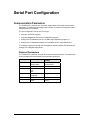
Protocol Parameters
The TeleBUS DF1 protocols are eight bit character-oriented protocols. The table below
shows possible and recommended communication parameters.
Parameter
Possible Settings
Baud Rate
see Baud Rate
section below
8 data bits
none
even
odd
1 stop bit
2 stop bits
disabled
see Duplex section
below
Data Bits
Parity
Stop bits
Flow control
Duplex
TeleBUS DF1 Protocol User and Reference Manual
Recommended
Setting
see Baud Rate
section below
8 data bits
none
1 stop bit
disabled
see Duplex section
below
5
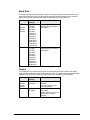
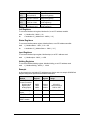
Baud Rate
The baud rate sets the communication speed. The possible settings are determined by the
type of serial data link used. The table below shows the possible settings for the controller.
Note that not all port types and baud rates are available on all controller ports.
Port Type
RS-232 or
RS-232
Dial-up
modem
RS-485
Possible
Settings
75 baud
110 baud
150 baud
300 baud
600 baud
1200 baud
2400 baud
4800 baud
9600 baud
19200 baud
38400 baud
57600 baud
115200 baud
75 baud
110 baud
150 baud
300 baud
600 baud
1200 baud
2400 baud
4800 baud
9600 baud
19200 baud
38400 baud
Recommended Setting
Use the highest rate
supported by all devices on
the network.
Use the highest rate
supported by all devices on
the network.
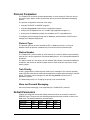
Duplex
The TeleBUS DF1 protocols communicate in one direction at a time. However the duplex
setting is determined by the type of serial data link used. The table below shows the possible
settings for the controller. Note that not all port types are available on all controllers.
Port Type
RS-232 or
RS-232
Dial-up
modem
RS-485
Possible
Settings
half duplex
full duplex
half duplex
full duplex
TeleBUS DF1 Protocol User and Reference Manual
Recommended Setting
Use full duplex wherever
possible.
Use half duplex for most
external modems.
Slave stations always use
half duplex.
Master stations can use full
duplex only on 4 wire
systems.
6
Protocol Parameters
The TeleBUS DF1 protocols operate independently on each serial port. Each port may set
the protocol type, station number, protocol task priority and store-and-forward messaging
options.
The protocol configuration can be set in four ways:
• using the TelePACE or ISaGRAF programs;
• using the set_protocol function from a C application program;
• writing to the I/O database from a C or ladder logic application program; or
• writing to the I/O database remotely from a Modbus or DF1 compatible device.
To configure protocol settings through the I/O database, add the module, CNFG Protocol
settings, to the Register Assignment.
Protocol Type
The protocol type may be set to emulate the DF1 or Modbus protocols, or it may be
disabled. When the protocol is disabled, the port functions as a normal serial port.
Station Number
The TeleBUS DF1 protocols allow up to 255 devices on a network. Station numbers identify
each device. A device responds to commands addressed to it, or to commands broadcast to
all stations.
The station number is in the range 0 to 254. Address 255 indicates a command broadcast to
all stations, and cannot be used as a station number. Each serial port may have a unique
station number.
Task Priority
A task is responsible for monitoring each serial port for messages. The real time operating
system (RTOS) schedules the tasks with the application program tasks according to the task
priority. The priority can be changed only with the set_protocol function from a C
application program.
The default task priority is 3. Changing the priority is not recommended.
Store and Forward Messaging
Store and forward messaging is not supported by the TeleBUS DF1 protocols.
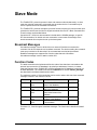
Default Parameters
All ports are configured at reset with default parameters when the controller is started in
SERVICE mode. The ports use user-defined parameters when the controller is reset in the
RUN mode. The default parameters are listed below.
Parameter
Baud rate
Parity
Data bits
com1
9600
none
8
com2
9600
none
8
TeleBUS DF1 Protocol User and Reference Manual
Com3
9600
None
8
com4
9600
none
8
7
Parameter
Stop bits
Duplex
Protocol
Station
Rx flow control
Tx flow control
Serial time out
Type
Minimum
Protected DF1
Address
Maximum
Protected DF1
Address
com1
1
full
Modbus
RTU
1
none
com2
1
full
Modbus
RTU
1
none
none
60 s
RS-232
0
Com3
1
Half
Modbus
RTU
1
Rx
disable
None
60 s
RS-232
0
com4
1
half
Modbus
RTU
1
Rx
disable
none
60 s
RS-232
0
none
60 s
RS-232
0
11534
11534
11534
11534
Notes
com3 is supported only when the SCADAPack Lower I/O module is installed. com4 is
supported only when the SCADAPack Upper I/O module is installed.
To optimize performance, minimize the length of messages on com3 and com4. Examples
of recommended uses for com3 and com4 are for local operator display terminals, and for
programming and diagnostics using the TelePACE program.
TeleBUS DF1 Protocol User and Reference Manual
8
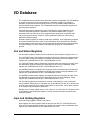
I/O Database
The TeleBUS protocols read and write information from the I/O database. The I/O database
is an area of memory that can be accessed by C programs, Ladder Logic programs,
ISaGRAF programs and communication protocols. The I/O database allows data to be
shared between these programs. The I/O database contains user-assigned registers and
general purpose registers.
User-assigned registers map directly to the I/O hardware or system parameter in the
controller. Assigned registers are initialized to the default hardware state or system
parameter when the controller is reset. Assigned output registers do not maintain their
values during power failures. However, output registers do retain their values during
application program loading.
General purpose registers are used by ladder logic, ISaGRAF and C application programs
to store processed information, and to receive information from remote devices. General
purpose registers retain their values during power failures and application program loading.
The values change only when written by an application program or a communication
protocol.
Coil and Status Registers
Coil and status registers contain one bit of information, that is whether a signal is off or on.
For TelePACE firmware coil registers are single bits which the protocols can read and write.
There are 4096 coil registers located in the digital output section of the I/O database. Coil
registers are contained within the DF1 16-bit addresses 0 to 255.
For TelePACE firmware status registers are single bits which the protocols can read. There
are 4096 status registers located in the digital input section of the I/O database. Status
registers are contained within the DF1 16-bit addresses 256 to 511.
For ISaGRAF firmware coil registers are single bits which the protocols can read and write.
There are 9999 coil registers located in the digital output section of the I/O database. Coil
registers are contained within the DF1 16-bit addresses 0 to 624.
For ISaGRAF firmware status registers are single bits which the protocols can read. There
are 9999 status registers located in the digital input section of the I/O database. Status
registers are contained within the DF1 16-bit addresses 625 to 1249.
Coil and status registers are accessed 16 at a time or individually (in some commands)
using a bitmask. Writing a one to a bit within the 16-bit address turns the bit on. Writing zero
to the bit turns the bit off. If the register is assigned to an I/O module, the bit status is written
to the module output hardware or parameter.
Reading a coil or status register returns 1 if the bit is on, or 0 if the bit is off. The stored value
is returned from general purpose registers. The I/O module point status is returned from
assigned registers.
Input and Holding Registers
Input and holding registers contain 16-bit values.
Input registers are 16-bit registers which the protocol can read. For TelePACE firmware,
there are 1024 input registers located in the analog input section of the I/O database. Input
registers are contained within the DF1 addresses 512 to 1535.
TeleBUS DF1 Protocol User and Reference Manual
9
For ISaGRAF firmware there are 9999 input registers located in the analog input section of
the I/O database. Input registers are contained within the DF1 addresses 1250 to 11247.
Holding registers are 16-bit registers that the protocol can read and write. For TelePACE
firmware there are 9999 holding registers located in the analog output section of the I/O
database. Holding registers are contained within the DF1 addresses 1536 to 11534.
For ISaGRAF firmware there are 9999 holding registers located in the analog output section
of the I/O database. Holding registers are contained within the DF1 addresses 11248 to
21247.
Writing any value to a general purpose register stores the value in the register. Writing a
value to an assigned register, writes the value to the assigned I/O module.
Reading a general purpose register returns the value stored in the register. Reading an
assigned register returns the value read from the I/O module.
Accessing the I/O Database Using TelePACE
Ladder logic programs access the I/O database through function blocks. All function blocks
can access the I/O database. The function blocks in ladder logic use only the Modbus
addressing scheme. Refer to the TelePACE Ladder Logic Reference and User Manual for
details.
C language programs access the I/O database with two functions. The dbase function reads
a value from the I/O database. The setdbase function writes a value to the I/O database.
These functions use either Modbus or DF1 physical addressing. Refer to the TelePACE C
Tools Reference and User Manual for full details on these functions.
Modbus Addressing
Modbus addressing is used in all ladder logic program functions. The controller’s Register
Assignment is also configured using Modbus addresses.
The C functions dbase and setdbase support Modbus addressing. When the specified port
is configured for one of the Modbus protocols, the function master_message uses Modbus
addressing.
Coil registers are single bit addresses ranging from 00001 to 04096.
Status registers are single bit addresses ranging from 10001 to 14096.
Input registers are 16-bit addresses in the range 30001 to 31024.
Holding registers are 16-bit addresses in the range 40001 to 49999.
DF1 Addressing
DF1 addressing is used by the MSTR ladder logic function when the specified port is
configured for one of the DF1 protocols. Modbus addressing must be used in all other ladder
logic program functions.
DF1 addressing is used by function master_message when the specified port is configured
for one of the DF1 protocols. The functions dbase, setdbase, setABConfiguration and
getABConfiguration also support DF1 addressing.
All DF1 addresses are absolute word addresses beginning with the first 16-bit register in the
I/O database at address 0 and ending at address 11534.
TeleBUS DF1 Protocol User and Reference Manual
10
Converting Modbus to DF1 Addresses
I/O database registers are assigned within the controller’s Register Assignment using
Modbus addressing. When polling the controller from an DF1 device it is necessary to know
the DF1 address corresponding to each assigned register.
In general, the cross-reference between Modbus and DF1 addressing is shown in the
following table. DF1 addresses in this table are described in the format word/bit where
word is the address of a 16-bit word and bit is the bit within that word. The bit address is
optional.
Address Range
Modbus 00001 to 04096
DF1
0/0 to 255/15
Modbus 10001 to 14096
DF1
256/0 to 511/15
Modbus 30001 to 31024
DF1
512 to 1535
Modbus 40001 to 49999
DF1
1536 to 11534
Description
Digital Output Database
(single bit registers)
Digital Input Database
(single bit registers)
Analog Input Database
(16-bit registers)
Analog Output Database
(16-bit registers)
Coil Registers
To convert a Modbus coil register, ModbusCoil, to an DF1 address word/bit:
word
= ( ModbusCoil - 00001 ) / 16
bit
= remainder of { ( ModbusCoil - 00001 ) / 16 }
Status Registers
To convert a Modbus status register, ModbusStatus, to an DF1 address word/bit:
word
= ( ModbusStatus - 10001 ) / 16 + 256
bit
= remainder of { ( ModbusStatus - 10001 ) / 16 }
Input Registers
To convert a Modbus input register, ModbusInput, to an DF1 address word:
word
= ( ModbusInput - 30001 ) + 512
Holding Registers
To convert a Modbus holding register, ModbusHolding, to an DF1 address word:
word
= ( ModbusHolding - 40001 ) + 1536
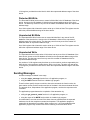
Example
In this example the equivalent DF1 addresses are shown next to a sample SCADAPack
Register Assignment specified with Modbus addresses.
Module
SCADAPack
Lower I/O module
digital outputs
digital inputs
analog inputs
Start
Register
End
Register
00001
10001
30001
00012
10016
30008
TeleBUS DF1 Protocol User and Reference Manual
DF1 Address
Range
0/0 to 0/11
256/0 to 256/15
512 to 519
11
Start
Register
10017
End
Register
10019
DIAG Force LED
10020
10020
257/3
SCADAPack
AOUT module
40001
40002
1536 to 1537
Module
DIN 5203/4 digital
inputs
DF1 Address
Range
257/0 to 257/2
Accessing the I/O Database Using ISaGRAF
ISaGRAF programs access the I/O database through function blocks. The function blocks in
ISaGRAF may use the Modbus addressing scheme when a Network Address is defined for
a variable. Refer to the IEC 61131 User Manual for details.
C language programs access the I/O database with two functions. The dbase function reads
a value from the I/O database. The setdbase function writes a value to the I/O database.
These functions use either Modbus or DF1 physical addressing. Refer to the IEC 61131
User Manual for full details on these functions.
Modbus Addressing
Modbus addressing can be used in ISaGRAF program functions. The controller’s Register
Assignment is also configured using Modbus addresses.
The C functions dbase and setdbase support Modbus addressing. When the specified port
is configured for one of the Modbus protocols, the function master_message uses Modbus
addressing.
Modbus addresses coil registers with a single bit address ranging from 00001 to 09999.
Status registers are also addressed with single bit addresses ranging from 10001 to 19999.
Input registers are addressed with 16-bit addresses in the range 30001 to 39999. And
holding registers are addressed with a 16-bit address in the range 40001 to 49999.
DF1 Addressing
DF1 addressing is used by the MSTR ladder logic function when the specified port is
configured for one of the DF1 protocols. Modbus addressing must be used in all other ladder
logic program functions.
DF1 addressing is used by function master_message when the specified port is configured
for one of the DF1 protocols. The functions dbase, setdbase, setABConfiguration and
getABConfiguration also support DF1 addressing.
All DF1 addresses are absolute word addresses beginning with the first 16-bit register in the
I/O database at address 0 and ending at address 21247.
Converting Modbus to DF1 Addresses
I/O database registers are assigned within the controller’s Register Assignment using
Modbus addressing. When polling the controller from an DF1 device it is necessary to know
the DF1 address corresponding to each assigned register.
In general, the cross-reference between Modbus and DF1 addressing is shown in the
following table. DF1 addresses in this table are described in the format word/bit where
word is the address of a 16-bit word and bit is the bit within that word. The bit address is
optional.
TeleBUS DF1 Protocol User and Reference Manual
12
Address Range
Modbus 00001 to 04096
DF1
0/0 to 624/15
Modbus 10001 to 14096
625/0 to 1249/15
DF1
Modbus 30001 to 31024
DF1
1250 to 11248
Modbus 40001 to 49999
DF1
11249 to 21247
Description
Digital Output Database
(single bit registers)
Digital Input Database
(single bit registers)
Analog Input Database
(16-bit registers)
Analog Output Database
(16-bit registers)
Coil Registers
To convert a Modbus coil register, ModbusCoil, to an DF1 address word/bit:
word
= ( ModbusCoil - 00001 ) / 16
bit
= remainder of { ( ModbusCoil - 00001 ) / 16 }
Status Registers
To convert a Modbus status register, ModbusStatus, to an DF1 address word/bit:
word
= ( ModbusStatus - 10001 ) / 16 + 625
bit
= remainder of { ( ModbusStatus - 10001 ) / 16 }
Input Registers
To convert a Modbus input register, ModbusInput, to an DF1 address word:
word
= ( ModbusInput - 30001 ) + 1250
Holding Registers
To convert a Modbus holding register, ModbusHolding, to an DF1 address word:
word
= ( ModbusHolding - 40001 ) + 11249
Example
In this example the equivalent DF1 addresses are shown next to a sample SCADAPack
Register Assignment specified with Modbus addresses.
Module
SCADAPack
Lower I/O module
digital outputs
digital inputs
analog inputs
Start
Register
End
Register
DF1 Address
Range
00001
10001
30001
00012
10016
30008
0/0 to 0/11
625/0 to 625/15
1250 to 1257
DIN 5203/4 digital
inputs
10017
10019
626/0 to 626/2
DIAG Force LED
10020
10020
626/3
SCADAPack
AOUT module
40001
40002
11249 to 111250
TeleBUS DF1 Protocol User and Reference Manual
13
Slave Mode
The TeleBUS DF1 protocols operate in slave and master modes simultaneously. In slave
mode the controller responds to commands sent by another device. Commands may be
sent to a specific device or broadcast to all devices.
The TeleBUS DF1 protocols emulate the protocol functions required for communication with
a host device which uses the Non-Privileged commands from the DF1 Basic Command Set.
These functions are described below.
Consult the DF1 I/O driver documentation included with the SCADA package, or specific
DF1 documentation, for details on these commands. In most cases a knowledge of the
actual commands is not required to set up the host system.
Broadcast Messages
A broadcast message is sent to all devices on a network. Each device executes the
command. No device responds to a broadcast command. The device sending the command
must query each device to determine if the command was received and processed.
Broadcast messages are supported for function codes that write information.
A broadcast message is sent to station number 255.
Function Codes
The table summarizes the implemented function codes. Note that slave commands at the
protocol layer access the I/O database in physical byte addresses. However, in master
mode the interface to the TeleBUS DF1 protocol accesses the I/O database in physical 16bit word addresses. The interface function block MSTR and C function master_message
are described in the Master Mode section below.
The maximum number of 16-bit words that can be read or written with one slave command
message is shown in the maximum column.
Function
00
01
02
05
08
Name
Description
Protected
Write
Unprotected
Read
Protected Bit
Write
Writes words of data to limited
areas of the database.
Reads words of data from any
area of the database.
Sets or resets individual bits
within limited areas of the
database.
Sets or resets individual bits in
any area of the database.
Writes words of data to any area
of the database.
Unprotected Bit
Write
Unprotected
Write
Maximum
121
122
30
30
121
Functions 0, 2, 5 and 8 support broadcast messages. The functions are described in detail
below.
TeleBUS DF1 Protocol User and Reference Manual
14
Protected Write
The Protected Write function writes 8 bit values into limited areas of the I/O database.
Access to the I/O database is limited to the protected address range.
Any number of bytes may be written up to the maximum number. The write may start at any
byte address, provided the entire block is within the protected address range.
The protected address range is set using the setABConfiguration function from a C
application program.
Unprotected Read
The Unprotected Read function reads 8 bit values from any area of the I/O database.
Access to the I/O database is limited to the unprotected address range.
Any number of bytes may be read up to the maximum number. The read may start at any
byte address, provided the entire block is within the unprotected address range.
Protected Bit Write
The Protected Bit Write function sets or resets individual bits within limited areas of the I/O
database. Access to the I/O database is limited to the protected address range.
Bits are accessed one byte at a time and may be written up to the maximum number of
bytes. The write may start at any byte address, provided the entire block is within the
protected address range.
Unprotected Bit Write
The Unprotected Bit Write function sets or resets individual bits in any area of the I/O
database. Access to the I/O database is limited to the unprotected address range.
Bits are accessed one byte at a time and may be written up to the maximum number of
bytes. The write may start at any byte address, provided the entire block is within the
unprotected address range.
Unprotected Write
The Unprotected Write function writes 8 bit values into any area of the I/O database. Access
to the I/O database is limited to the unprotected address range.
Any number of bytes may be written up to the maximum number. The write may start at any
byte address, provided the entire block is within the unprotected address range.
TeleBUS DF1 Protocol User and Reference Manual
15
Master Mode
The TeleBUS DF1 protocols may act as a communication master on any serial port. In
master mode, the controller sends commands to other devices on the network.
Simultaneous master messages may be active on all ports.
Function Codes
The table shows the implemented function codes. Note that slave commands at the protocol
layer access the I/O database in physical byte addresses. However, in master mode the
interface to the TeleBUS DF1 protocol accesses the I/O database in physical 16-bit word
registers. The interface function block MSTR and C function master_message are
described in the Sending Messages section below.
The maximum number of 16-bit registers that can be read or written with one message is
shown in the maximum column. The slave device may support fewer registers than shown;
consult the manual for the device for details.
Function
00
01
02
05
08
Name
Protected
Write
Unprotected
Read
Protected Bit
Write
Unprotected Bit
Write
Unprotected
Write
Description
Writes words of data to limited
areas of the database.
Reads words of data from any
area of the database.
Sets or resets individual bits
within limited areas of the
database.
Sets or resets individual bits in
any area of the database.
Writes words of data to any
area of the database.
Maximum
121
122
1
1
121
Protected Write
The Protected Write function writes 16-bit values into the I/O database of the slave device.
Access to the I/O database is limited to the protected address range of the slave device. The
data may come from any area of the master I/O database within its unprotected address
range.
Any number of 16-bit registers may be written up to the maximum number supported by the
slave device or the maximum number above, which ever is less. The write may start at any
16-bit register, provided the entire block is within the protected address range of the slave
device.
Unprotected Read
The Unprotected Read function reads 16-bit values from any area of the I/O database of the
slave device. Access to the I/O database is limited to the unprotected address range of the
slave device. Data can be written into any area of the master I/O database within its
unprotected address range.
Any number of 16-bit registers may be read up to the maximum number supported by the
slave device or the maximum number above, which ever is less. The read may start at any
TeleBUS DF1 Protocol User and Reference Manual
16
16-bit register, provided the entire block is within the unprotected address range of the slave
device.
Protected Bit Write
The Protected Bit Write function sets or resets individual bits in the I/O database of the slave
device. Access to the I/O database is limited to the protected address range of the slave
device. The data may come from any area of the master I/O database within the unprotected
address range.
One 16-bit register with a bitmask is used to write up to 16 bits of data. The register must be
within the protected address range of the slave device.
Unprotected Bit Write
The Unprotected Bit Write function sets or resets individual bits in any area of the I/O
database of the slave device. Access to the I/O database is limited to the unprotected
address range of the slave device. The data may come from any area of the master I/O
database within its unprotected address range.
One 16-bit register with a bitmask is used to write up to 16 bits of data. The register must be
within the unprotected address range of the slave device.
Unprotected Write
The Unprotected Write function writes 16-bit values into any area of the I/O database of the
slave device. Access to the I/O database is limited to the unprotected address range of the
slave device. The data may come from any area of the master I/O database within its
unprotected address range.
Any number of 16-bit registers may be written up to the maximum number supported by the
slave device or the maximum number above, which ever is less. The write may start at any
16-bit register, provided the entire block is within the unprotected address range of the slave
device.
Sending Messages
A master message is initiated in two ways:
• using the master_message function from a C application program; or
• using the MSTR function block from a ladder logic program.
These functions specify the port on which to issue the command, the function code, the
slave station number, and the location and size of the data in the slave and master devices.
The protocol driver, independent of the application program, receives the response to the
command.
The application program detects the completion of the transaction by:
• calling the get_protocol_status function in a C application program; or
• using the output of the MSTR function block in a ladder logic program.
A communication error has occurred if the slave does not respond within the expected
maximum time for the complete command and response. The application program is
responsible for detecting this condition. When errors occur, it is recommended that the
application program retry several times before indicating a communication failure.
TeleBUS DF1 Protocol User and Reference Manual
17
The completion time depends on the length of the message, the length of the response, the
number of transmitted bits per character, the transmission baud rate, and the maximum
message turn-around time. One to three seconds is usually sufficient. Radio systems may
require longer delays.
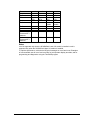
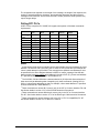
Polling DF1 PLCs
All DF1 PLCs, except the PLC-5/VME, will support some portion of the basic commands
implemented.
AB PLC
Unprotected
Read
Unprotected
Write
MicroLogix
4
1000
√
√
SLC500
√
√
√
√
√
√
√
√
√
√
√
√
√
√
√
√
√
√
√
√
SLC5/01
SLC5/02
SLC5/03
1,3
1,3
1,2,3
2,3
2,3
SLC5/04
1774-PLC
PLC-2
PLC-3
PLC-5
5
5
5
PLC-5/250
PLC-5/VME
Protected
Write
√
√
√
√
Protected
Bit Write
√
√
√
√
√
Unprotected
Bit Write
√
√
√
√
√
Notes
1
At the protocol level these commands convert and send the slave word address as a byte
address. The SLC500, 5/01 (and 5/02, prior to Series C FRN 3) treat this byte address as if
it were a word address in the SLC500. This means that the (desired word address)/2 must
be specified for the Slave Register Address in MSTR or master_message. Note that this
always results in an even starting word address in the slave SLC. (E.g. Slave word address
of 7 specified in MSTR accesses SLC word address 14.)
2
The SLC5/02, 5/03 and 5/04 have a status selection bit (S:2/8) which allows selection of
either word or byte addressing when interpreting only these commands. (Setting SLC bit
S:2/8 = 1 selects byte addressing so that, for example, a slave word address of 7 specified
in MSTR accesses SLC word address 7.)
3
These commands can access SLC memory only in the CIF or Common Interface File: N9.
See further details in section 12-15 of the SLC500 Instruction Set manual.
4
These commands can access MicroLogix memory only in the CIF or Common Interface
File: N7. See further details in section 12-15 of the MicroLogix 1000 Instruction Set manual.
5
These commands can access memory only in the CIF or “PLC-2 compatibility file”: N7.
See further details in section 16-7 of the PLC-5 manual.
TeleBUS DF1 Protocol User and Reference Manual
18