1
™
MD-300-V Vehicle Vibration Tool User's Guide
APMT-0350
March 2006
Important
Warnings and Cautions
ONE PERSON CANNOT PERFORM VIBRATION TESTING. A VEHICLE DRIVER
AND VIBRATION TEST TECHNICIAN ARE BOTH REQUIRED.
BEFORE INSTALLING OR REMOVING PRODUCTS TO BE TESTED, TURN OFF
THE IGNITION, PLACE THE TRANSMISSION IN NEUTRAL, SET THE PARKING
BRAKES, AND BLOCK THE WHEELS.
VEHICLE COMPONENTS MAY BE HOT. BE CAUTIOUS DURING INSTALLATION
AND REMOVAL OF SENSORS AND HARNESSES.
Always keep personal safety in mind when working on vehicles. Do not ignore
common sense.
Use appropriate safety equipment including:
• Safety glasses
• Safety shoes
• Gloves
• Proper transmission jack or lift with safety chains
• Guards and protective devices for presses, pullers, and drivers.
• Wheel chocks
To protect yourself and the vehicle always adhere to the following precautions:
•
•
•
•
•
•
•
Always refer to OEM manufacturer’s service procedures before
removing or replacing any equipment.
Keep yourself and equipment free from hot or moving parts.
Always disconnect the battery before replacing any electrical component.
Always use a properly ventilated area when the engine is running.
Always have the parking brakes applied, the transmission in neutral,
and wheels blocked when working on a vehicle.
Never leave a vehicle unattended with the engine running.
Never operate diagnostic equipment while driving the vehicle.
Table of Contents
Important......................................................... i
Warnings and Cautions.................................................................... i
License Agreement ............................................ 1
Introduction..................................................... 6
Eaton Support Hotline.................................................................... 6
Kit Contents ................................................................................... 7
Installing Software ............................................ 9
Getting Started ................................................ 11
Connecting the MD-300-V to the Vehicle ..................................... 11
Starting a New Test...................................................................... 18
MD-300-V Basic Program ................................... 20
Menu Bar ..................................................................................... 20
Setup Tab .................................................................................... 23
Test Tab ....................................................................................... 25
MD-300-V Advanced Program .............................. 27
Menu Bar .....................................................................................
Setup Tab.....................................................................................
Vehicle Information....................................................................
Transmission Ratios..................................................................
Speed Sensor Setup ..................................................................
Accelerometer Setup..................................................................
Test Tab .......................................................................................
Analysis Software Functions ........................................................
Menu Bar ...................................................................................
Linear Analysis Tab....................................................................
Torsional Analysis Tab ...............................................................
Order Tracking Tab ....................................................................
Spectral Maps Tab .....................................................................
28
30
30
32
33
34
36
38
39
41
45
48
51
Repair Strategies ............................................. 54
Troubleshooting the MD-300-V ............................. 63
Appendix ....................................................... 65
Removing the Diagnostic Software .............................................. 65
Slip Member Check ..................................................................... 66
Measure Yoke Runout.................................................................. 67
Checking and Correcting Tire Runout .......................................... 69
Change Control Log ...................................................................... 70
License Agreement
Software License Agreement
CLICK-WRAP LICENSE AGREEMENT FOR {Diagnostic Software}
IMPORTANT – READ CAREFULLY: This End-User License Agreement (“Agreement”) is a binding legal contract
between you (“End-User”) and between EATON CORPORATION, a Ohio corporation, and its successors and assigns (altogether referred to as “Licensor”) for the software product identified above, which includes computer
software and associated media, printed materials, a database of information, and “online” or electronic documentation, including without limitation any and all executable files, add-ons, stencils, templates, filters, tutorials, help
files, images, photographs, animations, video, audio, music, text, “applets” and other files and Information, that
accompany the (altogether, the “Software Product”).
BY CLICKING THE APPROPRIATE ICON BELOW, OR BY INSTALLING, COPYING, OR OTHERWISE USING THE
SOFTWARE PRODUCT, YOU AGREE TO BE BOUND BY THE TERMS OF THIS AGREEMENT. IF YOU DO NOT
AGREE TO THE TERMS OF THIS AGREEMENT, DO NOT INSTALL OR USE THE SOFTWARE PRODUCT.
You are entitled to receive a full refund of any payment made for the Software Product by so requesting and returning any media and materials in an unopened, unused condition within thirty (30) days of payment.
For purposes of this End-User License Agreement, "Software Product" refers to the computer software and associated media, printed materials, and "online" or electronic documentation, including without limitation any and
all executable files, add-ons, stencils, templates, filters, tutorials, help files, images, photographs, animations,
video, audio, music, text, “applets” and other files and Information, that accompany the Software Product; “Information” means manuals, training materials, or data, in any format whatsoever and not limited to digital, analog, components, or audio provided in connection with the Software Product; "Use" means storing, loading
(whether into temporary memory (i.e., RAM) or into permanent memory (e.g., hard disk, CD-ROM or other storage device), installing, executing or displaying the Software Product; the word "or" includes the word "and"; “Information Provider” means Licensor or related third-parties that provide Information used in connection with the
Software Product; "Claims or Losses" means any and all liabilities, obligations, losses, damages, penalties,
claims, actions, suits, costs, judgments, settlements, and expenses of whatever nature, whether incurred by or
issued against an indemnified party or a third party, including, without limitation, (i) indirect, special, punitive,
consequential or incidental loss or damage, (including, but not limited to, the ability to use a vehicle component,
loss of anticipated profits, loss by reason of shutdown in operation or increased expenses of operation, or other
indirect loss or damage) and (ii) administrative costs, investigatory costs, litigation costs, and auditors' and attorneys' and fees and disbursements (including in-house personnel); "Person" means any natural person, proprietorship, corporation, partnership, or other entity whatsoever; and, "You" or “End-User” means the End-User
listed above and any Person whose funds are used to pay the license fee or subscription fee (if applicable) or who
has otherwise acquired the Software Product or accepted delivery of the Information.
PROPRIETARY RIGHTS
As between Licensor and End-User, all right title and interest, including any and all copyrights or trade secrets,
in and to the Software Product, including, without limitation, the accompanying media and printed materials, and
any copies of the Software Product are owned by Licensor. You, as End-User, through payment of any license
fee or use of the Software Product do not acquire title, any ownership rights, or any proprietary or intellectual
property rights in and to the Software Product. Further, the Software Product is protected under various intellectual property laws, such as copyright law, patent law, trademark law, trade secret law, and international treaty
provisions. End-User acknowledges and agrees that the Software Product constitutes proprietary information
and trade secrets of Licensor, whether or not any portion thereof is or may be the subject of a valid copyright or
patent. End-User agrees to maintain the Software Product or any portion thereof in strict confidence and shall
not publish, communicate or disclose, or permit to be published communicated or disclosed, to third parties the
Software Product or any Information associated therewith without Licensor’s prior written consent. Further, you
as the End-User agree to take all reasonable steps to ensure that persons having access to the Software Product
are bound by the terms and conditions of this Agreement and refrain from any unauthorized reproduction or disclosure of the Software Product or any portion thereof.
Should you decide to transmit to Licensor, whether by electronic or non-electronic means, or by any media any
materials or other information (including, without limitation, ideas, concepts, techniques, data or pictures), in association with feedback, data, questions, comments, suggestions, inquiries, requests or otherwise, you agree
that such submissions are unrestricted and shall be deemed non-confidential at Licensor’s sole discretion. To
the extent that the submissions are in association with the use of the Software Product, the End-User shall maintain the confidentiality of the submission, as provided for herein. Moreover, you automatically grant Licensor and
its assigns a non-exclusive, royalty-free, worldwide, perpetual, irrevocable license, with the right to sublicense,
to use, copy, transmit, distribute, create derivative works of, display and perform the same.
1
License Agreement
LICENSE TERMS
Limited License. In consideration of the payment of each license fee, which is at least a percentage of the price
paid by you for the Software Product, and following your acceptance of this Agreement, without modification,
Licensor hereby grants End-User a non-exclusive, non-sublicensable, non-transferable, limited right to install
and execute one (1) registered copy of the current base version Software Product on a single computer, in machine-readable object code only. End-User shall not have the right to receive or use the source code for the Software Product. You may install the single registered copy on one hard disk or other storage device for one
computer, and you may access and use the Software Product at that location so long as only one copy of the
Software Product is in operation. You may also store or install a copy of the Software Product on a storage device, such as a network server, for the purpose of using the Software Product on your computers only over an
internal network. However, you must acquire and dedicate a license for each separate computer on which the
Software Product is used from the storage device. A single-use license for the Software Product may not be
shared or used concurrently on different computers.
If you are a business rather than an individual, you may authorize the personnel associated with your business
that agree to individually abide by the terms and conditions of this Agreement to use the Software Product, but
only one person at a time, on one computer at a time for each license that you have paid for. You agree to adopt
and enforce such internal policies, procedures, and monitoring mechanisms as are necessary to ensure that the
Software Product is used only in accordance with the terms and conditions of this Agreement. Further, you shall
not copy or modify the Software Product, except that you may copy the Software Product for the sole purpose
of backup as long as all copyright and other notices are reproduced and included on the backup copy.
End-User is solely responsible for the installation of the Software Product and is responsible for any conversion
of data required in connection with its use of the Software Product to make any such data compatible with the
Software Product. Licensor, at its sole discretion may provide you with support services related to the Software
Product (“Support Services”). Use of Support Services is governed by the policies and programs described by
Licensor in any associated user manual, in “online” documentation, and/or in other materials that it provides. Any
supplemental software code or data provided to you as part of the Support Services shall be considered part of
the Software Product and subject to the terms and conditions of this Agreement. With respect to technical information you provide to Licensor as part of the registration of your license to the Software Product or in connection
with the Support Services, Licensor reserves the right to use such information for its business purposes, including for product support and development.
Information. End-User is granted the right to use the Information under the terms stated herein. Licensor further
grants to End-User a non-exclusive, non-sublicensable, non-transferable right during the term of the Agreement
to use the Information solely in connection with the Software Product in accordance with the terms of the Agreement. End-User agrees and acknowledges that payment of the license fee(s) for the Software Product does not
entitle End-User to any information or data from any third party providers.
RESTRICTIONS ON USE
All rights not expressly granted are hereby reserved by Licensor.
The rights NOT GRANTED TO END-USER, include, but are not limited to the following, and End-User agrees to
be legally bound to the same:
•You may not sell, share, rent, lease or lend the Software Product or any output generated from the Software
Product. The output is for the sole and personal use of End-User.
•You may not alter, deface, decompile, translate or otherwise modify the Software Product or any output generated by the Software Product, including, but not limited to any copyright notices generated in association with
the output produced by the Software Product.
•No license is given to use any output from the Software Product for any other purpose. Nor is any license given
to create derivative works using any output from the Software Product.
•You may not reverse engineer, decompile, or disassemble the Software Product, except and only to the extent
that such activity is expressly permitted by applicable law notwithstanding this limitation.
•You may not break, disable or otherwise circumvent, or attempt to break, disable or circumvent, any encryption
that Licensor or its suppliers may include with the Software Product or with any Information associated therewith.
•You may not electronically transfer the Software Product through a local area network or other network system
or through any computer subscriber system or “bulletin board” system.
2
License Agreement
RESTRICTIONS ON TRANSFER AND DISCLOSURE
End-User shall not assign, sublicense, transfer, pledge, lease, rent, or share the license or any of the licensed
Software Product(s) without the prior written consent of Licensor, which may be withheld in Licensor’s sole discretion. Any attempt otherwise to assign, sublicense, transfer, pledge, lease, rent or share any of the rights, duties, or obligations hereunder without Licensor’s prior written consent is void and an immediate breach of the
terms and conditions of this Agreement.
End-User agrees that no output of the Software Product, whether aural, tactile, written, or otherwise, shall be
redisseminated, rebroadcast, or otherwise further disclosed to any other Person in any fashion whatsoever. EndUser may not sell, lease, furnish or otherwise permit or provide access to the Information to any other Person or
to any other office, or place. End-User will not use or permit anyone else to use the Information or any part thereof
for any illegal purpose. End-User shall take reasonable security precautions to prevent unauthorized Persons
from gaining access to the Information.
TERM AND TERMINATION
This Agreement is effective until terminated. The End-User may terminate this Agreement by returning the Software Product to Licensor. End-User may terminate this Agreement for convenience without cause upon ten (10)
days written notice to End-User. If Licensor terminates this Agreement for convenience during the first six (6)
months of the term, it shall refund the License fee to the End-User on a pro rata such that only one sixth-of the
End-User fee shall be refunded if termination takes place in the sixth month.
Notwithstanding anything to the contrary, this Agreement will terminate automatically and immediately (i) if EndUser breaches or fails to comply with any term or condition of this Agreement, without prejudice to any other
rights Licensor may have arising from End-User’s noncompliance, or (ii) if End-User becomes bankrupt or insolvent, but only to the extent permitted by law. In such event, no notice shall be required by Licensor to End-User
to effect such termination.
Upon termination of this Agreement for any reason, the End-User agrees to (i) immediately discontinue all use
of the Software Product; (ii) deliver to Licensor all diskettes, compact disks, or devices containing the Software
Product and all other physical copies of the Software Product; (iii) promptly destroy the Software Product together with all output generated by the Software Product along with all backup copies, modifications, printed or written materials, and merged portions; and (iv) certify in a writing to Licensor within one week after termination of
this Agreement that End-User has delivered to Licensor and destroyed the Software Product and all copies of the
Software Product in accordance with this Agreement.
INFRINGEMENT
Licensor shall have the right, in its sole discretion, to prosecute third parties for infringement of the rights associated with its Software Product. End-User agrees to fully cooperate with Licensor in the prosecution of any such
suit, at Licensor’s expense.
LIMITED WARRANTY
Licensor warrants only the media that contains the Software Product to be free from defects in materials and
workmanship under normal use for a period of thirty (30) days from the date of End-User’s receipt. End-User
shall assume responsibility for the installation, use of the Software Product, and results obtained from such use.
LICENSOR CANNOT AND DOES NOT WARRANT THAT THE SOFTWARE PRODUCT ON THE MEDIA OR THE INFORMATION WILL MEET END-USER’S REQUIREMENTS OR THAT THE USE OF EITHER THE MEDIA, THE SOFTWARE PRODUCT CONTAINED THEREIN OR THE INFORMATION (AS APPLICABLE) WILL BE UNINTERRUPTED
OR ERROR FREE. LICENSOR DOES NOT WARRANT THE SEQUENCE, ACCURACY, COMPLETENESS OR TIMELINESS OF INFORMATION, WHETHER USED OR USABLE BY THE SOFTWARE PRODUCT, AND WHETHER RECEIVED THROUGH A SUBSCRIPTION SERVICE OR FROM ANY PARTY, NOR DOES IT WARRANT ANY RESULTS
OR OUTCOMES PRODUCED BY THE SOFTWARE PRODUCT, THROUGH THE USE OF SUCH INFORMATION OR
THROUGH THE USE OF SUCH INFORMATION BY THE SOFTWARE PRODUCT.
The entire risk as to the quality and performance of the Software Product associated with the media, and the quality of the Information, is with End-User. Should the media prove defective for a reason other than one covered
by Licensor, End-User assumes the entire cost of all necessary servicing, repair, or correction. Some jurisdictions do not allow the exclusion of implied warranties, so the above exclusion may not apply to End-User. This
warranty gives End-User specific legal rights, and End-User may also have other rights that vary from jurisdiction
to jurisdiction.
3
License Agreement
REMEDIES
Licensor’s entire liability and End-User’s exclusive remedy shall be the replacement of any media not meeting
Licensor’s “Limited Warranty” above and that is returned to Licensor (along with evidence, sufficient in Licensor’s sole opinion, showing End-Users full and timely payment of all license fees). If Licensor is unable to deliver
a media containing the Software Product that is free of defects in materials or workmanship, End-User may terminate this Agreement by returning the media within thirty (30) days of the Effective Date for a full refund (if EndUser has paid any monies to Licensor). In no event will Licensor be liable for any damages, including but not
limited to, lost profits, lost savings, or other incidental or consequential damages arising out of the use or inability
to use the media or the Software Product associated with the media even if Licensor has been advised of the
possibility of such damages, or for any claim by any other party. Some jurisdictions do not allow the limitations
or exclusion of liability for incidental or consequential damages, so the above limitation or exclusion may not apply to End-User.
NO OTHER WARRANTIES/NO LIABILITY FOR DAMAGES
No Other Warranties.
SUBJECT TO THE FOREGOING STATEMENTS, THE ABOVE WARRANTIES ARE EXCLUSIVE, AND THE SOFTWARE PRODUCT AND THE INFORMATION (AS APPLICABLE) ARE PROVIDED “AS IS” WITHOUT ANY OTHER
WARRANTY OF ANY KIND, EITHER EXPRESS OR IMPLIED. TO THE MAXIMUM EXTENT PERMITTED BY APPLICABLE LAW, LICENSOR DISCLAIMS ALL OTHER WARRANTIES AND CONDITIONS, EITHER EXPRESS OR IMPLIED, INCLUDING, WITHOUT LIMITATION, IMPLIED WARRANTIES OF MERCHANTABILITY, FITNESS FOR A
PARTICULAR PURPOSE, TITLE, AND NON-INFRINGEMENT, THOSE ARISING OUT OF USE OF THE SOFTWARE
PRODUCT AND THOSE CONCERNING RECEIPT AND USE OF INFORMATION. NO ORAL OR WRITTEN INFORMATION OR ADVICE GIVEN BY LICENSOR, ITS AGENTS, DEALERS, DISTRIBUTORS OR EMPLOYEES SHALL INCREASE THE SCOPE OF THE ABOVE WARRANTIES OR CREATE ANY OTHER WARRANTIES.
No Liability for Damages.
REGARDLESS OF WHETHER ANY REMEDY SET FORTH HEREIN FAILS OF ITS ESSENTIAL PURPOSE, TO THE
MAXIMUM EXTENT PERMITTED BY APPLICABLE LAW, IN NO EVENT SHALL LICENSOR (OR ITS AGENTS, DIRECTORS, EMPLOYEES OR REPRESENTATIVES) BE LIABLE TO END-USER OR ANY OTHER PERSON FOR ANY
DAMAGES WHATSOEVER (INCLUDING, WITHOUT LIMITATION, CONSEQUENTIAL, INCIDENTAL, INDIRECT,
SPECIAL, ECONOMIC, PUNITIVE OR SIMILAR DAMAGES, OR DAMAGES FOR LOSS OF BUSINESS PROFITS,
LOSS OF GOODWILL, BUSINESS INTERRUPTION, COMPUTER FAILURE OR MALFUNCTION, TRADING LOSSES,
LOSS OF ANTICIPATED PROFITS, LOSS BY REASON OF SHUTDOWN IN OPERATION OR INCREASED EXPENSES OF OPERATION, COST OF COVER, LOSS OF BUSINESS INFORMATION OR ANY AND ALL OTHER COMMERCIAL OR PECUNIARY DAMAGES OR LOSSES) ARISING OUT OF THE USE OF OR INABILITY TO USE EITHER THE
SOFTWARE PRODUCT OR THE INFORMATION (AS APPLICABLE), HOWEVER CAUSED AND ON ANY LEGAL
THEORY OF LIABILITY (WHETHER IN TORT, CONTRACT OR OTHERWISE), EVEN IF LICENSOR HAS BEEN ADVISED OF THE POSSIBILITY OF SUCH DAMAGES, OR FOR ANY CLAIM BY ANY OTHER PARTY. LICENSOR
SHALL NOT BE LIABLE TO END-USER OR ANY OTHER PERSON FOR ANY UNAVAILABILITY, INTERRUPTION,
DELAY, INCOMPLETNESS, OR INACCURACY OF THE INFORMATION. END-USER ACKNOWLEDGES THAT THE
TERMS OF THIS AGREEMENT REFLECT THIS ALLOCATION OF RISK.
In any event, if any statute implies warranties or conditions not stated in this Agreement, Licensor’s entire liability
under any provision of this License Agreement shall be limited to the license fee actually paid by End-User to
license the Software Product or to receive the Information.
In addition to the foregoing, no action, regardless of form, arising out of this Agreement more than two (2) years
after any such cause of action has arisen.
INDEMNIFCATIONS
End-User agrees to defend, indemnify, and hold Licensor, and its officers, directors, agents, and employees,
harmless against any and all Claims or Losses (including reasonable attorney fees and costs) incurred through
claims of third parties against Licensor as a result of or relating to the acts (or omissions) of End-User (including
breach of this Agreement), its use of the Software Product and End-User’s receipt and use of any Information,
whether authorized or unauthorized under this Agreement, including, but not limited to, actions founded on product liability.
4
License Agreement
JURISDICTION AND DISPUTES
This Agreement shall be governed by the laws of the State of Ohio (without regard to conflict of law principles)
and the United States of America. All disputes hereunder shall be resolved in the applicable state or federal courts
in the State of Ohio. The parties consent to the jurisdiction of such courts, agree to accept service of process by
mail, and waive any jurisdictional or venue defenses otherwise available.
INTEGRATION
Notwithstanding any additional or different terms that may be set forth on Licensor’s web site, which may be
amended by Licensor from time to time in its sole discretion, or are set forth in a software license agreement
executed by Licensor and End-User, in which case such additional or different terms shall control, the terms and
conditions of this Agreement shall be deemed to control and constitute the entire understanding of the parties.
Both parties have carefully read and understand the terms and conditions of this Agreement and, as such, the
terms and conditions contained herein shall not be construed against a party hereto because such party has drafted, or primarily drafted, such language or provision.
NO WAIVER
The failure of either party to enforce any rights granted hereunder or to take action against the other party in the
event of any breach hereunder shall not be deemed a waiver by that party as to subsequent enforcement of rights
or subsequent actions in the event of future breaches.
NOTICES
All notices and other communications to Licensor that are required or permitted under this Agreement will be in
writing and will be deemed given when delivered personally or by registered or certified mail, return receipt requested, addressed as follows (or any other address that is subsequently specified by Licensor):
If to Licensor: EATON CORPORATION
SURVIVAL CLAUSES
All provisions of this Agreement relating to Licensor’s proprietary rights, disclaimers, and limits of liability or duty, confidentiality, non-disclosure, End-User’s actions upon termination, payment of fees by End-User, or indemnification by End-User shall survive the termination of this Agreement for any reason.
ENFORCEMENT; ATTORNEY FEES
If any legal action is necessary to enforce this Agreement, the prevailing party shall be entitled to reasonable attorney fees, costs, and expenses in addition to any other relief to which it may be entitled.
TITLES AND HEADINGS.
Titles and headings to articles, sections, or paragraphs in this Agreement are inserted for convenience of reference only and are not intended to effect the interpretation or construction of this Agreement.
INVALID, ILLEGAL OR UNENFORCEABLE PROVISIONS
In the event that any one or more of the provisions of this Agreement shall for any reason be held by any tribunal
of competent jurisdiction to be invalid, illegal or unenforceable, the remaining provisions of this Agreement shall
be unimpaired, and each invalid, illegal or unenforceable provision shall be treated by the tribunal as modified to
the least extent necessary to rectify its invalidity, illegality or unenforceability and shall be enforces as so modified.
SUCCESSORS AND ASSIGNS
This Agreement will be binding upon and inure to the benefit of parties’ successors and permitted assigns. Licensor may assign its rights and obligations under this Agreement without End-User’s consent. End-User may
not assign its rights or obligations under this Agreement. The Agreement is personal to the End-User. Any attempt by End-User to assign its rights and obligations shall be null and void.
SUBSEQUENT CONFLICTS
Notwithstanding any additional or different terms that may be set forth in the present Agreement, to the extent
that there is any ambiguity or conflict between the present agreement and any Web Site End-User Agreement on
Licensor’s web site, which may be amended by Licensor from time to time in its sole discretion, the Web Site
End-User Agreement shall be deemed to supersede the present Agreement. For the most recent copy of the Web
Site End-User Agreement, please go to the URL http://sr.eaton.com, or contact the Licensor as provided for
above.
5
Introduction
Introduction
The Eaton MD-300-V vibration tool is designed to provide the ability to isolate
fundamental vehicle vibrations for quicker diagnostics and repair. By using vehicle speed, this tool pinpoints vibration problems that, in the past, have been
difficult to diagnose.
There are two versions of the MD-300-V tool software; Basic and Advanced.
The Basic version provides the set-up, testing, data collection, and reporting of
information in an easy-to-use format. The Advanced version provides an engineering level view of the gathered data.
The separate MD-300-V Analysis software comes with the MD-300-V Advanced program. The Analysis software allows for in-depth studying using vibration analysis tools on both live and saved data.
If additional support is needed, Vehicle Vibration Reports can be collected and
sent to a Vibration Analyst to review for a fee.
Eaton Support Hotline
For further assistance, call the Roadranger Call Center at 1-800-826-HELP
(4357). Please have the following information ready:
• A brief explanation of the problem you are having.
• Include the exact wording of any error or warning message you have
received.
• Give the sequence of steps you took before the error occurred.
• Describe any changes made to your computer recently, and if the
software was running correctly in the past.
6
Introduction
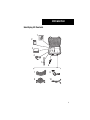
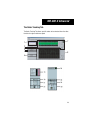
Kit Contents
The MD-300-V Vehicle Vibration Analysis Kit includes:
#
Name
Qty
Purpose
1
Software CD
1
Contains all necessary PC software
2
PC Card
1
Inserted into the PC to collect the vehicle speeds and vibration data
3
Signal Conditioner
1
Conditions the raw vehicle signal for
the PC software
4
Accelerometer
(Vibration Sensor)
1
Used to provide vibration input
through the seat bracket
5
Tap (3/4” -16NC)
1
To clean threads for threaded speed
sensor in flywheel housing or transmission speedometer rear bearing
cover
6
Speedometer Sensor
(Push in)
1
Used for transmission output speed,
where necessary
7
Speedometer Pick-up
Adapter (SPA) Cables
6
Used to connect the speedometer
pick-up to the speed cables
8
Gray Speed Cables
2
Connects the speed inputs to the
signal conditioner
9
Data Cable
1
Connects the signal conditioner to
the data card
10 Flywheel Sensor
1
Used for transmission input speed
7
Introduction
Identifying Kit Contents
1
2
3
Power
Tach Ch 1
Driveline V ibration Analyzer
Tach Ch 2
Accel 1
Accel 2
Accel 3
4
5
6
7
9
8
10
8
Installing Software
Diagnostic Software Installation
PC Requirements
In order to successfully run the diagnostic tool, you will need the following
components:
A PC should meet the following minimum configuration:
• IBM® PC-compatible computer - Pentium III or equivalent
(1 GHz or better)
• 256 Mb of RAM minimum (512 recommended)
• Screen resolution
• Basic - 1024 x 768 (XGA)
• Advanced - 1280 x 800 (SXGA)
• CD-ROM drive
• 400 Mb of free space on hard drive
• Microsoft Windows 2000, NT, or XP
9
Installing Software
How to Install the MD-300-V Software
Use the following procedure to install the software onto your PC.
1. Close any applications currently running.
2. Insert the software CD in the CD-ROM drive.
3. The install program should start automatically. If it does not:
a. From the task bar, press the “Start” button and select RUN.
b. In the dialogue box, type: d:\setup.exe and click on OK.
Note: “d” is the letter of your CD-ROM drive.
4.
5.
Read through the Welcome screen and click on NEXT to continue.
Follow the screen prompts to complete the installation process.
Note: The default path is the recommended installation location.
6.
Re-start the PC if prompted to do so.
Note: Due to wide variances from computer configurations, the setup program
might differ from the procedure just described.
10
Getting Started
Connecting the MD-300-V to the Vehicle
Your Vehicle Connections
Although every attempt has been made to provide connections to most medium- and heavy-duty vehicles, not all connections can be covered. In most cases, you will be able to tee into the existing speed sensor connections on the
vehicle. If not, you may need to place an additional sensor on the vehicle. Additional flywheel and transmission output speed sensors are provided (see “Kit
Contents” on page 7). Both engine speed and transmission output speed are
required for the test.
CAUTION
Do not modify vehicle harnesses.
Connecting to the Vehicle
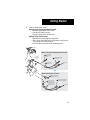
1.
2.
3.
4.
11
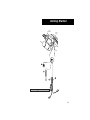
Remove plug from flywheel sensor hole.
Run the tap into the hole to make sure threads are clear.
Install sensor:
a. Screw sensor in until it touches the flywheel.
b. Back sensor out 1/2 to 3/4 turn.
Lock sensor in place by tightening jam nut against flywheel housing.
Getting Started
Output
Shaft Sensor
Flywheel
Sensor
Bottom View
1
2
4
3
CAUTION
Tie cables away from all hot and moving parts
12
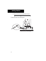
Getting Started
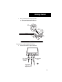
5.
Feed gray cable down from cab and connect to sensor.
CAUTION
Tie cables away from all hot and moving parts.
5
Gray Speed
Cable from
Cab
CAUTION
Tie cables away from all hot and moving parts
13
Getting Started
6.
Install the output shaft sensor:
Option A: Using Existing Speedometer Sensor
1. Remove wiring harness from sensor.
2. Connect SPA cable to sensor.
3. Connect wiring harness to SPA cable.
Option B: Using Push-in Sensor
1. Remove jam nut and plug from sensor hole.
2. Push sensor into sensor hole until tight and re-install jam nut.
Then connect SPA cable to sensor.
3. Tie SPA cables away from all hot and moving parts.
Bottom View
Option A: Using Existing Speedometer Sensor
1
Existing
Speedometer
Sensor
Remove wiring
harness from
sensor
3
2
Connect wiring harness
to SPA cable
From Cab
Connect SPA
cable to sensor
– OR –
Sensor
Hole
Option B: Using Push-In Sensor
1
2
Remove jam nut and
plug from sensor hole
Push sensor into
sensor hole until
tight and re-install
jam nut. Connect
SPA cable to sensor.
3
Tie SPA cables away from
all hot and moving parts
From Cab
14
Getting Started
7.
Feed gray speed cable down from the cab and connect to the SPA
cable.
CAUTION
Tie cables away from all hot and moving parts.
7
SPA
Cable
Gray
Speed
Cable
CAUTION
Tie cables away from all hot and moving parts
15
Getting Started
8.
Place accelerometer on driver seat mount:
a. Clean mounting area with cloth / rag.
b. Point arrow toward front of vehicle.
8
Fr
Ve ont
hic of
le
TM
Driver
Seat
WARNING
Route cable so as not to interfere with driving
WARNING
Route cable so as not to interfere with driving.
9. Connect three cables to signal conditioner.
Power
Tach Ch 1
Gray Speed
Cable from
Flywheel
Driveline Vibration Analyzer
Tach Ch 2
Accel 1
Accel 2
z3
Accelerometer
Cable
9
Gray Speed
Cable from
Output Shaft
16
Getting Started
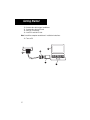
10.
11.
12.
13.
Connect data cable to signal conditioner.
Connect data cable to PC card.
Verify PC is turned off.
Install PC card into PCI slot.
Note: Consult the computer manufacturer’s installation instructions.
14. Turn on PC.
12
DATA CABLE
10
11
13
14
17
Getting Started
Starting a New Test
Once the software has been installed and the cables have been connected correctly, the gathering data phase can begin.
1. Select the MD-300-V icon on the desktop or go to Start, Programs,
and locate the MD-300-V software in your programs list.
2. Select “New Test” from the Startup Dialog box.
3.
Select the location and file folder name for the test data to be saved
under.
18
Getting Started
4.
Select the driveline configuration that matches the vehicle using the
up and down arrow keys.
5.
Select the desired startup mode. Note: This option will not be displayed if only the Basic level is available.
6.
After verifying the accelerometer is placed correctly, click the “Check
Accel” button and follow the on-screen steps to verify the accelerometer is functioning properly. See page 63 to troubleshoot any card errors.
7.
Fill in the data on the Setup Tab as required on page 23 for the Basic
level or on page 30 for the Advanced level.
Note: When using the software for the first time, or after installing a
new accelerometer, you must enter the Accelerometer Setup data.
8. Take the vehicle for a test drive with an assistant. Drive the vehicle at
the condition where the vibration exists at a steady speed and gear
while gathering test data. During the test drive, review and record the
data displayed on the Test Tab as indicated on page 25 for the Basic
level or on page 36 for the Advanced level.
9. Use the “Analysis Software Functions” on page 38 to further identify
the vibration, if necessary.
10. Follow the “Repair Strategies” on page 54 to assist in vibration corrections.
19
MD-300-V Basic
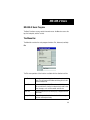
MD-300-V Basic Program
The Basic Functions screens contain three main areas: the Menu bar across the
top, the Setup tab, and the Test tab.
The Menu Bar
The Menu Bar contains the main program functions: File, Advanced, and Help.
File
The File menu provides all the functions available with the vibration test files.
New Test
Creates a new test and requires the user to enter a test
name. This will create a file folder containing all test information and data files.
Open Test
Opens an existing test file. This can be useful if the previous test vehicle was similar in setup and only needs a few
minor changes, such as VIN number and tire size.
Save Test
Saves the current test file including any changes that have
been made.
Change Driveline Allows changes to the driveline selection if the wrong one
has been selected previously.
20
MD-300-V Basic
Page Setup
Changes the report printing options including headers,
margins, and printer destinations.
Print Window
Prints the current screen to the desired printer.
Exit
Exits the current test.
Advanced
The Advanced menu provides program customization to best fit user needs.
Add User
Transmission
Allows for entering a new transmission configuration or
modifying an existing configuration listed in the software.
This includes the manufacturer, model, forward speeds,
reverse speeds, input torque, output torque, forward gear
ratios, and reverse gear ratios. Selecting “Cancel” at the
bottom of the screen will discard any changes made.
Preferences
Changes the default directory that files are saved in and
the length of the data file saved during testing. Type in the
directory name or use the “Browse” button to change the
default directory. Use the up and down arrows to modify
the standard 30 second time frame (not recommended).
21
MD-300-V Basic
Accel Setup
Displays the main accelerometer sensor calibration data
and allows for input of the mounting location description
and accelerometer serial number. Adjustments to the
sensitivity and offset can be made using the up and down
arrows.
Note: This information is required when using the program for the first time or when an accelerometer is replaced.
Help
The Help menu provides useful information on the product functions and the
version level.
22
MD-300-V Basic
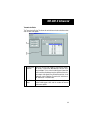
The Setup Tab
The Setup Tab records vehicle information and checks the accelerometer is
functioning properly. Not all information is required, but it is suggested to provide the best correlation with shop records. The number of flywheel teeth (see
7 above) and all information in red are required before starting the test.
1
Vehicle Info
2
Tire Diameters Enter the steer axle and drive axle tire diameters in inches (measured from the ground to the top of the tire).
3
Engine
23
Enter information about the vehicle including: unit
number, fleet name, truck manufacturer, truck model,
VIN number, vehicle mileage, wheel base, RO number,
and the name of the individual conducting the test.
Select the number of engine cylinders. This is critical to
identifying engine related vibrations.
MD-300-V Basic
4
Transmission
Select the transmission model by choosing the Production Status, Transmission Manufacturer, and the Transmission model. This is critical to identify gear
information and the relationship between engine speed
and transmission output shaft speed. If the desired
transmission is not displayed, use the “Add User Transmission” selection under “Advanced” in the Menu Bar.
5
Axle
Enter the axle ratio as stated on the axle tag. This is critical to isolating axle vibrations.
6
Driveline
Configuration
Displays the driveline configuration selected when the
test started. If the proper configuration is not displayed,
use the “Change Driveline” selection under “File” in the
Menu Bar.
7
Engine
Flywheel
Enter the number of flywheel teeth OR use the “Find
Teeth” button (recommended) and follow the onscreen steps to get an accurate tooth count.
8
Transmission
Output
Enter the number of teeth on the tone wheel at the
transmission output shaft. (For Eaton Fuller transmissions the number is usually 16.)
9
Accelerometer The accelerometer check must be performed daily to
ensure the accelerometer has not been damaged. Follow the on-screen steps to verify each side of the sensor is functioning properly. Once completed, the
program will advise if the accelerometer is damaged.
10 Vibration
Complaint
Enter any vibration complaint notes. These notes will
appear on all reports and files recorded during testing.
24
MD-300-V Basic
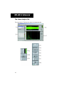
The Test Tab
1
6
2
7
3
4
5
The Test Tab is used once the Setup Tab screen is complete. It is an active window during the data collection process.
1 Analyzer
Start and Stop
Buttons
Used to start and stop the vibration analysis test function. Vehicle must be moving to start test.
Note: If the vehicle comes to a stop, the test will need to
be restarted.
2 Saved File List
Any data that has been saved during the current test will
be displayed in the list.
3 Current Gear
Position
Shows the current gear position while the vehicle is in
motion during a test.
4 Collect a
Vibration
Allows the data to be collected while the vehicle is in motion during a test. (NOTE: The vehicle must be held at a
steady speed and gear while gathering test data.) To
change the amount of time data is collect for, use the
“Preferences” selection under “Advanced” in the Menu
Bar. (Not recommended)
WARNING: Use caution when driving at slow speeds
and obey all traffic laws.
25
MD-300-V Basic
5 Pause Display
Freezes the current screen information in order to review
it on screen or use the “Print Window” selection under
“File” in the Menu Bar.
6 Vehicle Sensor Provides a view of the vibration sensor inputs to comInformation
pare with vehicle gauges and verify they are functioning
properly.
7 Vibration
Analysis
Table
Indicates the source(s) of the vibration. Red indicates a
problem vibration has been detected. Yellow indicates a
vibration has been detected, but below levels that need
correction. Green indicates the tool has not found a
problem vibration.
Test Tab Measurements
Below are charts of how the MD-300-V measures the linear and torsional vibrations.
Linear Vibrations
Measurement
Level
< 70 mg
Green
> 70 mg
Red
Torsional Vibrations
0 - 300
rad/s2
300 - 1000
rad/s2
> 1000
rad/s2
< 0.30
Green
Green
Green
0.3 - 1
0
Green
Yellow
Red
> 10
Green
Red
Red
26
MD-300-V Advanced
MD-300-V Advanced Program
Note: Advanced Functions are only found in the engineering version of the vibration analysis software.
The Advanced functions provide a user, skilled in vibration analysis, the ability
to review actual sensor information by utilizing vibration analysis graphs. The
program also allows for live FFT (Fast Fourier Transform) analysis of linear and
torsional vibration information.
While viewing torsional information, the user can review vibration orders using
acceleration or displacement on the Y-axis. The ability to review vibration frequency and order plotted against acceleration is also available. In addition,
there are more speed sensor and vibration input options.
The Advanced Functions screens contain six main areas: the Menu bar across
the top, the four sections of the Setup tab: Vehicle Information, Transmission
Ratios, Speed Sensor Setup, Accelerometer Setup, and the Test tab.
27
MD-300-V Advanced
The Menu Bar
The Menu Bar contains the main program functions (identical to that of the Basic Functions Menu Bar): File, Advanced, and Help.
File
The File menu provides all the functions available with the vibration test files.
New Test
Creates a new test and requires the user to enter a test
name. This will create a file folder containing all test information and data files.
Open Test
Opens an existing test file. This can be useful if the previous test vehicle was similar in setup and only needs a few
minor changes, such as VIN number and tire size.
Save Test
Saves the current test file including any changes that have
been made.
Change Driveline Allows changes to the driveline selection if the wrong one
has been selected previously.
Page Setup
Changes the report printing options including headers,
margins, and printer destinations.
Print Window
Prints the current screen to the desired printer.
Exit
Exits the current test.
28
MD-300-V Advanced
Advanced
The Advanced menu provides program customization to best fit user needs.
Add User
Transmission
Allows for entering a new transmission configuration or
modifying an existing configuration listed in the software.
This includes the manufacturer, model, forward speeds,
reverse speeds, input torque, output torque, forward gear
ratios, and reverse gear ratios. Selecting “Cancel” at the
bottom of the screen will discard any changes made.
Preferences
Type a default directory for files to be saved in or use the
“Browse” button. Use the up and down arrows to modify
the number of pre-trigger and post-trigger seconds. Pretigger seconds sets the number of seconds data is gathered before the “Collect a Vibration” button is depressed
on the Test Tab. The post-trigger seconds sets the number of seconds data is gathered after data collection is
stopped.
Spectrum Setup
Changes the technical setup of the program. These settings should not be changed without advice from a vibration analyst.
Help
The Help menu provides useful information on the product functions and the
version level.
29
MD-300-V Advanced
The Setup Tab
The Setup Tab is broken into four sections: Vehicle Information, Transmission
Ratios, Speed Sensor Setup, and Accelerometer Setup.
Vehicle Information
The Vehicle Information Tab records vehicle information. Not all information is
required, but it is suggested to provide the best correlation with shop records.
All information in red is required before starting the test.
1 Vehicle Info
Enter information about the vehicle including: Unit number, fleet name, fleet account number, truck manufacturer, truck model, VIN number, vehicle mileage, vehicle
build date, RO number, transmission serial number,
wheel base, and the name of the individual conducting
the test.
2 Vibration
Complaint
Enter any vibration complaint notes. These notes will appear on all reports and files recorded during testing.
30
MD-300-V Advanced
3 Driveline
Configuration
Displays the driveline configuration selected when the
test started. If the proper configuration is not displayed,
use the “Change Driveline” selection under “File” in the
Menu Bar.
4 Engine
Select the engine make, model, and number of cylinders.
This is critical to identifying engine related vibrations.
5 Axle
Enter the axle ratio as stated on the axle tag. This is critical to isolating axle vibrations.
6 Tire Diameters Enter the steer axle and drive axle tire diameters in inches
(measured from the ground to the top of the tire).
31
MD-300-V Advanced
Transmission Ratios
The Transmission Ratios Tab allows for vehicle transmission selection and review of ratios and speeds.
1 Transmission Select the transmission model by choosing the ProducSelection
tion Status, Transmission Manufacturer, and the Transmission Model. This is critical to identify gear information
and the relationship between engine speed and transmission output shaft speed.If the desired transmission is not
displayed, use the “Add User Transmission” selection under “Advanced” in the Menu Bar.
2 Gear Ratio
Setup
Displays all information specific to the transmission selected including gear ratios and the number of forward
and reverse speeds.
32
MD-300-V Advanced
Speed Sensor Setup
The Speed Sensor Setup Tab provides options for placing the speed sensors at
different locations along the driveline. It also displays the number of gear teeth
identified by the speed sensor pickups. The user can also identify where test
files will be saved.
Select different speed sensor locations using the drop down
1 Speed
box and corresponding pictures to best isolate the vehicle viSensor
Locations bration. The selections include:
- Trans Flywheel RPM (ch1) & Trans Output RPM (ch2)
- Trans Input RPM (ch1) & Trans Output RPM (ch2)
- Trans PTO RPM (ch1) & Trans Output RPM (ch2)
2 Number
of Teeth
Enter the number of teeth for both sensor locations OR use
the “Find Teeth” button and follow the on-screen steps to get
an accurate tooth count. The number of flywheel teeth must
be accurate for the system to make vibration calculations.
Note: The channel information is color coded to match the
speed sensor location arrows in the pictures.
3 Data File
Setup
Enter the desired location and name for saving test files.
33
MD-300-V Advanced
Accelerometer Setup
The Accelerometer Setup Tab displays the sensor calibration data. It is important for vibration measurement accuracy and should be input when the program is installed or the sensor is changed.
1
Main
Displays the main accelerometer sensor calibration
Accelerometer data and allows for input of the mounting location description and accelerometer serial number. AdjustInformation
ments to the sensitivity and offset can be made using
the up and down arrows.
Note: This information is required when using the
program for the first time or when an accelerometer
is replaced.
2
Check
The accelerometer check must be performed daily to
Accelerometer ensure the accelerometer has not been damaged. Follow the on-screen steps to verify each side of the sensor is functioning properly. Once completed, the
program will advise if the accelerometer is damaged.
34
MD-300-V Advanced
3
35
Optional
Used to provide two additional single channel accelerAccelerometer ometer inputs. Press the “Off” button to activate the acChannels
celerometer and then input sensor information. As with
the main accelerometer, the accelerometer check must
be performed daily to ensure the accelerometer has not
been damaged. Follow the on-screen steps to verify
each side of the sensor is functioning properly. Once
completed, the program will advise if the accelerometer
is damaged.
MD-300-V Advanced
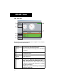
The Test Tab
The Test Tab is used once the Setup Tab screen is complete. It is an active window during the data collection process.
1 Analyzer
Start and Stop
Buttons
Used to start and stop the vibration analysis test function. Note: If the vehicle comes to a stop, the test will
need to be restarted.
2 Saved File List
Any data that has been saved during the current test will
be displayed in the list.
3 Display Type
Used to switch between the Basic Function Test screen
and the Advanced Function Test screen.
4 Current Gear
Position
Shows the current gear position while the vehicle is in
motion during a test.
36
MD-300-V Advanced
5 Collect a
Vibration
Allows the data to be collected while the vehicle is in motion during a test. (NOTE: The vehicle must be held at a
steady speed and gear while gathering test data.) To
change the amount of time data is collect for, use the
“Preferences” selection under “Advanced” in the Menu
Bar.
WARNING: Use caution when driving at slow speeds
and obey all traffic laws.
6 Pause Display
Freezes the current screen information in order to review
it on screen or use the “Print Window” selection under
“File” in the Menu Bar.
7 Vehicle Sensor Provides the option to activate or deactivate the graphInformation
ing of sensor information. Press the squares to the right
of each input to toggle them on (green) or off (red).
8 Vibration
Display
Channel
Provides a list of the vibration sensor inputs and select
which will be displayed in the bottom graph for analysis.
Depending upon the sensor input selected, either the Xor Y-axis information options will be displayed. X-axis
information can show either frequency (in Hz) or order
of the vibration in relation to accelerometer signals (vertical, lateral, fore-aft). When speeds are used, Y-axis information can show either angular acceleration (rad/
sec2) or angular displacement (degrees) of torsional activity in the driveline.
9 Cursor
Information
Several color-coded cursors are listed to assist in finding vibration relationships by level and the vibration order or frequency (in Hz).
37
MD-300-V Advanced
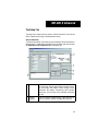
Analysis Software Functions
The separate MD-300-V Analysis software comes with the MD-300-V Advanced program. The Analysis software allows for in-depth studying using vibration analysis tools on both live and saved data.
The Analysis functions provide a user, skilled in vibration analysis, the ability
to import vibration analysis information saved from the MD-300-V (Basic or
Advanced) program. The data files can also be sent to a Vibration Analysis
Technician if additional assistance is needed.
The Analysis Functions screens contain five main areas: the Menu bar across
the top, the Linear Analysis tab, the Torsional Analysis tab, the Order Tracking
tab, and the Spectral Maps tab.
38
MD-300-V Advanced
The Menu Bar
The Menu Bar contains the main program functions: File, Edit, and Help.
File
The File menu provides all the functions available with the vibration test files.
Select Files
Opens data that will be used for analysis including the location of the Current Path files on the computer, a list of
the Current Files, a list of the Selected Files, and File Control Keys that allow files to be selected or deselected.
Page Setup
Changes the report printing options including headers,
margins, and selecting a printer destination.
Print
Creates a print report which can be exported to a printer
or as an image file.
Exit
Closes the program.
39
MD-300-V Advanced
Edit
The Advanced menu provides basic editing functions.
Spectrum Setup
Changes the technical setup of the program. These settings should not be changed without advice from a vibration analyst.
Help
The Help menu provides useful information on the product functions and the
version level.
40
MD-300-V Advanced
The Linear Analysis Tab
The Linear Analysis Tab allows the review of accelerometer data.
41
MD-300-V Advanced
1
File Selection
Choose the file to be analyzed.
2
File Info and
Vibration Info
The File Info tab displays the vehicle information collected during the vibration test including comments.
The Vibration Info tab displays color-coded cursors
corresponding to the graph to determine the proper
source of the vibration peaks.
3
File Data and
Graph Control
Displays the data as it was collected from the vehicle
during testing.
3a Input View
Controls
Press the squares to the right of each input to turn
them on (green) or off (red).
3b Graph Pallet
Controls
Provides zooming and panning of the graph for a better
view. Selecting the magnifying glass provides several
zoom in options. Selecting the hand allows for easy
movement of the data in the viewing window.
3c Plot Scaling
Controls
Modifies the scaling and view of the graph. The X or Y
axis information can be locked or unlocked. Once unlocked, the number format can be changed to decimal,
scientific, or engineering. Decimal precision can also
be modified from 0-6 decimal places. The mapping
mode alters the graph to linear or logarithmic scales.
The viewing of the graph scale and labels can be toggled on or off. Grid colors can also be changed.
4
Choose the way the vibration data is displayed.
Analysis and
Graph Control
4a Frame
Number
The MD-300-V collects data in frame segments. As the
data is analyzed it can be displayed one frame at a time
(a frame is indicated by the blue lines on the graph) using the up and down arrows.
42
MD-300-V Advanced
4b Spectrum
Setup
The Analog FFT Settings allow alterations to the block
size (512 to 16,384 data points), averaging (select between 3 and 6 blocks to analyze), and percent overlap
(25% - 90% overlap of block data). The window type
control selects the type of vibration analysis to be used.
The X and Y axis scaling allows the X-axis to be viewed
by order or frequency and the Y-axis to be viewed by
voltage peak, RMS, peak squared, RMS squared, or g’s
peak. G’s peak is the default setting and should not be
changed without advice from a vibration analyst.
Note: Torsional FFT Settings do not apply to accelerometer information.
4c Auto Play
Displays the data from beginning to end as it was gathered to watch specific spectrum values change through
time.
4d Gear Position
Shows the transmission gear position for the data currently displayed on screen.
4e Graph Palette
Controls
Provides zooming and panning of the graph for a better
view. Selecting the magnifying glass provides several
zoom in options. Selecting the hand allows for easy
movement of the data in the viewing window.
4f
Modifies the scaling and view of the graph. The X and
Y axis information can be locked or unlocked. Once unlocked, the number format can be changed to decimal,
scientific, or engineering. Decimal precision can also
be modified from 0-6 decimal places. The mapping
mode alters the graph to linear or logarithmic scales.
The viewing of the graph scale and labels can be toggled on or off. Grid colors can also be changed.
43
Plot Scaling
Controls
MD-300-V Advanced
4g Cursor
Controls
The left button on the cursor bar allows the cursor pad
at the bottom of the screen to be toggled on or off. The
center button changes the cursor color, style, and line
width. The right button locks the cursor grid line, snaps
to data points, or allows for a free floating cursor.
The harmonics button can display 1, 2, or 3 harmonics
simultaneously.
The cursor control diamond allows the cursor to move
one data point at a time.
44
MD-300-V Advanced
The Torsional Analysis Tab
The Torsional Analysis Tab allows the review of angular acceleration (rad/s2)
and angular displacement (degrees) for each tach channel.
45
MD-300-V Advanced
1
File Selection
Choose the file to be analyzed.
2
File Info and
Vibration Info
The File Info tab displays the vehicle information collected during the vibration test including comments.
The Vibration Info tab indicates the plot cursors displayed, Y-axis scaling viewed by displacement or acceleration, and color-coded flywheel and output cursors
corresponding to the graph to determine the proper
source of the vibration peaks.
3
File Data and
Graph Control
Displays the data as it was collected from the vehicle
during testing.
3a Input View
Controls
Press the squares to the right of each input to turn
them on (green) or off (red).
3b Graph Pallet
Controls
Provides zooming and panning of the graph for a better
view. Selecting the magnifying glass provides several
zoom in options. Selecting the hand allows for easy
movement of the data in the viewing window.
3c Plot Scaling
Controls
Modifies the scaling and view of the graph. The X or Y
axis information can be locked or unlocked. Once unlocked, the number format can be changed to decimal,
scientific, or engineering. Decimal precision can also
be modified from 0-6 decimal places. The mapping
mode alters the graph to linear or logarithmic scales.
The viewing of the graph scale and labels can be toggled on or off. Grid colors can also be changed.
4
Choose the way the vibration data is displayed.
Analysis and
Graph Control
4a Frame
Number
The MD-300-V collects data in frame segments. As the
data is analyzed it can be displayed one frame at a time
(a frame is indicated by the blue lines on the graph) using the up and down arrows.
46
MD-300-V Advanced
4b Spectrum
Setup
The Torsional FFT Settings allow alterations to the
block size (1/12 to 1/96 of order resolution) and percent overlap (none, 25%, 50%, 75%, or 90% overlap of
block data). The window type control selects the type of
vibration analysis to be used. The X and Y axis scaling
allows the X-axis to be viewed by order or frequency
and the Y-axis to be viewed by displacement or acceleration. Note: Analog FFT Settings do not apply to linear vibration information.
4c Auto Play
Displays the data from beginning to end as it was gathered to watch specific spectrum values change through
time.
4d Gear Position
Shows the transmission gear position for the data currently displayed on screen.
4e Graph Palette
Controls
Provides zooming and panning of the graph for a better
view. Selecting the magnifying glass provides several
zoom in options. Selecting the hand allows for easy
movement of the data in the viewing window.
4f
Modifies the scaling and view of the graph. The X and
Y axis information can be locked or unlocked. Once unlocked, the number format can be changed to decimal,
scientific, or engineering. Decimal precision can also
be modified from 0-6 decimal places. The mapping
mode alters the graph to linear or logarithmic scales.
The viewing of the graph scale and labels can be toggled on or off. Grid colors can also be changed.
Plot Scaling
Controls
4g Cursor
Controls
47
The left button on the cursor bar allows the cursor pad
at the bottom of the screen to be toggled on or off. The
center button changes the cursor color, style, and line
width. The right button locks the cursor grid line, snaps
to data points, or allows for a free floating cursor.
The harmonics button can display 1, 2, or 3 harmonics
simultaneously.
The cursor control diamond allows the cursor to move
one data point at a time.
MD-300-V Advanced
The Order Tracking Tab
The Order Tracking Tab allows specific orders to be extracted from the vibration data for a given reference speed.
1
7
2
3
4
5
8
6
48
MD-300-V Advanced
1
File Selection
Choose the file to be analyzed.
2
Channel to
Track
Select the desired data channel to be reviewed from the
pull down list.
3
Reference
Speed
Select the flywheel or output speed source.
4
Plot Type
Select if the level will be plotted against RPM or speed.
5
Vibration to
Track
Select the desired vibration source to be reviewed from
the pull down list.
6
Extract Order
and
Copy Data
Once the “Channel to Track” and “Vibration to Track”
options are selected, Extract Order will create a revised
vibration graph. Copy Data duplicates the current information which can then be imported into a spreadsheet
for further analysis.
7
File Data and
Graph Control
Displays the data as it was collected from the vehicle
during testing.
7a Input View
Controls
Press the squares to the right of each input to turn
them on (green) or off (red).
7b Graph Pallet
Controls
Provides zooming and panning of the graph for a better
view. Selecting the magnifying glass provides several
zoom in options. Selecting the hand allows for easy
movement of the data in the viewing window.
7c Plot Scaling
Controls
Modifies the scaling and view of the graph. The X or Y
axis information can be locked or unlocked. Once unlocked, the number format can be changed to decimal,
scientific, or engineering. Decimal precision can also
be modified from 0-6 decimal places. The mapping
mode alters the graph to linear or logarithmic scales.
The viewing of the graph scale and labels can be toggled on or off. Grid colors can also be changed.
49
MD-300-V Advanced
7d Cursor
Controls
The left button on the cursor bar allows the cursor pad
at the bottom of the screen to be toggled on or off. The
center button changes the cursor color, style, and line
width.
The cursor control diamond allows the cursor to move
one data point at a time.
8
Allow for movement and cursor control configuration.
Order Graph
Control
8a Graph
Identifier
Shows which order is currently displayed on the graph.
8b Graph Palette
Controls
Provides zooming and panning of the graph for a better
view. Selecting the magnifying glass provides several
zoom in options. Selecting the hand allows for easy
movement of the data in the viewing window.
8c Plot Scaling
Controls
Modifies the scaling and view of the graph. The X and
Y axis information can be locked or unlocked. Once unlocked, the number format can be changed to decimal,
scientific, or engineering. Decimal precision can also
be modified from 0-6 decimal places. The mapping
mode alters the graph to linear or logarithmic scales.
The viewing of the graph scale and labels can be toggled on or off. Grid colors can also be changed.
8d Cursor
Controls
Within the order graph, there are two cursors that can
be placed on any of the information points for review.
The left button on the cursor bar allows the cursor pad
at the bottom of the screen to be toggled on or off. The
center button changes the cursor color, style, and line
width. The right button locks the cursor grid line, snaps
to data points, or allows for a free floating cursor.
The cursor control diamond allows the cursor to move
one data point at a time.
50
MD-300-V Advanced
The Spectral Maps Tab
The Spectral Maps Tab allows the review of the entire data file at once to get an
overall picture of vibration trends.
51
MD-300-V Advanced
1
File Selection
Choose the file to be analyzed.
2
Process Bar
Indicates the progress of the extraction when the “Extract Order” button (5) is pressed.
3
Channel to
Track
Select the desired data to be reviewed from the pull
down list.
4
Vibration to
Track
Select the desired vibration to be reviewed from the pull
down lists. These selections include:
- Plot Type: Choose order or frequency vs. time or RPM.
- Graph Type: Choose Waterfall or Spectral Map.
If Waterfall is selected you can then choose vertical or
orthogonal display.
5
Extract Order
Once the “Channel to Track” and “Vibration to Track”
options are selected, this will create a revised vibration
graph.
6
File Data and Displays the data as it was collected from the vehicle
Graph Control during testing.
6a Input View
Controls
Press the squares to the right of each input to turn them
on (green) or off (red).
6b Graph Pallet
Controls
Provides zooming and panning of the graph for a better
view. Selecting the magnifying glass provides several
zoom in options. Selecting the hand allows for easy
movement of the data in the viewing window.
6c Plot Scaling
Controls
Modifies the scaling and view of the graph. The X or Y
axis information can be locked or unlocked. Once unlocked, the number format can be changed to decimal,
scientific, or engineering. Decimal precision can also be
modified from 0-6 decimal places. The mapping mode
alters the graph to linear or logarithmic scales. The
viewing of the graph scale and labels can be toggled on
or off. Grid colors can also be changed.
52
MD-300-V Advanced
6d Cursor
Controls
The left button on the cursor bar allows the cursor pad
at the bottom of the screen to be toggled on or off. The
center button changes the cursor color, style, and line
width.
The cursor control diamond allows the cursor to move
one data point at a time.
7
Once the “Channel to Track” and “Vibration to Track”
options are selected and the Extract Order button is
pressed this displays a revised vibration graph.
53
Order Graph
Repair Strategies
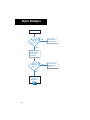
Repair Strategies
Now that vibration data has been gathered and analyzed, it is time to implement
driveline changes to eliminate the vibrations. Areas identified as needing correction are colored red on screen. Use the following flowcharts to correct the
vibration by matching the identified source with the flowchart name.
NOTE: If more than one area is colored red, each one must be corrected.
54
Repair Strategies
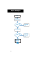
Engine
Check Engine
Operation and Tuning
Problem
Found?
Yes
Correct Per OEM
Procedures and
Re-test
Yes
Replace Engine
Mounts per OEM
procedures and
Re-test
No
Check Engine Mounts
Problem
Found?
No
Contact Roadranger
Support Team
1-800-826-4357
55
Repair Strategies
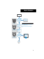
Propshaft
Does
vehicle
carrier bearing have
a solid rubber
isolator?
Yes
No
CAUTION
Solid
Remove all axle
shafts on driver side
of vehicle and lock in
power divider
Semi-Slotted
Install Slotted or
Semi-Slotted Rubber
Isolator and Re-test
If vehicle is equipped with locking or limited slip differential
ALL axle shafts must be removed.
Do not run for more than 90 seconds, as axle damage can
occur.
Run vehicle with
transmission in gear
at speed where
problem occurs
Can Vibration
Be Duplicated
in Garage?
No
Contact Roadranger
Support Team
1-800-826-4357
Full Slotted
Yes
Propshaft
Cont'd
56
Repair Strategies
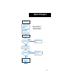
Propshaft
Cont'd
Starting with rear-most
vehicle (propshaft)
driveshaft, remove one
section at a time and
run vehicle with
transmission in gear
at speed where
problem occurs to
isolate suspect shaft.
Problem
Found?
NOTE: If suspect shaft has
slip spline, see "Appendix
- Slip Member Check" for
procedure to check wear.
Yes
Check suspect driveshaft
balance and runout or replace
driveshaft then re-test
No
Check yokes using
protractor and dial
indicator to measure
yoke run-out
Excesssive
Run-out
Found?
No
Contact Roadranger
Support Team
1-800-826-4357
57
NOTE: For instructions to
measure yoke runout, see
"Appendix - Measure Yoke
Runout" .
Yes
Replace yoke and
re-test
Repair Strategies
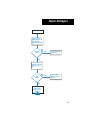
Driveline Angles
Check Driveline
Angularity Using the
Eaton Driveline
Angle Analyzer (DAA)
Problem
Found?
Yes
Reset Components
and Re-test
Yes
Install Correct
Components per
OEM Spec and
Re-test
No
Inspect if Suspension
Bushings and Torque
Rods are loose or
worn
Problem
Found?
No
Contact Roadranger
Support Team
1-800-826-4357
58
Repair Strategies
Axle Gear Set
Remove Inter-axle
Shaft, Lock Power
Divider, and Re-run
Test Using MD-300-V
Problem
Found?
Yes
Verify the Inter-axle Shaft
has the Proper Length and
Phasing and Re-test
No
Correct Per OEM
Procedures and
Re-test
No
Check Drive Head
Assembly Setup Per
Manufacturer Specs
Are
measurements
within specs??
Yes
Contact Roadranger
Support Team
1-800-826-4357
59
Repair Strategies
Wheel End
If Complaint Occurs
Only When Pulling a
Trailer, Check
Trailer Tires for
Runout
NOTE: For instructions to
measure tire runout, see
"Appendix - Checking and
Correcting Tire Runout."
Check Vehicle
Wheel and Tire
Assembly for Runout
Check Balance
Are
measurements
within specs?
No
Replace Suspect
Wheel or Tire and
Re-test
No
Replace Suspect
Brake Drum or Rotor
and Re-test
Yes
Check Brake Drums
or Rotors for Runout
Are
measurements
within specs?
Yes
Contact Roadranger
Support Team
1-800-826-4357
60
Repair Strategies
Clutch (torsional)
Does Vehicle
Have Soft
Rate Clutch?
No
Install Soft Rate
Clutch and Re-test
Yes
Replace Suspect
Components and
Re-test
Yes
Remove Clutch and
Check for: Broken
springs, disc, or
other damage
Suspect
Components
Found?
No
Contact OEM
or Clutch
Manufacturer
61
Repair Strategies
U-Joint (torsional)
Check Driveline
Angularity Using the
Eaton Driveline
Angle Analyzer (DAA)
Problem
Found?
Yes
Reset Components
and Re-test
Yes
Contact U-joint
Manufacturer and
Re-test
No
Inspect if Suspension
Bushings and Torque
Rods are loose or
worn
Problem
Found?
No
Contact Roadranger
Support Team
1-800-826-4357
62
Troubleshooting
Troubleshooting the MD-300-V
Speed input is not displayed
If the Tach Ch 1 or Tach Ch 2 power lights are not illuminated green, verify the
following:
•
•
•
•
Cable has been correctly inserted into the signal conditioner.
Speed sensor has been inserted the proper depth from the gear.
All cable connections are fully inserted.
Cable is fully functional by swapping it with the other speed cable.
Transmission gear is not displayed
If gear information is not recognized, verify the following:
•
•
Return to the Setup screen and verify speed sensor information has
been correctly identified. See page 23 for the Basic level or on
page 33 for the Advanced level.
Verify the correct transmission has been selected.
Software displays a card error
If the software does not recognize the card is connected to the PC, verify the
following:
• Card has been correctly inserted into the properly into the PC.
• Card has been inserted into the correct slot in the PC.
• Cable has been correctly connected to the card.
• Cable has been correctly connected to the signal conditioner
• Card is fully functional by conducting the following test:
1. Start National Instruments Measurement and Automation software.
2. Selected “Devices and Interfaces”.
3. Select “Traditional NI-DAQ Devices”.
4. Select the “DAQCard 6024E”.
5. Click on “Properties” at the top of the screen.
6. Click on “Test Resources” and verify the tests passed.
7. If the tests did not pass, try another card slot.
63
Troubleshooting
No vibration input
If vibration input is not recognized, the accelerometer has not been connected
properly. Verify the following:
•
•
•
•
•
Cable has been correctly inserted into the proper port of the signal
conditioner.
Cable has been correctly inserted into the signal conditioner.
All cable connections are fully inserted.
Accelerometer is fully functional. See the Accelerometer Check on
page 23 for the Basic level or on page 34 for the Advanced level.
Cable is fully functional.
64
Appendix
Removing the Diagnostic Software
In the event that the diagnostic tool program has to be deleted, use the Add/
Remove Program utility in the Control Panel program group. This will safely remove the software program from your computer.
Instructions
To uninstall the software:
1. Click on the ‘START’ button on the Task Bar. From the menu, select
‘SETTINGS’ and then ‘CONTROL PANEL’.
2. Click on the ADD/REMOVE PROGRAMS icon. The following screen
will be displayed:
3. Highlight diagnostic tool from the text box, then click on the
CHANGE/REMOVE button.
4. The following screen should be displayed:
• Click on NEXT to remove the diagnostic software from your computer.
Note: If a dialog box appears asking you to remove shared files, click the ‘NO
TO ALL’ button.
5.
6.
65
When the uninstall is complete, click on the ‘OK’ button.
Finally, click on the ‘OK’ button on the ‘ADD/REMOVE Programs Property’ dialog box.
Appendix
Slip Member Check
Figure A
Figure B
To check a Spicer Life slip member for broken back (movement perpendicular
to shaft axis) the shaft should remain installed with the vehicle resting on its
wheels.
1. Arrange dial indicator with magnetic base one-quarter inch (1/4”)
from the driveshaft’s tube weld. Dial indicator should be firmly
mounted on the tube so that no movement of the dial indicator base
is allowed.
2. Extended dial indicator arm from the base, across the slip member
boot, allowing the dial indicator to contact the yoke shaft tube onequarter inch (1/4”) off the opposite side of the boot from where the
magnetic base is mounted. Dial indicator’s arm should be running
parallel to the driveshaft. (See Figure A)
3. Apply effort perpendicular to shaft axis making note of total indicator
travel. (See Figure B) Allowable indicator travel is .000 - .012 inches.
66
Appendix
Measure Yoke Runout
To check a Spicer Life end yoke for excessive runout (greater than .005”) the
transmission output yoke and drive axle input and output yokes must be measured.
Note: If measuring SPL or Half-Round Yoke styles, go to Step 2.
1.
Remove the universal joint end caps so the measurement can be
made on the machined yoke surface. (See below)
Machined
Area
2.
Rotate the yoke being measured to the 12 o’clock position. Place the
protractor on the yoke and rotate the yoke so the protractor reads “0”.
SPL and Half-Round Yokes
67
Full-Round Yokes
Appendix
3.
Place the dial indicator base on the transmission case or the axle
housing being measured.
Machined
Area
SPL and Half-Round Yokes
4.
SPL and Half-Round Yokes
6.
Full-Round Yokes
Move the dial indicator probe so that it contacts the machined surface. Adjust the dial indicator so the dial reads “0”.
Machined
Area
5.
Machined
Area
Machined
Area
Full-Round Yokes
Pull the dial indicator probe upward, rotate the yoke 1/2 turn or 180
degrees and release the probe. Be sure only the probe moves upward
and not the dial indicator so the reference measurement made in Step
4 is not compromised. Record measurement.
Compare the measurement made in Step 4, which was “0”, to the second measurement taken in Step 5. If the difference is greater than
.005” the yoke must be replaced.
68
Appendix
Checking and Correcting Tire Runout
Use a tire runout gauge, or dial indicator, to check lateral and radial runout. Lateral runout should be checked on a smooth surface along the tire's mid-sidewall. Radial runout should be checked on a smooth rib in the center of the
tread, if possible.
Record the minimum and maximum radial and lateral runout measurements.
The maximum tire runout shouldnot exceed .125". If necesssary contact the
appropriate Tire Manufacturer for runout limits.
69
Appendix
Change Control Log
Last Revised Date
Description of Clarifications and Updates
23 Mar 2006
Updated Wheel End section
Added “Checking and Correcting Tire Runout”
Updated warning and caution symbols
70
Eaton MD™ Tools are provided to Eaton
Corporation by AutoXray Inc.
1-800-826-HELP (4357)
www.roadrangerstore.com
Eaton Corporation
Roadranger Parts Marketing
PO Box 4013
Kalamazoo, MI 49003
U.S.A
www .eatonmdtools.com
APMT-0350
Printed in USA
©2004 Eaton Corporation. EATON CORPORATION hereby grants its customers, vendors, or
distributors permission to freely copy, reproduce and/or distribute this document in printed
format. THIS INFORMATION IS NOT INTENDED FOR SALE OR RESALE, AND THIS NOTICE MUST
REMAIN ON ALL COPIES.