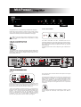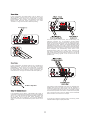
1
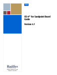
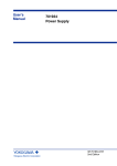
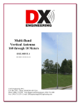
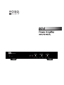
MI4
The lightning flash with
arrowhead symbol, within an
equilateral triangle, is intended
to alert the user to the presence
of un-insulated dangerous
voltage within the products
enclosure that may be of
sufficient magnitude to
constitute a risk of electric
shock to persons.
1.
2.
3.
4.
5.
6.
7.
8.
9.
10.
11.
12.
13.
Warning: To reduce the risk of
electric shock, do not remove
cover (or back). No user
serviceable parts inside. Refer
servicing to qualified service
personnel.
The exclamation point within
the equilateral triangle is
intended to alert the user to the
presence of important
operating and maintenance
(servicing) instructions in the
literature accompanying the
appliance.
Read these instructions.
Keep these instructions.
Read all warnings.
Follow all instructions.
Do not use this appliance near water.
Clean only with dry cloth.
Do not block any ventilation openings. Install in accordance with the manufacturer's
instructions.
Do not install near heat sources such as radiators, heat registers, stoves, or other
appliance (including amplifiers) that produce heat.
Do not defeat the safety purpose of the polarized or grounding type plug. A polarized plug
has two blades with one wider than the other. A grounding type plug has two blades and a
third grounding prong. If the provided plug does not fit into your outlet, consult an
electrician for replacement of the obsolete outlet.
Protect the power cord from being walked on or pinched particularly at the plugs,
convenience receptacles, and at the point where they exit from the appliance.
Only use attachments or accessories specified by the manufacturer.
Unplug the appliance during lightning storms or when unused for long periods of time.
Refer all servicing to qualified personnel. Servicing is required when the appliance has
been damaged in anyway, such as power supply cord or plug is damaged, liquid has been
spilled or objects have fallen into the appliance, the appliance has been exposed to rain
or moisture, does not operate normally, or has been dropped.
This appliance shall not be exposed to dripping or splashing water and no object filled with
liquids such as vases shall be placed on appliance.
MI4 Power
Congratulations on your purchasing of OSD Power Amplifier.
OUTPUT ADJUSTMENT
Please take a few moments to read the entire manual, and be
sure to retain this document for future reference. Please read
and observe all safety instructions detailed on each page.
Note: If any part of this product is damaged or missing,
please call OSD AUDIO Return Department at (562)
697-2600
The RIGHT VOLUME and LEFT VOLUME knobs are for
individual adjustment of left channel and right channel output.
The corresponding L/MAX and R/MAX LED show the output
level status. when the output is adjusted to reach clip, they will
illuminate RED.
The BASS GAIN knob is used for adjust the gain of Bass for the
output.
The POWER push button will manually switch the MI4 Power
amplifier on or off. The blue LED beside the button indicate its
power status. Whenever the amplifier’s power switch is on, the
LED will illuminate blue.
T3.15AL/250V
INPUTS
The Line 2 has “OUT” RCA connectors to loop the Line 2 signal
to other devices.
There is a total of 2 pairs of RCA input on the rear panel of the
MI4 Power Amplifier. These RCA inputs are labeled as “Line 1"
and “ Line 2". They are also designed with an “R” and “L” as
Right Channel and Left Channel inputs respectively.
“Line 2" Input should be used as the primary or normal input for
various line level sources that may be available locally to the
amplifier. “Line 1" Input is a priority switching input that can be
used for a second input, such as, the output of a second
source, and will take over as primary input whenever the signal
is present. If the “Line 1" Input signal is absent after 12
seconds, the input will revert to the “Line 2" Input signal.
The MI4 Power Amplifier also provides a pair of speaker level
input labeled as “Speaker In” for those applications where
either of the sources has only speaker level output signal
available. The Speaker In signal will be mixed with Line 1 or
Line 2 input signal controlled by the switch labeled “Line 1"
and “Line 2" as option on the right side of “Line 1" Input RCA
connectors.
This screwdriver adjustment knob labeled as “LEVEL” can be
used to adjust the sensitivity of MI4 inputs from “MIN” to
“MAX”.
OUTPUT
To the right of the Speaker Out connectors is a switch labeled
:Mode” with “Stereo” and “Bridged” as options. It is used to
switch the output mode of MI4.
If you will be connecting a pair of speakers to the amplifier,
place the switch in the “Stereo” Position. If you will be using a
pair channels to power a single mono speaker, place the
switch in the “Bridged” position.
NOTE: This amplifier is capable of use with standard US
voltage (115V) as well as European voltage (230V). The
amplifier will be preset for the voltage of the country it is
sold in. Use with other voltages requires some changes
to be made to the amplifier. Should you wish to use the
amplifier in a country other than the one for which it was
purchased, please contact OSD AUDIO at (562) 6972600.
Limited Warranty
OSD AUDIO: warrants its amplifier products against defects in
materials and workmanship for a limited period of time. For a
period of two years from date of original purchase, we will
repair or replace the product, at our option, without charge for
parts and labor.
This limited warranty applies only to purchases from
authorized OSD AUDIO retailers. This limited warranty is
extended only to the original purchaser and is valid only to
customers in USA.
The MI4 Power Amplifier has 2 channels outputs. Each
channel has a pair of multi-way binding post connectors.
These are red and black screw posts on the rear panel of the
amplifier. Terminals are provided for “L” and “R” output. If you
will use the amplifier with a stereo mode(not a bridged mode),
connect the speaker’s positive(Red) terminal to the amplifier’s
positive(Red) terminal using the appropriate gauge speaker
wire, and connect the speaker’s negative(Black) terminal to
the amplifier’s negative(Black) terminal(immediately beside
the positive terminal) using the appropriate gauge speaker
wire.
If you would like to use the amplifier with “Bridged” mode,
place the “Mode” Switch in the “Bridged” Position to be a single
channel mono amplifier, the two channels will be internally
connected in series. You will use both Red terminals to connect
to the speaker, the “L” channel’s Red terminal will be positive
terminal and the “R” channel’s Red terminal will be negative
terminal under “Bridged” mode.
Note: This amplifier will supply 130W in “Bridged”
mode. Please verify that your speakers are capable of
handling such power to avoid possible damage!
Customers are required to provide a copy of the original sales
invoice from an authorized OSD AUDIO dealer when making a
claim against this limited warranty. This limited warranty only
covers failures due to defects in materials or workmanship that
occur during normal use. It does not cover failures resulting
from accident, misuse, abuse, neglect, mishandling,
misapplication, alteration, faulty installation, modification,
service by anyone other than OSD AUDIO or damage that is
attributable to acts of god. It does not cover costs or
transportation to OSD AUDIO or damage in transit. The
customer should return their defective product, freight prepaid
and insured, to OSD AUDIO, only after receiving a Returned
Merchandise Authorization (RMA) number.
This warranty will become void if the serial number
identification has been wholly or partially removed, altered or
erased. Repair of replacement under the terms of this warranty
does not extend the terms of this warranty. Should a product
prove to be defective in workmanship or material, the
customer’s sole remedies will be repair or replacement as
provided under the terms of this warranty. Under no
circumstances shall OSD AUDIO be liable for loss or damage,
direct, consequential or incidental, arising out of the use of or
inability to use the product.
Note: The minimum impedance for the total load
connected to a pair of channels in the “Bridged”
mode is 8-ohm.
MI4 Power Amplifier Specifications
Power Bandwidth: 20Hz - 20kHZ
50W per Channel into 8 ohms loads with less than 0.05% THD+N
65W per Channel into 4 ohms loads with less than 0.1% THD+N
130W Bridged Mono into 8 ohms with less than 0.1% THD+N
Crosstalk: >60dB@1KHz, referred to rated power at 8 ohms
Frequency Response: (25Hz to 50kHz) +0dB, -1.0dB
Signal to Noise ratio: >98dB
RCA Line Input Sensitivity: 220mV (Max)
Speaker Input Sensitivity: 2.3V (Max)
AC Power Consumption: 360W (All Channels Driven)
Dimensions: 19"w x 7.87"d x 2.85"h,
“1.5U Option Rack Space Style”
Net Weight: 5.65 kg
Gross Weight: 6.25 kg
AC Mains Fuse:
115V~60Hz T3.15AL, 250V
230V~50Hz T3.15AL, 250V
Whenever you are using speakers outdoors, you should
be aware that sound does not travel like it would be in
your home. Without the reflective surfaces of walls and
ceilings, sound at outdoors will dissipate quickly.
Therefore, in an outdoor situation the MI4 Power
Amplifier provides the opportunity to bridge adjacent
channels, effectively doubling the available power for
your speakers. This can help to overcome the problem of
using speakers outdoors assuming the speakers chosen
are capable of handling the additional power.
It should be noted that the MI4 Power Amplifier is rated
to operate into a minimum 8-ohm bridged load.
Therefore, if you are using more than a single 8-ohm
loudspeaker in bridged mode you should consider using
an impedance matching speaker selector, such as the
SSVC-6 or possibly using an impedance matching
volume control, such as the SVC 70, SVC 100, SVC 300,
VKR 120, VMS 100 or VMX 300 in a weatherproof
housing available at your favorite DIY store or electrical
supply. The choice of a volume control would allow you
the additional flexibility of being able to attenuate the
volume whenever necessary.
In this configuration, the Mode switch is set to “Stereo” for
stereo operation. Connect the line out jacks from a stereo
preamplifier or source to the Line 2 Input jacks of your MI4
Power Amplifier. Then connect your speakers to the output
Binding Post observing proper polarity(You can check
“OUTPUT” on Page 4 for reference about the polarity).
From
The audio output of a local source, such as MP3 Player, CD,
Television, computer, etc., is connected to the MI4 Power
Amplifier via the Line 1 Input, and whenever the local source is
active its signal will take priority over the distributed audio
signal present at Line 2. However, the distributed audio signal
will still be present at the Line 2 Input. In this circumstance the
audio output of the local source will be heard via the MI4 Power
Amplifier. Once the local source is turned off or muted, the MI4
Power Amplifier will automatically switch back to the
distributed audio system as an audio source, assuming the
local source remains inactive. The delay time is 12 seconds
when switch back to the normal source will occur. This set up
assumes all incoming signals are at line level and not at
speaker level.
To Speakers
In this configuration, the Mode switch is set to “Bridged” for
Bridged operation. Connect the line out jacks from a stereo
preamplifier or source to the Line 2 Input jacks of your MI4
Power Amplifier. Then connect your single mono speaker to
the output Binding Post observing proper polarity(You can
check “OUTPUT” on Page 4 for reference about the polarity).
To Mono Speaker
In the application shown below, a distributed audio system is
connected to the MI4 Power Amplifier as a local zone amplifier
via the Line 2 Input. Normally the distributed audio system will
be the audio source for the MI4 Power Amplifier. The
distributed audio can be passed on to be used by additional
zones or sub zones in the distributed system via the Line 2
Output.
If the Whole House Distributed Audio was only available as a
speaker level signal you could connect it to the “Speaker In”
connections and set the switch which is on the right side of
“Line 1" Input RCA connectors to the “Line 2" position or toward
to the left hand position of the switch. The MI4 Power Amplifier
will no longer be able to pass the Whole House Distributed
Audio to another zone via the Line 2 Output.
If you have any questions regarding how to set this up, please
call OSD AUDIO support at (562) 697-2600.