1
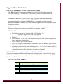
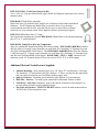
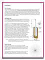
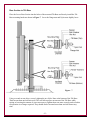
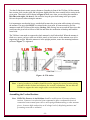
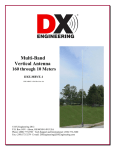
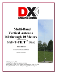
Multi-band Vertical Antenna 80 through 10 Meters DXE-MBVE-2 DXE-MBVE-2-INS-Revision 11e © DX Engineering 2012 P.O. Box 1491 ∙ Akron, OH 44309-1491 USA Phone: (800) 777-0703 ∙ Tech Support and International: (330) 572-3200 Fax: (330) 572-3279 ∙ E-mail: [email protected] Table of Contents Introduction 2 Features 2 Warning 2 Tools Required 3 DXE-MBVE-2 Parts List 3 Manual Updates 3 Suggested Parts Not Included 4 Additional Material Needed, Not Supplied 5 Installation 6 Site Selection Mounting Pipe Radial System 6 6 6 Assembly 7 Radial Plate to Mounting Pipe Attaching Ground Radial Wires to the Radial Plate Tilt Base to Mounting Pipe Vertical Base Section Base Section to Tilt Base Assembling the Vertical Sections Mating the Vertical Sections to the Tilt Base 8 9 10 11 13 14 18 Raising The Vertical 18 Assembling the UNUN Mounting Bracket 19 Installation of UNUN Assembly to Antenna 20 Feedline Connections 22 Tuning the Vertical 26 Guying a Vertical Antenna System 27 Optional Accessory Items 28 Technical Support and Warranty 31 -1- Introduction The DX Engineering MBVE-2 is a fast taper 33 feet high multi-band vertical antenna system. The vertical antenna operates from 80 meters through 10 meters using a good quality outboard customer supplied tuner. There are no traps, coils or linear loading elements to rob power. Designed with 6063 corrosion-resistant aluminum tubing and stainless steel hardware, this antenna is very durable and attractive. An extra tubing section is part of the design to provide final length adjustment from 33 feet to 36 feet if necessary. Features The DXE-MBVE-2 vertical antenna system includes the antenna elements, stainless steel element clamps, mounting plate assembly, Tilt Base, and stainless steel hardware. Full band coverage from 80 through 10 meters - Outboard customer supplied tuner required 33 to 36 ft overall height Includes the DXE Tilt Base Fast Taper from rugged base to sleek top for low wind resistance No Coils or Traps – Maximum Radiation Efficiency Power Handling up to 5 kW - built to last WARNING! INSTALLATION OF ANY ANTENNA NEAR POWER LINES IS DANGEROUS Warning: Do not locate the antenna near overhead power lines or other electric light or power circuits, or where it can come into contact with such circuits. When installing the antenna, take extreme care not to come into contact with such circuits, because they may cause serious injury or death. Overhead Power Line Safety Before you begin working, check carefully for overhead power lines in the area you will be working. Don't assume that wires are telephone or cable lines: check with your electric utility for advice. Although overhead power lines may appear to be insulated, often these coverings are intended only to protect metal wires from weather conditions and may not protect you from electric shock Keep your distance! Remember the 10-foot rule: When carrying and using ladders and other long tools, keep them at least 10 feet away from all overhead lines - including any lines from the power pole to your home. -2- Tools Required Two 7/16 wrenches, (one of them should be open-end) 5/16 inch, 3/8 inch, 7/16 inch, and 1/2 inch wrenches or 5/16 inch, 3/8 inch, 7/16 inch, and 1/2 inch sockets and drive Medium size flat blade screwdriver or 5/16 nut driver for the element clamps Medium size flat blade screwdriver or 1/4 nut driver for the smaller element clamp Tape measure and Felt-tip marker DXE-MBVE-2 Parts List Item: Tilt Base, 3/16" Laser Cut Stainless Steel DXE-SSVC-2P V-Saddle Kit Tilt Base, Mast Mount Channel DXE-TB-1 Tilt Base Plate 1/4-20 x 2" HH Bolt, full thread 1/4-20 x 1" HH Bolt, full thread 1/4" Flat Washer 1/4" Star Washer 1/4" Split Washer 1/4" Aluminum Spacer 1/4-20 Hex nut 1/4" Fender Washer, 1" OD 1/4-20 Flanged Nut 1/4-20 Nyloc nut 3/8 U-Bolt x 2" ID x 3.25" leg 2" Saddle for 3/8" U-Bolt 3/8-16 Hex Nut 3/8" Split Washer 3/8" Flat Washer Qty 1 2 1 1 4 1 6 2 4 4 6 4 2 4 2 2 4 4 4 Item: 2.000" x 0.058" x 36" Tube. 1.875" x 0.058" x 18" Tube. 1.875" x 0.058" x 36" Tube. 1.750" x 0.058" x 36" Tube. 1.625" x 0.058" x 36" Tube. 1.500" x 0.058" x 36" Tube. 1.375" x 0.058" x 36" Tube. 1.250" x 0.058" x 36" Tube. 1.125" x 0.058" x 36" Tube. 1.000" x 0.058" x 36" Tube. 0.875" x 0.058" x 36" Tube. 0.750" x 0.058" x 36" Tube. 0.625" x 0.058" x 36" Tube. 0.500" x 0.058" x 36" Tube. Element Clamps Drilled. Cut & drilled. (Slit one end) (Slit one end) (Slit one end) (Slit one end) (Slit one end) (Slit one end) (Slit one end) (Slit one end) (Slit one end) (Slit one end) (Slit one end) (Plain) Qty 1 1 1 1 1 1 1 1 1 1 1 1 1 1 12 Manual Updates Every effort is made to supply the latest manual revision with each product. Occasionally a manual will be updated between the time your DX Engineering product is shipped and when you receive it. Please check the DX Engineering web site (www.dxengineering.com) for the latest revision manual. -3- Suggested Parts Not Included DXE-UN-43 - Multi-Band UNUN for Vertical Antenna Systems The DXE-UN-43 DX Engineering Multi-Band Vertical UNUN built with proven MaxiCoreTM Technology is a matching device specifically designed for application with nonresonant vertical multi-band antennas. The DXE-UN-43 assures the best efficiency from your vertical multi-band antenna and transmission line/tuner installation. Using the DXE-UN-43 results in minimizing the additional transmission lines losses caused by SWR and allows your antenna to perform to its full potential. The DXE-UN-43 reduces the stresses on your equipment more efficiently than similar competitive products. By allowing your wide-range tuner to more easily match the antenna’s complex impedance, low frequency performance is improved over other devices currently available. DXE-UN-43 Features Full band coverage on 160-10 meters with an SWR under 1.5:1* *Customer supplied wide band tuner required. Impedance: 200 ohms to 50 ohms - optimized for 43 ft verticals Ratio: 4:1 Power Handling: 2 KW / 5 KW Peak - Handles rated power with minimal energy loss so there is no thermal related failure. Silver / Teflon® SO-239 input connector Two 1/4-20 feedpoint connection studs with Stainless Steel Flat Washers, Split Washers, Fender Washers & Wing Nuts High impact plastic, weather sealed NEMA-spec case - 2-1/2" x 4" x 4" inches (HxWxL) Shares the same mounting footprint as other similar competitive products, so it may be easily substituted in existing installations for superior performance. DXE-UN-BRKT - Mounting Bracket Kit for the DXE-UN-43 UNUN Custom laser cut patented Aluminum Mounting Plate including Custom Stainless Steel 90 degree Studded Element Clamps, Aluminum Spacers and Stainless Steel Hardware for mounting the DXEUN-43 to the DXE Multi-Band Vertical Antenna series. Parts List for the DXE-UN-BRKT Qty 1 4 4 4 2 2 2 Description Laser Cut Aluminum Mounting Bracket for the DXE-UN-43 # 6 x 1/2" long Stainless Steel Hex Head Bolts # 6 Flat Washer # 6 Nyloc Nut Custom Stainless Steel 90 degree studded Element Clamp 5/16" thick x 3/8" OD Aluminum Spacer for #10 Hardware # 10 Nyloc Nut -4- DXE-TCB-UNFK - Feed Point Connection Kit Two 1" wide x 9" long pre-drilled tinned copper braids for feedpoint connection to the vertical antenna system. DXE-RADP-3 Radial Plate (patented): Made from Laser Cut Stainless Steel with 20 Sets of Stainless Steel Radial Attachment Hardware. The DX Engineering Radial Plate is meant for those of you having a vertical antenna and want an easy, neat and effective way to connect those essential radial wires to your antenna system for the highest efficiency and strongest signals. DXE-SSVC-2P Stainless Steel V-Clamp: One required for mounting the optional DXE-RADP-3 Radial Plate to the antenna mounting pipe of 1" to 2" outside diameter. DXE-RADW Radial Wire Kits and Components: There are optional DX Engineering Radial Wire Kits available. DXE-RADW-500K/BD contains a 500 foot spool of 14 gauge copper stranded wire with black PVC insulation, 20 Terminal Lugs and 100 Steel or Biodegradable Lawn Staples. The DXE-RADW-1000K/BD Radial Wire Kit contains a 1,000 foot spool of 14 gauge copper stranded wire with black PVC insulation, 40 Terminal Lugs and 200 Steel or Biodegradable Lawn Staples. RADW-20RT, -32RT or -65RT contain 20 each radial wires with 1/4" terminal attached. These kits come in 20 Ft, 32 Ft, or 65Ft lengths. Additional Material Needed but not Supplied: Antenna Mounting - Steel mounting pipe, up to 2.0″ OD, 0.25″ wall thickness, 4 feet long. The standard 1-1/2" galvanized water pipe (with its 1.9" OD) is just fine for this application and can usually be found at your local home building supply store. Quik-Set Concrete - Mounting pipe installation (type depends on your landscape) DXE-P8A - Penetrox - To ensure good connection for aluminum element sections UMI-81343 - Anti-Seize compound - used on the threads of Stainless Steel Hardware to prevent galling and aid in proper tightening torque. Guy Rope and Anchors – DXE-GUY200-KIT contains 4 screw-in earth anchors and two 100 foot rolls of Dacron/polyester rope. -5- Installation Site Selection Select a mounting location clear from power lines, structures and other antennas by a minimum of 43 feet ( 33 + 10 foot safety rule). Consider overhead power lines, utility cables and wires. The further away the vertical is mounted from local noise sources or other metallic objects, which can re-radiate noise and affect the tuning, radiation pattern and SWR, the better. Determine the direction you want the antenna to tilt down and make sure there is adequate clearance (at least 43 feet). There should also be a clear diameter of about 35 feet from the antenna for the guying and radial systems that will extend away from the antenna. Mounting Pipe Use a customer supplied thick-walled galvanized steel mounting pipe at least 4 feet long. This will allow approximately 2 feet or more to be below ground and 20 inches above ground. A thick-walled steel pipe 1-3/4" OD to 2" OD maximum is recommended with a minimum thickness of 1/8" (1/4" preferred) should be used. The standard 1-1/2" galvanized water pipe (with its 1.9" OD) is just fine for this application and can usually be found at your local home building supply store. For permanent mounting, use a post-hole digger to make the hole deep enough to accommodate at least 2 feet of pipe and a couple inches of gravel at the bottom for drainage. Set the mounting pipe on the gravel, use the pre-mix concrete to fill around the pipe, adding water and mixing as you fill or mix the concrete first, then pour in the hole (depends on the type of concrete you purchase). Fill the hole until the concrete is level with the ground around it. Use a level on the mounting pipe as you fill the hole to be sure is vertically straight. Allow to set overnight. Your location, landscape and ground conditions may require different mounting solutions in order to have the steel mounting pipe and the vertical antenna in a secure position. Note: Galvanized steel, rather than aluminum, is much more suitable for mounting in concrete. Aluminum will quickly corrode due to incompatibility with the materials used to make concrete. Radial System The use of a radial system is a key requirement for a high performance quarter wave vertical antenna system. With a vertical antenna system, the radials are the second half of the antenna. The radials contribute to the radiation efficiency of the entire vertical antenna system. At a minimum, 20 radials, each 32 feet long, should be used with this antenna. Using 32 radials at 32 feet long is preferred and highly recommended. The extra radials help overcome unknown -6- poor-soil conditions, improve bandwidth, and ensure the best performance possible from the vertical antenna. DXE-RADW Radial Wire, a 14 gauge stranded copper with a black relaxed PVC insulation wire is suggested for the best results. The wire radials should placed as symmetrically as possible straight from the feedpoint around the vertical antenna and spaced evenly, regardless of how many radials are used. Do not cross or bunch any radial wires as this nullifies their effectiveness. If you have limited space, put in as many straight radials as you can. The radials must be connected to the shield of your feedline. The DXERADP-3 Stainless Steel Radial Plate is an ideal optional item which provides an excellent system for attaching radial wires to your vertical antenna system feedpoint. Radial wires can be laid on the roots of the grass using DXE-STPL Radial Wire Anchor Pins to hold them down. Using enough staples will ensure the wires will not be snagged by mowers, people, or animals. Grass will quickly overgrow the radials and it will be virtually impossible to see them. An article describing this process is available on the DX Engineering website in the Tech Info section. Radials can also be buried just under the surface by using a power edger to make a slit in the soil. Assembly The DXE-MBVE-2 shipping box contains the vertical tubing sections, an insulated U-channel, two 2" U-Bolts and Saddles, a backing plate, a Tilt Base with two stainless steel V-Clamps, 12 stainless steel element clamps, a black vinyl cap, and stainless steel hardware. Carefully un-box the antenna and separate the various parts. All of the element sections are 36" long. The 36" base section element (2" OD) and the 18" tube inside of it are both drilled to accept the feedpoint hardware. The added 18" section inside the base element section provides added wall strength for the base section. The vinyl cap for the top element section should be installed after assembly of the vertical is complete. Note: DXE-P8A Penetrox A Anti-Oxidant should be used between all antenna element sections. Penetrox is an electrical joint compound to affect a substantial electrical connection between metal parts such as telescoping aluminum tubing or other antenna pieces. It ensures high conductivity at all voltage levels by displacing moisture and preventing corrosion or oxidation. Note: UMI-81343 Never-Seez or DXE-NSBT8 Anti-Seize should be used on all clamps, bolts and stainless steel threaded hardware to prevent galling and to ensure proper tightening. -7- Note: The following assembly instructions are based on using a 2" OD Mounting Pipe, with the following options: DXE-RADP-3 Radial Plate, DXE-UN-43 UNUN, DXE-UN-BRKT Mounting bracket for the UNUN, and DXE-TCBUNFK Feedpoint kit for the UNUN Radial Plate to Mounting Pipe Install the optional DXE-RADP-3 Radial Plate on the 2" OD mounting pipe using an optional DXE-SSVC-2P stainless steel V-Clamps as shown in Figure 1. The standard 1-1/2" galvanized water pipe (with its 1.9" OD) is just fine for this application and can usually be found at your local home building supply store. Mount the Radial Plate so you have approximately 1" of space between the bottom of the plate and the ground level. This will allow easy access to install the radial wire hardware. The DXE-RADP-3 Radial Plate comes with 20 sets of stainless steel hardware for mounting the radial wires. Mount the plate as shown in relation to how the Tilt Base and the optional DXE- UN-43 UNUN are mounted. (For reference, Figure 15 shows the completed installation). Figure 1 - Optional DXE-RADP-3 Radial Plate Installation -8- Attaching Ground Radial Wires to the Radial Plate Using the 20 sets of supplied 1/4" stainless steel hardware (Bolt, Star Washer, Flat Washer, Split Washer, Nut) connect the optional ground radial wires to the DXE-RADP-3 Radial Plate as shown in Figure 2. Additional hardware kits are available (DXE-RADP-1HWK) that contain 20 sets of Radial Plate Hardware. There are optional DX Engineering Radial Wire Kits available. DXE-RADW-500K/BD contains a 500 foot spool of 14 gauge copper stranded wire with black PVC insulation, 20 Terminal Lugs and 100 Steel or Biodegradable Lawn Staples. The DXE-RADW-1000K/BD Radial Wire Kit contains a 1,000 foot spool of 14 gauge copper stranded wire with black PVC insulation, 40 Terminal Lugs and 200 Steel or Biodegradable Lawn Staples. RADW-20RT, -32RT or -65RT contain 20 each radial wires with 1/4" terminal attached. These kits come in 20 Ft, 32 Ft, or 65Ft lengths. Depending on the number of radial wires used, space them out evenly around the Radial Plate. The Radial Plate will accommodate up to 60 radial wires (60 laser drilled holes), or up to 120 radials if doubled up. Radial Wire Pattern Figure 2 - Radial Wire Hardware Installation -9- Tilt Base to Mounting Pipe Install the patented Tilt Base to the 2" OD mounting pipe using the included DXE-SSVC-2P stainless steel V-Clamps allowing approximately 4-1/2" clearance between the bottom of the tilt base plate, to the top of the DXE-RADP-3 Radial Plate as shown in Figure 3. The standard 1-1/2" galvanized water pipe (with its 1.9" OD) is just fine for this application and can usually be found at your local home building supply store. Make sure the Tilt Base and optional DXE-RADP-3 Radial Plate are oriented correctly for the direction you wish to tilt the antenna. See Figure 8 which shows the tilt action. Tighten the clamps evenly so the length of the exposed threads is approximately equal. Any clamp should be tightened evenly from side-to-side with an equal amount of thread above each nut. Figure 3 - 10 - Vertical Base Section The base section is made up of an insulated mounting channel, a mounting plate with hardware, two 2" x 3/8" U-Bolt assemblies and the base antenna section which is 2" OD thick wall, 36" long with a hole drilled at bottom end for the feedpoint hardware. Inside the base sections is an 18" length of 1.875" OD tubing that is also drilled at the feedpoint. These two sections must be aligned (feedpoint holes) so the feedpoint hardware can be installed Using Figure 4, attach the aluminum backing plate to the back of the insulated channel. The base hardware kit contains four 2" hex head bolts, four flat washers, four aluminum spacers, four split washers and four nuts. From the inside of the channel, insert a 2" hex head bolt with a flat washer through each of the middle four holes, through the backing plate. Put on the aluminum spacer, a split washer and a plain hex nut. Tighten firmly, but not enough to crush the insulated channel. Figure - 4 Using the 36" base section tube with the 18" section inside (and the feedpoint holes are aligned), install the 1/4-20 x 1" long feedline bolt through the hole in the base section from the inside, so the threads stick out. Put on a 1/4" star washer, 1/4" flat washer, then a 1/4-20 nut. Tighten securely. Add another 1/4" star washer, 1/4" flat washer and 1/4-20 nut, but do not tighten. The feedline from the UNUN attaches to this hardware. Figure 5 shows the completed feedpoint assembly. Figure 5 - 11 - Install the lower section to the insulated channel using the two 2" x 3/8" U-Bolts, two saddle clamps, four 3/8" flat washers, four 3/8" split washers, and four 3/8" hex nuts as shown in Figure 6. The base section tube should extend 1-3/4" beyond the bottom of the U-bolt clamp. The feedpoint hardware should be coming out on the left side as you look at the lower section as shown in Figure 6. When tightening, observe the split washers. When they fully seat (flatten out), the clamp is tight enough. Any clamp should be tightened evenly from side-to-side with an equal amount of thread above each nut. Figure 6 - 12 - Base Section to Tilt Base Place the Lower Base Section into the holes of the mounted Tilt Base and loosely install the Tilt Base mounting hardware shown in Figure 7. Leave the flange nuts and Nyloc nuts slightly loose. Figure - 7 Using a wrench or nut driver, securely tighten the two Nyloc Nuts at the bottom of the Tilt Base. Then loosen them one-half turn each. This will allow proper movement of the Tilt Base while raising or lowering the antenna. It is not necessary to tighten these nuts more securely unless further tilt operation is no longer required. They should not be loosened more than one-half turn at any time. - 13 - Test the tilt function to ensure proper clearances. Standing in front of the Tilt Base, lift the antenna base section, slide it to the right, and let it down slightly until the lower outside bolt is resting in the pivot point. Then slowly tilt as shown in Figure 8. Make sure when you are tilting the antenna to lift, slide to the right, and then tilt. Be careful to keep the pivot bolt resting in the pivot point. Reverse the process when raising the antenna. It is important to note that the lower, outside bolt becomes the pivot point while raising or lowering the antenna. This pivot bolt MUST be retained in the pivot point. It seems natural to push the antenna toward the Tilt Base while raising. Push up while raising, but not toward the base since this could cause the pivot bolt to lift out of the slot and allow the mechanism to bind up and bend the lower bolts. The Tilt Base is not made to support the whole antenna by itself when tilted. When the antenna is tilted over, ensure you have some sort of table, stand, or saw horse to set the antenna on to aid in supporting the weight. When the antenna is in the upright position, ensure the mounting hardware (reference Figure 7) is tightened. Figure - 8 - Tilt Action Note: A pair of sawhorses or ladders should be used to support the vertical sections during assembly with the tilt-base and whenever the vertical is tilted down. Do not allow the Tilt Base to support the entire weight of the vertical when horizontal. Assembling the Vertical Sections Note: DXE-P8A -Penetrox A Anti-Oxidant should be used between all antenna element sections. Penetrox is an electrical joint compound to affect a substantial electrical connection between metal parts such as telescoping aluminum tubing or other antenna pieces. It ensures high conductivity at all voltage levels by displacing moisture and preventing corrosion or oxidation - 14 - When assembling any telescoping aluminum tubing sections you should take the following steps: 1. Make sure the edges are smooth and not sharp. Deburring may be necessary, since burrs and shavings can occur on seams as well as edges. All surfaces need to be completely smooth to allow easy assembly of tubing sections. Caution Aluminum tubing edges can be very sharp. Take precautions to ensure you do not get accidentally cut. The raised particles and shavings that appear when the aluminum tubing is machined are referred to as burrs, and the process by which they are removed is known as deburring. Deburring is a finishing method used in manufacturing. Our aluminum tubing is machine cut on both ends and machine slit on one end. Although DX Engineering manufactured aluminum tubing is deburred, you should further assure that there are no ragged edges or protrusions. Use the DXE-22166 Slim Grip Deburring Tool, or the DXE-22600 Deburring Tool with Extending Handle and Extra Blades for this operation. 2. Clean the inside of the aluminum tubing to clear out any dirt or foreign material that would cause the aluminum tubing sections to bind during assembly. Do not use any type of oil or general lubricant between the aluminum tubing sections. Oils or general lubricants can cause poor electrical connections for radio frequencies. 3. Clean the outside of the aluminum tubing to clear any dirt or foreign material that would cause the clamps to malfunction during assembly. 4. The use of DXE-P8A Penetrox A is highly recommended. Penetrox A is an electrical joint compound which effects a substantial electrical connection between metal parts such as telescoping aluminum tubing or other antenna pieces. Using Penetrox A assures high conductivity at all voltage levels by displacing moisture and preventing corrosion or oxidation. 5. When assembling the aluminum tubing sections, ensure the area is clear of grass, dirt or other foreign material that could cause problems during assembly of the closely fitted telescoping sections. Assemble the vertical sections in an area that is flat and has sufficient room for the length of the antenna during assembly. Lay the tubing out in descending OD sizes. Orient the slits in the tubes toward the top of the antenna. The bottom 2" OD base section has the feedpoint connection hole at the bottom end. All the sections are 36" long. Each tubing section is inserted 6" into the next larger tube. Assembly is easier if the overlaps in the tubing sections are pre-marked. A dark color felt-tip marker works well. Measure and mark 6" from the end of each tube without the slit using a marker so it will be clearly visible. - 15 - Locate the 12 Element Clamps. Element Clamp DXE-ECL-040 - Element Clamp DXE-ECL-060 - Element Clamp DXE-ECL-10SS - Element Clamp DXE-ECL-12SS - Element Clamp DXE-ECL-16SS - Element Clamp DXE-ECL-20SS - Element Clamp DXE-ECL-24SS - Element Clamp Quantity 1 2 2 1 2 2 2 Figure 9 Refer to Figure 11 for element clamp sizes and locations. Slide the clamps over each section before putting them together. Align the clamps on each section facing the same direction. For final assembly, all the clamps should be positioned very close to the top of each section and the body of the clamp should be positioned between the slits as shown in Figure 9. Making sure dirt or grass does not adhere to the sections to be joined, insert the marked end of an element tube into the next sized element tube until the 6 inch mark on the element tube is even with the top of the larger element tube section. Position one of the element clamps at the very end, but not hanging over the edge. Make sure the body of the element clamp is positioned between the slits and tighten securely. Repeat the procedure with the marked end of the elements and the other element tubes using one of the element clamps as you work your way up the antenna length. Continue mating the smaller tubes inside the larger ones. Double-check the vertical sections you have just assembled. Using a felt tip pen, measure and mark the antenna sections as shown in Figure 10. Position one of the DXEECL-24SS clamps at the very end, but not hanging over. Make sure the body of the clamp is positioned between the slits and tighten securely. Repeat the procedure for the sections using the Element Clamps as shown in Figure 11. Figure 10 - 16 - Figure 13 - Finished Antenna Assembly - 17 - Mating the Vertical Sections to the Tilt Base CAUTION: Attempting final assembly without proper precaution can be dangerous. You should have someone help you steady the vertical antenna sections during mating with the base section. Note: A pair of sawhorses or ladders should be used to support the vertical sections during assembly with the Tilt Base and whenever the vertical is tilted down. Do not allow the tilt-base to support the entire weight of the vertical when horizontal. When the upper element sections are assembled together install the black vinyl cap in place at the top of the smallest element section. Mate the vertical sections to the base tube section by sliding the bottom 1-7/8" OD element of the vertical into the 2" OD base section element (which was previously mounted to the insulated channel) to the 6" mark you previously made. See Figure 11. The two sections will have a snug fit, so use a small amount of Penetrox A on the bottom section to make the fit easier. Slide the band clamp down between the slits, and tighten. Raising the Vertical DANGER: Make sure you have not inadvertently located the antenna underneath power lines. Residential power lines are often less than 40' high. Contact With Any Power or Utility Lines Can Be Lethal ! The tilt-base certainly makes it easier however, this antenna can be challenging to put up the first time or with gusty winds. If you have properly laid out your optional guy system in advance, it will help keep the vertical stable as you raise it – and stop you from going beyond vertical at the apex of the lift. Make sure the optional guy ropes are in the clear before you begin. While raising the antenna, keep a constant pulling pressure away from the Tilt Base. This will ensure that the pivot point bolt will not jump out of the pivot slot and cause the tilt mechanism to bind up and bend the bolts. Starting from the top of the antenna, walk it up slowly using an overhead hand-over-hand motion, maintaining a slow and steady pace. - 18 - The antenna mounting channel must be kept in parallel alignment with the tilt-base plate to prevent binding until it is positioned in the tilt-base. Once the antenna is vertical, lift and slide the antenna to the left toward the tilt-base mounting pipe to allow the two parts of the tilt-base to line up and drop down into the slots. Lightly tighten the top flange nuts on the tilt-base to hold the antenna. Note: As you raise the antenna to the vertical position, it’s important to maintain the parallel alignment between the antenna mounting channel and the Tilt Base backing plate to minimize binding. Make sure the lower tilt-base bolts are never excessively loose before raising. They should be first tightened securely and then backed off no more than 1/2 turn Once the antenna is fully raised, tighten the tilt base hardware (Top: two Nyloc Nuts and two Flange Nuts, Bottom: two Nyloc Nuts.) Assembling the UNUN Mounting Bracket Using the #6 hex head bolts, #6 flat washers, and #6 Nyloc nuts, attach the UNUN to the patented UNUN Bracket with the SO-239 connector facing down. Tighten the Nyloc Nuts so they are snug. Do not over tighten since the mounting tabs on the UNUN are plastic. Attach the custom Stainless Steel 90 degree Studded Element Clamps to the UNUN Bracket using the Aluminum Spacers and #10 Nyloc Nuts as shown in Figure 12. Snug the #10 Nyloc nuts just to the point that you can still rotate the custom studded element clamps. These Nyloc Nuts will be tightened later. Figure 12 - 19 - Installation of UNUN Assembly to Antenna Lower Section The completed UNUN and UNUN Mounting Bracket assembly are mounted to the antenna lower section. To allow easy installation of the UNUN Bracket to the lower base section, open the upper and lower custom studded element clamps as shown in Figure 13. Figure 13 Position the UNUN Mounting Bracket so the bottom element clamp is located between the feedpoint hardware and the U-Bolt as shown in Figure 14. Tighten the element clamps to hold the assembly in place. Figure 14 A: Clamps open, Clamp Ends inserted to go around Base Section B: Clamp Ends Starting to go behind Base Section C: Clamps surround Base Section - 20 - Once in position, re-insert the clamp ends into the worm drive of the clamps and using a flat blade screwdriver or nut driver, snug them up as shown in Figure 15. Note position of lower clamp is between the feedpoint hardware and the U-Bolt. Figure 15 - 21 - Position the UNUN so it faces forward. Tighten the Upper and Lower Studded Clamps and Tighten the Nyloc Nuts on the Upper and Lower Clamps Figure 16. Figure 16 Feedline Connections The DXE-UN-43 UNUN is attached to the feedline antenna connection using the DXE-TCBUNFK - UNUN Feed Point Connection Kit which contains two pre-drilled copper tinned braids for connection to the vertical antenna system. Both braids are 1" wide by 9" in length. Connect one braid from the antenna feedpoint located on the base section of the antenna to the terminal on the DXE-UN-43 UNUN closest to the Red "+" on the label as shown in Figure 17. Do not over tighten the wing nuts. Hand tighten them only, do not use pliers or other tools to over tighten the wing nuts. Connect the other 9" braid from the terminal on the DXE-UN-43 UNUN closest to the Black "▬" on the label to the closest radial wire bolt on the optional DXE-RADP-3 Radial Plate as shown in Figure 17. Route both braided cables as shown. - 22 - Note: Ensure the braid connection to the Radial Plate does not interfere with the tilting process. Figure 17 Your coaxial cable from the radio connects direct to the SO-239 connector on the DXE-UN-43 UNUN. Weatherproof this coaxial connection using TRM-06133 - Scotch® Super 33+ and DXE3M2155 - 3M Temflex™ 2155 Rubber Splicing Tape. - 23 - Figure 18a - Completed Base Assembly for Reference - 24 - Figure 18b - Completed Base Assembly for Reference - 25 - Tuning the Vertical Antenna System The use of a customer supplied, high quality, outboard tuner is required for any multi-band trapless vertical antenna system. The tuner should be capable of tuning the wide range of impedances presented by the antenna and coaxial cable at all the operating frequencies. Tuners of this type generally have a good quality variable roller inductor and at least one large variable capacitor for fine tuning. There are a number of outboard automatic antenna tuners available that are capable of tuning this type of high performance vertical antenna system. Tuners which are built into transceivers lack sufficient impedance tuning range for this type of high performance vertical antenna system. The actual impedance of the multi-band antenna is affected by local conditions, including proximity to structures, other antennas, number of radials, or personal preference for the mounting location. It may be necessary to adjust the top element section slightly longer or shorter, or to vary the length of the coaxial cable, if tuning to best SWR is not achieved with your tuner on all bands. The performance of this versatile, rugged antenna is highly dependent on the ability of your tuner to deliver a low SWR when tuned. Refer to your tuner user's manual for correct tuner operation. - 26 - Guying a Vertical Antenna System Guying of vertical antennas is always recommended for stability. However, if your area encounters severe wind velocities or icing conditions, simple guying will reduce the possibility of failure. Using the DXE-GUY-Kits, you can install four guy ropes starting approximately 1/2 the way up the vertical antenna system to ground level. Guying should be tightened just enough to permit the antenna to swing a few inches. The ends of the ropes are tied to the earth anchors that are screwed into the ground at about the same angle as the ropes will be. When using the Tilt Base, position the guy wires as shown below. This will make it easy to raise or lower the antenna and only one guy line needs to be loosened. The other guy lines will help guide the antenna on the way up. Depending on your antenna system, additional guys at points higher on the antenna may be required. Typical No Slip Knot for DXE-SYN-DBR Double-Braided Dacron Polyester Rope DXE-GUY200-Kit Side View The earth anchors are approximately 25 feet from the antenna base Note: Depending on wind and ice conditions, additional guying may be necessary. Top View - 27 - Optional Accessory Items DXE-UN-43 - UNUN - 4:1, High Power, for use with Non-Resonant Verticals DX Engineering high power transmission line transformers with Maxi-CoreTM Technology allow your antenna to perform to its full potential and reduces the stresses on your equipment more efficiently than similar competitive products. This UNUN is specifically designed for application with 43-foot non-resonant multiband antennas - assuring the best efficiency from your antenna and transmission line/tuner installation. This results in minimizing the additional transmission lines losses caused by SWR. It can be added to any existing 43-foot antenna installation, or used to replace an older competitive UNUN for a performance increase. 1.8 – 30 MHz operating range to cover popular amateur bands. Handles rated power with minimal energy loss so there is no thermal related failure. Ratio - 4:1 Impedance: 200 ohms to 50 ohms - optimized for 43 ft verticals Power Level – 2 KW / 5 KW PEP Frequency Range – 1.8 to 30 MHz Weatherproof NEMA enclosure Silver / Teflon SO-239 input connector 2-3/8" x 4" x 4" inches (HxWxL) DXE-UN-BRKT - UNUN Mounting Kit for Multi-Band HF Verticals (patented) This mounting kit allows you to mount a DXE-UN-43 UNUN at the base of any 43-foot Multi-Band vertical antenna. The aluminum mounting plate may be clamped to any 2" OD aluminum tubing element with the studded element clamps supplied. The UNUN is isolated by its plastic weather proof case, providing the simplest add-on installation. Works with the DXE-UN-43 UNUN, or similar competitive UNUNs and Baluns which use the same weatherproof NEMA case. Kit includes: Aluminum Mounting Plate Studded Stainless Steel Element Clamps Stainless steel mounting hardware DXE-TCB-UNFK - Feed Point Connection Kit, UNUN to Vertical Antenna This kit consists of two tinned copper braid straps for connection between a DXE-UN-43 UNUN and the ground radial system and feedpoint of a vertical antenna. The straps are the correct length to allow short, low inductance connections flexible for allowing use of a tilt base with the antenna. The length is 9" from center to center of the preformed 1/4" holes. If longer lengths are required, you may purchase the DXE-TCB-100 tinned copper braid by the foot for your own fabrication. Length: 9" center to center of the 1/4" holes Width: 1’’ Thickness: .045’’ Width and thickness may vary slightly as the flexible braid is stretched or compressed. DXE-RADP-3 - Radial Plate, Stainless Steel with 20 Sets of SS Radial Attachment Hardware The patented DX Engineering Radial Plate is meant for those of you that have or are building a quarter wave vertical antenna and who want an easy, neat and effective way to connect those essential radial wires and the coax to your vertical antenna for the lowest takeoff angle and strongest signals. DX Engineering Radial Plate is laser cut from tough stainless steel so that it has smooth edges, won’t corrode and will always look good. You will be proud of how good your installation looks. This plate will work perfectly with most commercially available vertical antennas such as the Hustler BTV series (4-BTV thru the 6-BTV), the SteppIR (BiggIR or SmallIR) or one of your own construction - 28 - DXE-SSVC-2P - Stainless Steel V-Clamp for steel pipe, 2 inch V-bolt This V-Clamp is made in one size that fits Steel tubing or pipe from 1" to 2'' OD as used in antenna construction. The supplied Vbolt is long enough to attach tubing to thick plates and is made with anti-corrosive properties. The special Stainless Steel saddle has serrated teeth will clamp to the pipe securely by biting into the surface. For this reason, it is not recommended for softer aluminum tubing or pipe. Ideal for fastening a radial plate and antenna mounting to a steel pipe. Used to clamp 1 to 2'' (OD) steel tubing or pipe Designed for attachments that don't require resistance to torque V-bolt and saddle made from high-strength 18-8* stainless steel The use of an anti-seize compound is HIGHLY recommended to achieve proper torque and prevent galling. DXE-MBV-ATU-1 - Multiband 43 ft Vertical Antenna Tuner Add-on Kit The DXE-MBV-ATU-1 is the perfect solution for the modest power (200 watts maximum) DXer who wants maximum performance on a 43 foot tall multi-band vertical antenna! Now you can hear and work the weak ones! Just install on your antenna mount and start operating. NO MANUAL TUNING! Now you can have full performance 80-10 meters with no coaxial cable mismatch loss! A no compromise system! A Bias Tee is included with this special package for supplying the 12 Vdc power through the coaxial cable from your radio shack to the remote tuner. Works on all DX Engineering, Zero-Five, MFJ and Hy-Gain 43 foot vertical antennas. Also on your own vertical antenna homebrew creation! Shown here in a typical installation with with optional radial plate and tilt base: DXE-MBV-ATU-1 Features: • MFJ-927 Remote IntelliTuner™ - 200 Watts • DXE-FCC050-H05-A Feedline Current Choke • DXE-SSVC-2P Stainless Steel Mounting V-Clamp • Custom Laser Cut Stainless Steel Bracket for Tuner and FCC • Bias Tee Power Injector for 12 Vdc • RG-8X 2 ft Coaxial Cable with PL-259 Connectors • 2 Tinned Copper Braids, 1" wide for connection to your optional Radial Plate • Feedline wire - 14 ga insulated stranded copper with Ring Terminal attached. UMI-81343, DXE-NSBT8 - Anti-Seize & Never-Seez An Anti-seize compound MUST be used on any Stainless Steel nuts, bolts, clamps or other hardware to prevent galling and thread seizure. Any of these products can be used for this purpose. *UMI-81343 Anti-Seize, 1 oz. Squeeze Tube *UMI-81464 Anti-Seize, 8.5 oz. Aerosol Can *DXE-NSBT8 Never-Seez, 8 oz. Brush Top *DXE-NMBT8 Never-Seez, 8 oz. Brush Top, Marine Grade * These products are limited to domestic UPS Ground shipping only DXE-P8A - Penetrox A Anti-Oxidant - 8 oz Squeeze Bottle Use Penetrox A electrical joint compound to affect a substantial electrical connection between metal parts such as telescoping aluminum tubing or other antenna pieces. Ensures high conductivity at all voltage levels by displacing moisture and preventing corrosion or oxidation. For Aluminum to Aluminum, Aluminum to Copper, or bare conductors. Not recommended for use with rubber or polyethylene insulated wire. 8 oz. squeeze bottle * This product is limited to domestic UPS Ground shipping only DXE-RADW - 500K or 1000K Radial Wire Kits and Components To achieve optimal performance with a ground-mounted vertical, install as many radials as possible. These bulk radial wire kits use insulated wire that is UV resistant, hard to see and lays down easily, unlike the wire that is commonly available at the big box stores. It will last much longer in contact with soil than bare wire. The DXE-RADW- 500K or 1000K kit provide everything you will need to build the perfect radial system! 500/1000 ft. spool of 14 AWG, stranded copper wire with vinyl insulation 20/40 lugs 100/200 radial wire anchor pins- Eliminating the need to bury your radials! Build up to 20/40 radials, 25 feet long DXE-RADW-500K Bulk Radial Wire Kit, 500 ft Spool of Wire, 20 Lugs, 100 Staples DXE-RADW-1000K Bulk Radial Wire Kit, 1000 ft Spool of Wire, 40 Lugs, 200 Staples - 29 - DXE-RADW-500KBD or 1000KBD - Bulk Radial Wire Kits and Components To achieve optimal performance with a ground-mounted vertical, install as many radials as possible. These bulk radial wire kit use insulated wire that is UV resistant, hard to see and lays down easily, unlike the wire that is commonly available at the big box stores. It will last much longer in contact with soil than bare wire. The biodegradable anchors allow easy installation of radial wires, and will degrade and disappear in a year or so when they are no longer needed. The DXE-RADW-500 or 1000KBD kit provides everything you will need to build the perfect radial system! 500/1000 ft. spool of 14 AWG, stranded copper wire with vinyl insulation 20/40 lugs 100/200 biodegradable radial wire anchor pins- Eliminating the need to bury your radials! Build up to 20/40 radials, 25 feet long DXE-RADW-500KBD Bulk Radial Wire Kit, 500 ft Spool of Wire, 20 Lugs, 100 Biodegradable Staples DXE-RADW-1000KBD Bulk Radial Wire Kit, 1000 ft Spool of Wire, 40 Lugs, 200 Biodegradable Staples DXE-STPL - Radial Wire Anchor Pins, 100/pack - No need to bury your radials! DX Engineering Radial Wire Anchor Pins are perfect for fastening radials below the grass line to eliminate the risk of damaging your radials during lawn maintenance. 100 count - 6'' Pins 11-Gauge DXE-STPL-100P Radial Wire Anchor Pins, 100/pack DXE-STPL-300P Radial Wire Anchor Pins, 300/pack DXE-STPL-100BD - Radial Wire Staple, Biodegradable, 3", 100 pack DX Engineering DXE-STPL-100BD is a 100-pack of 3” biodegradable anchors that are produced from recycled PLA (Polylactide Resin). Depending on the weather conditions, they will degrade in about a year. They are easily installed and will hold radial wires in place until lawn roots overtake them - and then disappear. Ecologically friendly! DXE-225RT-20 - Ring terminal 16-14 Wire Gauge, 1/4" hole/20-pk \his is a set of 20 ring terminals for AWG #14 to 16 wire with a clearance hole for a 1/4" bolt. These are the same crimp terminals supplied with the DXE Radial Wire Kits for #14 Radial and Antenna Wire. SUM-900031 - Automatic Wire Stripper/Crimper/Cutter, 24-10 Ga. Our DX Engineering wire stripper uses a spring-loaded design to make quick work of wires ranging from 24 to 10 gauge. Just insert the wire, squeeze the handle, and listen for the click. That’s the sound of another perfect wire stripping job performed in about 2 seconds- a fraction of the time it takes your pocket knife to do the same job. An adjustable wire length guide helps you make uniform strips, and a built-in wire cutter and crimper helps you complete your wiring job. Spring-loaded design Strips wires ranging from 24 to 10 gauge built-in wire cutter and crimper DXE-3M2155 - 3M Temflex™ 2155 Rubber Splicing Tape. Conformable self-fusing rubber electrical insulating tape. It is designed for low voltage electrical insulating and moisture sealing applications. For outdoor use, it should be protected from UV deterioration with an overwrap of DXE-33PLUS TRM-06133 - Scotch® Super 33+. Highly conformable super stretchy tape for all weather applications. This tape provides flexibility and easy handling for all around performance. It also combines PVC backing with excellent electrical insulating properties to provide primary electrical insulation for splices up to 600V and protective jacketing. DXE-22166 - Slim Grip Deburring Tool This Slim-Grip deburring tool allows quick and easy removal of burrs left after cutting or slitting aluminum tubing. Useful for most other deburring applications involving aluminum or steel. Slim-Grip design allows deburring in hard-to-reach locations. Consists of one replaceable blade, handle and pocket clip. Blades can be easily inserted and removed. DXE-22110 Replacement Blades for aluminum and steel available in packs of 10 - 30 - DXE-22600 - Deburring Tool with Extending Handle and 2 Blades Handy for cleaning burrs after cutting or drilling aluminum or steel. This rugged hand tool features an adjustable length blade holder to allow access to burrs deep inside tubing or other hard to reach places. Extremely versatile and handy. Includes one blade for aluminum and steel and one blade for cast iron and brass. Holder telescopes from 1⁄2" to 5" for long reach inside objects. Handle has storage compartment for spare blades. Blade can be inserted at 90° for deburring cross holes. DXE-RADW-20RT/-32RT/-65RT Pre-Assembled, Radial Wire, w/ 1/4" ring Terminals, 20 Pack The DXE-RADW Radial Wire Kits include the highest quality 14 gauge stranded copper wire with a relaxed black PVC insulation for easy installation of your radial system. The twenty pre-cut radial wires include 1/4" ring terminals professionally crimped on one end for quick and easy attachment to the radial plate. These Radial Wire Kits are designed for users of vertical antenna systems which have the need for a high quality radial system for optimum antenna performance. The 1/4" ring terminals are machine crimped for maximum grip. Soldering is not required for strength, but is recommended if installed in corrosive environments such as salt spray. Packed 20 Radial Wires per package - 14 gage, stranded copper wire - Black relaxed PVC insulation 1/4" Ring Terminal professionally crimped on each Radial Wire 3 lengths to choose from: 20 Ft (-20RT), 32 Ft (-32RT), 65 Ft (-65RT) DXE-RADW-20RT DXE-RADW-32RT DXE-RADW-65RT Package of 20 each 20 Ft Radials with 1/4" Ring Terminals Package of 20 each 32 Ft Radials with 1/4" Ring Terminals Package of 20 each 65 Ft Radials with 1/4" Ring Terminals DXE-GUY-Kits - Guying Kits for Vertical Antennas Some vertical manufacturers indicate their antennas do not need guying. During times of high winds or ice loading, some of these verticals may sustain damage or fail altogether. With the small amount of effort needed to install a four point guying system, the risk hardly seems worth taking. A four-point guying scheme provides the best mechanical advantage to reduce wind stress, regardless of direction. A four point guying system is recommended for use with a DX Engineering Tilt Base, because just one of the guy ropes has to be loosened when you tilt the vertical down. The remaining guys help stabilize the vertical in three directions when being raised. The guying kits are ideal for fixed or portable installations. DXE-GUY100-KIT DXE-GUY200-KIT DXE-GUY400-KIT DXE-GUY1000-KIT 4 - Heavy Duty screw-in earth anchors with eyelets 1 - 100 ft Roll - UV resistant, 3/32 Double-Braided Dacron Polyester Rope SYN-DBR-94-100 4 - Heavy Duty screw-in earth anchors with eyelets 2 - 100 ft Rolls - UV resistant, 3/32 Double-Braided Dacron Polyester Rope SYN-DBR-94-100 4 - Heavy Duty screw-in earth anchors with eyelets 4 - 100 ft Rolls - UV resistant, 3/32 Double-Braided Dacron Polyester Rope SYN-DBR-94-100 4 - Heavy Duty screw-in earth anchors with eyelets 1 - 1000 ft Roll - UV resistant, 3/32 Double-Braided Dacron Polyester Rope SYN-DBR-94-1000 Technical Support If you have questions about this product, or if you experience difficulties during the installation, contact DX Engineering at (330) 572-3200. You can also e-mail us at: [email protected] For best service, please take a few minutes to review this manual before you call. Warranty All products manufactured by DX Engineering are warranted to be free from defects in material and workmanship for a period of one (1) year from date of shipment. DX Engineering’s sole obligation under these warranties shall be to issue credit, repair or replace any item or part thereof which is proved to be other than as warranted; no allowance shall be made for any labor charges of Buyer for replacement of parts, adjustment or repairs, or any other work, unless such charges are authorized in advance by DX Engineering. If DX Engineering’s products are claimed to be defective in material or workmanship, DX Engineering shall, upon prompt notice thereof, issue shipping instructions for return to DX Engineering (transportation-charges prepaid by Buyer). Every such claim for breach of these warranties shall be deemed to be waived by Buyer unless made in writing. The above warranties shall not extend to any products or parts thereof which have been subjected to any misuse or neglect, damaged by accident, rendered defective by reason of improper installation, damaged from severe weather including floods, or abnormal environmental conditions such as prolonged exposure to corrosives or power surges, or by the performance of repairs or alterations outside of our plant, and shall not apply to any goods or parts thereof furnished by Buyer or acquired from others at Buyer’s specifications. In addition, DX Engineering’s warranties do not extend to other equipment and parts manufactured by others except to the extent of the original manufacturer’s warranty to DX Engineering. The obligations under the foregoing warranties are limited to the precise terms thereof. These warranties provide exclusive remedies, expressly in lieu of all other remedies including claims for special or consequential damages. SELLER NEITHER MAKES NOR ASSUMES ANY OTHER WARRANTY WHATSOEVER, WHETHER EXPRESS, STATUTORY, OR IMPLIED, INCLUDING WARRANTIES OF MERCHANTABILITY AND FITNESS, AND NO PERSON IS AUTHORIZED TO ASSUME FOR DX ENGINEERING ANY OBLIGATION OR LIABILITY NOT STRICTLY IN ACCORDANCE WITH THE FOREGOING. ©DX Engineering 2012 DX Engineering®, DXE®, DX Engineering, Inc.®, Hot Rodz™, Maxi-Core™, THUNDERBOLT™, Antenna Designer™, Yagi Mechanical™, and Gorilla Grip® Stainless Steel Boom Clamps, are trademarks of PDS Electronics, Inc. No license to use or reproduce any of these trademarks or other trademarks is given or implied. All other brands and product names are the trademarks of their respective owners. Specifications subject to revision without notice. - 31 -