1
OS-9® for Sandpoint Board
Guide
Version 4.7
w w w. r a d i s y s . c o m
Revision A • July 2006
Copyright and publication information
Reproduction notice
This manual reflects version 4.7 of Microware OS-9.
Reproduction of this document, in part or whole, by any means,
electrical, mechanical, magnetic, optical, chemical, manual, or
otherwise is prohibited, without written permission from RadiSys
Microware Communications Software Division, Inc.
The software described in this document is intended to
be used on a single computer system. RadiSys
Corporation expressly prohibits any reproduction of the
software on tape, disk, or any other medium except for
backup purposes. Distribution of this software, in part
or whole, to any other party or on any other system
may constitute copyright infringements and
misappropriation of trade secrets and confidential
processes which are the property of RadiSys
Corporation and/or other parties. Unauthorized
distribution of software may cause damages far in
excess of the value of the copies involved.
Disclaimer
The information contained herein is believed to be accurate as of
the date of publication. However, RadiSys Corporation will not be
liable for any damages including indirect or consequential, from
use of the OS-9 operating system, Microware-provided software,
or reliance on the accuracy of this documentation. The
information contained herein is subject to change without notice.
July 2006
Copyright ©2006 by RadiSys Corporation
All rights reserved.
EPC and RadiSys are registered trademarks of RadiSys Corporation. ASM, Brahma, DAI, DAQ, MultiPro, SAIB, Spirit, and ValuePro are
trademarks of RadiSys Corporation.
DAVID, MAUI, OS-9, OS-9000, and SoftStax are registered trademarks of RadiSys Corporation. FasTrak, Hawk, and UpLink are
trademarks of RadiSys Corporation.
†
All other trademarks, registered trademarks, service marks, and trade names are the property of their respective owners.
Ta bl e o f C on t e n ts
Chapter 1: Installing and Configuring OS-9®
8
9
9
9
10
10
11
11
12
12
14
15
15
15
16
18
18
18
22
23
27
30
34
34
34
35
36
7
Development Environment Overview
Requirements and Compatibility
Host Hardware Requirements (PC Compatible)
Host Software Requirements (PC Compatible)
Target Hardware Requirements
PersonalJava Hardware Requirements
Target Hardware Setup
Setting the Switches on the Target Board
Connecting the Target to the Host
Connecting To the COM Port
Ethernet Connection Only
Building the OS-9 Rom Image
Coreboot
Bootfile
Starting the Configuration Wizard
Creating and Configuring the ROM Image
Select System Type
Configure Coreboot Options
Configure System Options
\Network Configuration
Disk Configuration
Build Image
Transferring the ROM Image to the Target
Transferring the coreboot Image
Transferring the bootfile Image
bootfile from IDE Hard Drive
bootfile from Floppy Disk
OS-9 for the Sandpoint Board Guide
3
36
37
38
40
40
bootfile from BOOTP
Creating a Startup File
Example Startup File
Optional Procedures
Preliminary Testing
Chapter 2: Board Specific Reference
44
46
56
57
59
59
60
60
60
63
43
Boot Menu Options
Port Specific Utilities
PowerPC™ Registers Passed to a New Process
Vector Descriptions for PowerPC MPC8240
Error Exceptions: vectors 2-4 and 6-7
Vectored Interrupts: vector 5
User Trap Handlers: vector 7
System Calls: vector 12
OS-9 Vector Mapping
Configuring Booters
Chapter 3: Board Specific Modules
66
66
66
66
67
67
67
68
68
68
68
68
69
4
65
Low-Level System Modules
Configuration Modules
Console Drivers
Debugging Modules
Ethernet Driver
System Modules
Timer Modules
High-Level System Modules
Real Time Clock Driver
Ticker
Shared Libraries
Serial and Console Drivers
Serial Mouse and Keyboard Drivers
OS-9 for the Sandpoint Board Guide
69
70
Data Disk Drivers
Common System Modules List
Appendix A: Partitioning and Formatting Your Hard Drive
76
81
83
83
83
83
84
84
75
Partitioning Your Hard Drive
Formatting Your Hard Drive
OS-9 Partitioning Options
Create OS-9 Partition (1)
Set Active Partition (2)
Delete Partition (3)
Display Partition Information (4)
Change Extended DOS Partition to OS-9 Partition (5)
OS-9 for the Sandpoint Board Guide
5
6
OS-9 for the Sandpoint Board Guide
C h a p t e r 1 : I n s ta l l i n g a n d C o n f i g u r i n g
O S- 9 ®
This chapter describes installing and configuring OS-9® on the
Motorola Sandpoint 8240 target board. It includes the following
sections:
•
Development Environment Overview
•
Requirements and Compatibility
•
Target Hardware Setup
•
Connecting the Target to the Host
•
Building the OS-9 Rom Image
•
Transferring the ROM Image to the Target
•
Creating a Startup File
•
Optional Procedures
7
1
Installing and Configuring OS-9®
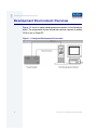
Development Environment Overview
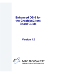
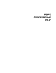
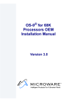
Figure 1-1 shows a typical development environment for the Sandpoint
board. The components shown include the minimum required to enable
OS-9 to run on PowerPC.
Figure 1-1 Sandpoint Development Environment
8
OS-9 for the Sandpoint Board Guide
1
Installing and Configuring OS-9®
Requirements and Compatibility
Host Hardware Requirements (PC Compatible)
Your host PC must meet the following minimum requirements:
•
300-400 MB of free disk space (an additional 235MB of free disk
space is required to run PersonalJava for OS-9)
•
an Ethernet network card
•
32MB of RAM (64MB recommended)
•
one free serial port
Host Software Requirements (PC Compatible)
Your host PC must have the following applications:
•
Windows 95, 98, ME, 2000, or NT
•
a terminal emulation program (such as Hyperterminal that
comes with Microsoft Windows 95, Windows 98 and Windows NT)
•
a BOOTP server, not supplied by Microware
OS-9 for the Sandpoint Board Guide
9
1
Installing and Configuring OS-9®
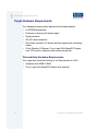
Target Hardware Requirements
Your Sandpoint target system requires the following hardware:
•
an EPROM programmer
•
Enclosure or chassis with power supply
•
Display terminal
•
RS-232 serial connectors
•
Disk drives and other I/O devices and their appropriate connecting
cables
•
3Com Etherlink III Ethernet, Cirrus Logic 5434 AlpinePCI Display
card, VGA monitor, keyboard, and mouse are optional
PersonalJava Hardware Requirements
Your target must have the following to run PersonalJava for OS-9:
10
•
Sandpoint with 32MB of RAM
•
Cirrus Logic 5434 AlpinePCI Display card (optional)
OS-9 for the Sandpoint Board Guide
1
Installing and Configuring OS-9®
Target Hardware Setup
The following sections detail how to set up the target board.
Setting the Switches on the Target Board
This section describes any switch settings that must be made on the
target board.
Note
Please refer to your Sandpoint Host Board User’s Manual for
information on hardware preparation and installation, operating
instructions, and functional descriptions prior to installing and
configuring OS-9 on your Sandpoint target board.
OS-9 requires the Sandpoint board to be run in either Mode 0: PPMC
With IDE or Mode 1: PPMC With Slots. This is configured by setting
switches S3 and S4 as shown on page 28 of the Sandpoint Host
Board User’s Manual. Note that if Mode 0 is used that PCI Slots 1 and
2 will not be available and if Mode 1 is used, the IDE interface will not be
available.
OS-9 further requires that the interrupt to the PMC be inverted by
setting switch S5 as shown on page 29 of the Sandpoint Host Board
User’s Manual.
OS-9 as shipped also requires that local I/O be shared with PCI Slot 3
as shown on page 30 of Sandpoint Host Board User’s Manual.
Because the local I/O device interrupt uses the Slot 3 line, PCI cards
that generate interrupts should not be installed in Slot 3. Slot 2 should
be used for cards that generate interrupts.
OS-9 for the Sandpoint Board Guide
11
1
Installing and Configuring OS-9®
Connecting the Target to the Host
The following sections detail how to connect the target machine to the
host machine.
Connecting To the COM Port
You need a terminal emulation program (such as Hyperterminal) and a
serial cable to establish the connection between the host PC and the
Sandpoint target machine.
Step 1.
With the target system powered off, use the serial cable to connect the
target’s COM port to an unused RS-232 COM port on your host PC.
You must also connect the target board and your host PC to a network
to use bootp (network booting).
Step 2.
On the Windows Desktop, select Start -> Programs ->
Accessories -> Hyperterminal.
Step 3.
Click the Hyperterminal icon and enter a name for your
Hyperterminal session.
Step 4.
Select an icon for the Hyperterminal session. A new icon is created with
the name of your session associated with it. Click OK.
Note
The next time you want to establish the same session, follow the
directions in Step 2 and select the icon you created in Step 3.
Step 5.
12
From the Phone Number dialog, select Connect Using and then
select the communications port to be used to connect to the target
system. Click OK.
OS-9 for the Sandpoint Board Guide
1
Installing and Configuring OS-9®
Step 6.
In the Port Settings tab, enter the following settings:
Bits per second = 9600
Data Bits = 8
Parity = None
Stop bits = 1
Flow control = None
Step 7.
Click OK
Step 8.
Go to the Hyperterminal menu and select File -> Properties.
Click on the Settings tab and select the following:
Terminal Keys
Emulation = Auto Detect
Backscroll Buffer Lines = 500
Step 9.
Click OK
Step 10. From the Hyperterminal window, select Call -> Connect from the
pull-down menu to establish your terminal session with the target
board. When you are connected, the bottom left of your Hyperterminal
screen displays connected.
Step 11. Turn on the target board. A power-on banner and DINK32_KAHLUA >>
prompt should appear on the display terminal connected to the board.
OS-9 for the Sandpoint Board Guide
13
1
Installing and Configuring OS-9®
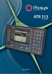
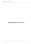
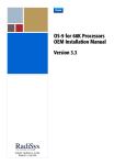
Ethernet Connection Only
The target system can also be configured with its own terminal, mouse,
and keyboard attached. In this configuration, communication between
the host and target is achieved through the Ethernet connection. Figure
1-2 shows this configuration.
Figure 1-2 Basic Sandpoint Development System—Ethernet Only
Ethernet
Target System
14
Host Development System
OS-9 for the Sandpoint Board Guide
1
Installing and Configuring OS-9®
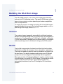
Building the OS-9 Rom Image
The OS-9 ROM Image is a set of files and modules that collectively
make up the OS-9 operating system. The specific ROM Image contents
can vary from system to system depending on hardware capabilities
and user requirements.
To simplify the process of loading and testing OS-9, the ROM Image is
generally divided into two parts: the low-level image, called coreboot,
and the high-level image, called bootfile.
Coreboot
The coreboot image is generally responsible for initializing hardware
devices and locating the high-level (or bootfile) image as specified by its
configuration. For example from a FLASH part, a harddisk, or Ethernet.
It is also responsible for building basic structures based on the image it
finds and passing control to the kernel to bring up the OS-9 system.
Bootfile
The bootfile image contains the kernel and other high-level modules
(initialization module, file managers, drivers, descriptors, applications).
The image is loaded into memory based on the device you select from
the boot menu. The bootfile image normally brings up an OS-9 shell
prompt, but can be configured to automatically start an application.
Microware provides a Configuration Wizard to create a coreboot image,
a bootfile image, or an entire OS-9 ROM Image. The wizard can also be
used to modify an existing image. The Configuration Wizard is
automatically installed on your host PC during the OS-9 installation
process.
OS-9 for the Sandpoint Board Guide
15
1
Installing and Configuring OS-9®
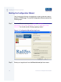
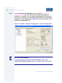
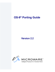
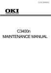
Starting the Configuration Wizard
The Configuration Wizard is the application used to build the coreboot,
bootfile, or ROM image. To start the Configuration Wizard, perform the
following steps:
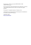
Step 1.
From the Windows desktop, select Start -> RadiSys ->
Microware OS-9 for PowerPC vX.Y -> Configuration
Wizard. You should see the following opening screen:
Figure 1-3 Configuration Wizard Opening Screen
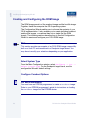
Step 2.
16
Select your target board from the Select a board pull-down menu.
OS-9 for the Sandpoint Board Guide
1
Installing and Configuring OS-9®
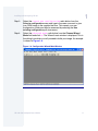
Step 3.
Select the Create new configuration radio button from the
Select a configuration menu and type in the name you want to give
your ROM image in the supplied text box. This names your new
configuration, which can later be accessed by selecting the Use
existing configuration pull down menu.
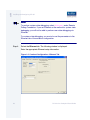
Step 4.
Select the Advanced Mode radio button from the Choose Wizard
Mode field and click OK. The Wizard’s main window is displayed. This is
the dialog from which you will proceed to build your image. An example
is shown in Figure 1-4.
Figure 1-4 Configuration Wizard Main Window
OS-9 for the Sandpoint Board Guide
17
1
Installing and Configuring OS-9®
Creating and Configuring the ROM Image
The ROM image consists of the coreboot image and the bootfile image.
Together, these files comprise the OS-9 operating system.
The Configuration Wizard enables you to choose the contents of your
OS-9 implementation. It also enables you to create individual coreboot
and bootfile images, or combine them into a single file (the ROM
image). The following sections describe how to use the Configuration
Wizard to create and configure your OS-9 ROM image.
Note
This section provides an example of an OS-9 ROM image successfully
built on a Host PC and transferred to a Sandpoint target board. You
may have to modify your selections depending on your application.
Select System Type
From the Main Configuration window, select Configure -> Sys ->
Select System Type. For the Sandpoint target board, use the
configuration Wizard’s default settings.
Configure Coreboot Options
More In
fo More
Informatio
n More Inf
ormation M
ore Inform
ation More
-6-
18
For More Information
You must have an EPROM programmer to create a coreboot image.
Refer to your EPROM programmer’s guide for instructions on loading
the coreboot image into the EPROM device.
OS-9 for the Sandpoint Board Guide
1
Installing and Configuring OS-9®
To create a new coreboot image, use the Configuration Wizard to
complete the following steps. Otherwise, continue to the Configure
System Options section.
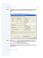
Step 1.
From the Main Configuration window, select Configure ->
Coreboot -> Main configuration.
Step 2.
Select the Debugger tab. The following window is displayed.
Figure 1-5 Coreboot Configuration—Debugger Tab
Step 3.
Under Select Debugger, select RomBug. This sets Ethernet as the
method for user state debugging. Select None if you do not want to
debug your system.
OS-9 for the Sandpoint Board Guide
19
1
Installing and Configuring OS-9®
Note
To perform system state debugging, select Ethernet under Remote
Debug Connection. If you set Ethernet as the method for system state
debugging, you will not be able to perform user state debugging via
Ethernet.
For system state debugging, you must also set the parameters in the
Ethernet tab of the coreboot configuration.
Step 4.
Select the Ethernet tab. The following window is displayed.
Enter the appropriate Ethernet setup information.
Figure 1-6 Coreboot Configuration—Ethernet Tab
20
OS-9 for the Sandpoint Board Guide
1
Installing and Configuring OS-9®
Note
Complete the Ethernet setup information only if you intend to boot your
system over a network or if you plan to use system state debugging.
Note
The addresses shown in Figure 1-6 are for demonstration only. Contact
your network administrator to obtain your Ethernet Setup information.
Step 5.
Select the Define ROM Ports tab. The following window is displayed.
Figure 1-7 Coreboot Configuration—Define ROM Ports Tab
OS-9 for the Sandpoint Board Guide
21
1
Installing and Configuring OS-9®
Step 6.
Select the Define Other Boot Options tab. The following window is
displayed.
Figure 1-8 Coreboot Configuration—Define Other Boot Options
Step 7.
Select Break-Enter System Debugger.
Step 8.
Click OK and return to the Main Configuration window.
Configure System Options
When you select Configure -> Bootfile -> Configure System
Options, the System Options window appears. This window contains
the Define /term Port tab, Bootfile Options tab, and MAUI® Options
tab. Use the default settings for your selections.
22
OS-9 for the Sandpoint Board Guide
1
Installing and Configuring OS-9®
Network Configuration
\
To use the target board across a network—once the target is
booted—complete the following steps:
Note
The IP addresses shown in this example are for demonstration only.
Contact your network administrator to obtain your IP Setup information.
Step 1.
Configure the Ethernet settings within the Configuration Wizard. To do
this, select Configure -> Bootfile -> Network
Configuration from the Wizard’s main menu.
OS-9 for the Sandpoint Board Guide
23
1
Installing and Configuring OS-9®
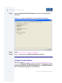
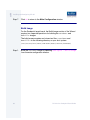
Step 2.
From the Network Configuration dialog, select the Interface
Configuration tab. From here you can select and enable the
interface. For example, you can select the appropriate Ethernet card
from the list of options on the left and specify whether you would like to
enable IPv4 or IPv6 addressing. Figure 1-9 shows an example of the
Interface Configuration tab.
Figure 1-9 Bootfile -> Network Configuration -> Interface Configuration
More In
fo More
Informatio
n More Inf
ormation M
ore Inform
ation More
-6-
24
For More Information
To learn more about IPv4 and IPv6 functionalities, refer to the
Using LAN Communications manual, included with this product CD.
OS-9 for the Sandpoint Board Guide
1
Installing and Configuring OS-9®
More In
fo More
Informatio
n More Inf
ormation M
ore Inform
ation More
-6-
For More Information
Contact your system administrator if you do not know the network
values for your board.
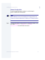
Step 3.
Once you have made your settings in the Network Configuration
dialog, click OK.
Step 4.
Select the DNS Configuration tab. The following window is displayed.
More than one DNS server can be added in this dialog box.
If your network does not use DNS, click Disable DNS, and move to
the Gateway tab.
If you have DNS available, click Enable DNS and type your host name
and domain.
Add DNS IP addresses by clicking on the box directly under DNS
Server Search Order, typing the IP address, and clicking the Add
button.
Step 5.
Select the Gateway tab. The following window is displayed.
Add new gateway address by clicking on the box, typing in the gateway
name, and clicking the Add button.
Step 6.
Select the SoftStax® Setup tab. The following window is displayed.
Step 7.
Click Enable SoftStax.
The options below represent daemons that can be automatically started
if you want to FTP or telnet from a PC to the OS-9 target. Start NFS
Client enables you to remote mount the target.
Note
This configuration is set for user state debugging on the target board.
For system state debugging, select Disable SoftStax.
OS-9 for the Sandpoint Board Guide
25
1
Installing and Configuring OS-9®
Step 8.
Select the SoftStax Options tab. The following window is displayed.
Step 9.
Click OK to return to the Main Configuration window.
26
OS-9 for the Sandpoint Board Guide
1
Installing and Configuring OS-9®
Disk Configuration
Step 1.
From the Main Configuration window, select Configure ->
Bootfile -> Disk Configuration.
Step 2.
Select the RAM Disk tab. The following window is displayed. The RAM
Disk tab enables you to create a RAM disk of any size for loading
modules onto the target.
Figure 1-10 Bootfile Configuration—RAM Disk Tab
OS-9 for the Sandpoint Board Guide
27
1
Installing and Configuring OS-9®
Step 3.
Select the IDE Configuration tab. The following window is displayed.
The IDE Configuration tab enables you to configure various drives for
the target.
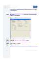
Figure 1-11 Bootfile Configuration—IDE Configuration Tab
Step 4.
28
Select the Floppy Configuration tab. The following window is
displayed. The Floppy Configuration tab enables you to configure a
floppy drive for the target.
OS-9 for the Sandpoint Board Guide
1
Installing and Configuring OS-9®
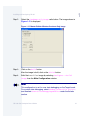
Step 5.
Select the Init Options tab. The following window is displayed. The Init
Options tab sets the configuration for OS-9 to initialize itself on the
target.
Figure 1-12 Bootfile Configuration—Init Options Tab
Step 6.
Select the Mshell option for the initial module name. This causes
OS-9 to start a console shell usable from your terminal window. Select
No Disk in the Initial Device Name section.
The tick rate is 100 and ticks per timeslice is set to 2.
The Parameter List box displays the commands that OS-9 executes at
system start-up.
OS-9 for the Sandpoint Board Guide
29
1
Installing and Configuring OS-9®
Step 7.
Click OK to return to the Main Configuration window.
Build Image
For the Sandpoint target board, the Build Image section of the Wizard
requires two separate operations for building the coreboot and
bootfile images.
The build process creates and stores two files—coreboot and
bootfile—in the following directory on your host system:
/mwos/OS9000/8240/PORTS/SANDPOINT/BOOTS/INSTALL/PORTBOOT/
Step 1.
30
Build the coreboot image by selecting Configure -> Build Image
from the main configuration window.
OS-9 for the Sandpoint Board Guide
1
Installing and Configuring OS-9®
Step 2.
Select the Coreboot Only Image radio button. The image shown in
Figure 1-13 is displayed.
Figure 1-13 Master Builder Window-Coreboot Only Image
Step 3.
Click on the Build button.
After the image is built, click on the Finish button.
Step 4.
Build the bootfiles image by selecting Configure -> Build
Image from the Main Configuration window.
Note
This configuration is set for user state debugging on the Target board.
For system state debugging, select ROMBug in Bootfile (p2init)
and deselect User State Debugging Modules under the Include
section.
OS-9 for the Sandpoint Board Guide
31
1
Installing and Configuring OS-9®
You must also complete the coreboot Ethernet information for system
state debugging.
Step 5.
Select the Bootfile Only Image radio button. The image shown in
Figure 1-14 is displayed.
Figure 1-14 Master Builder Window-Bootfile Only Image
Step 6.
Select the ROM Utility Set option.
Step 7.
Select the SoftStax (SPF) Support option.
Step 8.
Select the User State Debugging Modules option.
Step 9.
Click on the Build button.
Step 10. After the image is built, click on the Finish button.
32
OS-9 for the Sandpoint Board Guide
1
Installing and Configuring OS-9®
Note
After the coreboot and bootfile images are built and you are
returned to the Main Configuration window, you can select File ->
Save Settings before exiting the Wizard. This saves the settings for
your particular configuration.
OS-9 for the Sandpoint Board Guide
33
1
Installing and Configuring OS-9®
Transferring the ROM Image to the Target
For the Sandpoint target board, transferring the ROM Image from the
host to the target is done in the following two stages:
•
Transferring the coreboot Image
•
Transferring the bootfile Image
Transferring the coreboot Image
To transfer a coreboot image from your host to the EPROM device, you
must have an EPROM programmer.
More In
fo More
Informatio
n More Inf
ormation M
ore Inform
ation More
-6-
For More Information
The Configure Coreboot Options section contains steps for creating
a coreboot image. Refer to your EPROM programmer’s guide for
instructions on loading the coreboot image into the EPROM device.
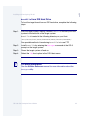
Transferring the bootfile Image
There are three options for transferring the bootfile image from the Host
to the Target, including the following:
34
•
bootfile from IDE Hard Drive
•
bootfile from Floppy Disk
•
bootfile from BOOTP
OS-9 for the Sandpoint Board Guide
1
Installing and Configuring OS-9®
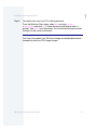
bootfile from IDE Hard Drive
To boot the target board from an IDE hard drive, complete the following
steps:
Step 1.
With the target system running, transfer bootfile file from your Host
system to the hard disk of the target system.
bootfile is located in the following directory on your Host:
/mwos/OS9000/8240/PORTS/SANDPOINT/BOOTS/INSTALL/PORTBOOT/
One possible method of transferring bootfile is to use FTP.
Step 2.
Install bootfile by entering the bootgen command at the OS-9
prompt on the target system.
Step 3.
Power the target system off and on.
Step 4.
Select the ide boot option in the OS-9 boot menu.
More In
fo More
Informatio
n More Inf
ormation M
ore Inform
ation More
-6-
For More Information
See the Utilities Reference manual for more information about the
bootgen utility.
OS-9 for the Sandpoint Board Guide
35
1
Installing and Configuring OS-9®
bootfile from Floppy Disk
To boot the target board from a floppy disk, complete the following
steps:
Step 1.
Copy bootfile from your host system’s hard disk to a floppy disk on
your host system. The floppy can be Window’s formatted.
bootfile is located in the following directory on your host:
/mwos/OS9000/8240/PORTS/SANDPOINT/BOOTS/INSTALL/PORTBOOT/
Step 2.
Install bootfile by entering bootgen -nb400 bootfile at the
OS-9 prompt in the Hyperterminal window.
Step 3.
Power the target system off.
Step 4.
Power the target system on.
Step 5.
Select the pf boot option in the OS-9 boot menu.
Note
If you use an OS-9 formatted floppy disk, select the fd option from the
OS-9 boot menu.
bootfile from BOOTP
To boot the target system using TFTP, you must use a BOOTP server.
The Microware OS-9 for PowerPC software package does not supply
a BOOTP server.
36
OS-9 for the Sandpoint Board Guide
1
Installing and Configuring OS-9®
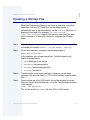
Creating a Startup File
When the Configuration Wizard is set to use a hard drive, or another
fixed drive such as a PC Flash Card, as the default device, it
automatically sets up the init module to call the startup file in the SYS
directory in the target (For example: /h0/SYS/startup,
/mhc1/SYS/startup). However, this directory and file will not exist
until you create it. To create the startup file, complete the following
steps:
Step 1.
Create a SYS directory on the target machine where the startup file
will reside (for example: makdir /h0/SYS, makdir /dd/SYS).
Step 2.
On the host machine, navigate to the following directory:
MWOS/OS9000/SRC/SYS
In this directory, you will see several files. The files related to this
section are listed below:
•
motd: Message of the day file
•
password: User/password file
•
termcap: Terminal description file
•
startup: Startup file
Step 3.
Transfer all files to the newly created SYS directory on the target
machine. (You can use Kermit, or FTP in ASCII mode to transfer these
files.)
Step 4.
Since the files are still in DOS format, you will be required to convert
them into the OS-9 format with the cudo utility. The following command
is an example:
cudo -cdo password
This will convert the password file from DOS to OS-9 format.
OS-9 for the Sandpoint Board Guide
37
1
Installing and Configuring OS-9®
More In
fo More
Informatio
n More Inf
ormation M
ore Inform
ation More
-6-
Step 5.
For More Information
For a complete description of all the cudo command options, refer to
the Utilities Reference Manual located on the Microware OS-9 CD.
Since the command lines in the startup file are system-dependent, it
may be necessary to modify this file to fit your system configuration. It is
recommended that you modify the file before transferring it to the target
machine.
Example Startup File
Below is the example startup file as it appears in the
MWOS/OS9000/SRC/SYS directory:
-tnxnp
tmode -w=1 nopause
*
*OS-9 - Version 3.0
*Copyright 2001 by Microware Systems Corporation
*The commands in this file are highly system dependent and
*should be modified by the user.
*
*setime </term
;* start system clock
setime -s
;* start system clock
link mshell csl
;* make "mshell" and "csl" stay in memory
* iniz r0 h0 d0 t1 p1 term ;* initialize devices
* load utils
;* make some utilities stay in memory
* tsmon /term /t1 &
;* start other terminals
list sys/motd
setenv TERM vt100
tmode -w=1 pause
mshell<>>>/term -l&
38
OS-9 for the Sandpoint Board Guide
1
Installing and Configuring OS-9®
More In
fo More
Informatio
n More Inf
ormation M
ore Inform
ation More
-6-
For More Information
Refer to the Making a Startup File section in Chapter 9 of the Using
OS-9 manual for more information on startup files.
OS-9 for the Sandpoint Board Guide
39
1
Installing and Configuring OS-9®
Optional Procedures
Preliminary Testing
Once you have established an OS-9 prompt on your target system, you
can perform the following procedures to test your system:
Step 1.
Type mdir at the prompt.
mdir displays all the modules in memory.
Step 2.
Type procs at the prompt.
procs displays the processes currently running in the system.
Step 3.
Test the networking on your system.
Select a host on the Ethernet network and run the ping utility. The
following example shows a successful ping to a machine called
solkanar.
$ ping solkanar
PING solkanar.microware.com (172.16.2.51): 56 data bytes
64 bytes from 172.16.2.51: ttl=128 time=0 ms
Step 4.
Test telnet.
Select a host machine that allows telnet access and try the OS-9
telnet utility. The following example shows a successful telnet to a
machine called delta.
$ telnet delta
Trying 172.16.1.40...Connected to delta.microware.com.
Escape character is '^]'.
capture closed.
OS-9/68K V3.0.3 Delta VME177 - 68060 98/12/24 14:41:51
User name?: curt
Password:
Process #101 logged on 98/12/24 14:41:56
Welcome!
***********************************************************
*
WELCOME TO DELTA - THE :OS-9 68K: MACHINE *
40
OS-9 for the Sandpoint Board Guide
1
Installing and Configuring OS-9®
Step 5.
Test telnet from your host PC to the target board.
From the Windows Start menu, select Run and type telnet
<hostname> and click OK. A telnet window should display with a $
prompt. Type mdir from the prompt. You should see the same module
listing as on the serial console port.
You have now created your OS-9 boot image and established network
connectivity with your OS-9 target system.
OS-9 for the Sandpoint Board Guide
41
1
Installing and Configuring OS-9®
42
OS-9 for the Sandpoint Board Guide
C h a p t e r 2 : B o a rd Sp e c if i c R e f e r e n c e
This chapter contains information that is specific to the Sandpoint
reference board from Motorola. It contains the following sections:
•
Boot Menu Options
•
Port Specific Utilities
•
PowerPC™ Registers Passed to a New Process
•
Vector Descriptions for PowerPC MPC8240
•
Configuring Booters
Note
This document describes using the Sandpoint with the Motorola
MPC8240 processor.
More In
fo More
Informatio
n More Inf
ormation M
ore Inform
ation More
-6-
For More Information
For general information on porting OS-9, see the OS-9 Porting Guide.
43
2
Board Specific Reference
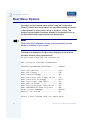
Boot Menu Options
You select your boot device menu options using the Configuration
Wizard. For each boot device option, you can select whether you want it
to be displayed on a boot menu, set up to autoboot, or both. The
autoboot option enables the device selected to automatically boot up
the high-level bootfile, bypassing the boot device menu.
Note
When using the Configuration Wizard, you should select only one
device for autoboot on your system.
Following is an example of the Boot menu displayed in the terminal
emulation window (using Hyperterminal):
OS-9000 Bootstrap for the PowerPC(tm)
Now trying to Override autobooters.
BOOTING PROCEDURES AVAILABLE ----- <INPUT>
Scan SCSI devices ---------------Boot FDC floppy -----------------Boot from PC-Floppy -------------Boot from Teac SCSI floppy drive Boot from SCSI PC-Floppy --------Boot from Viper tape drive ------Boot over Ethernet --------------Boot from SCSI(SCCS) hard drive -Boot embedded OS-9000 in-place --Enter system debugger -----------Restart the System ---------------
<ioi>
<fd>
<pf>
<fs>
<pfs>
<vs>
<eb>
<hs>
<bo>
<break>
<q>
Select a boot method from the above menu:
44
OS-9 for the Sandpoint Board Guide
2
Board Specific Reference
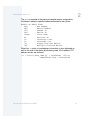
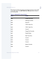
What you select for boot options in the configuration wizard determines
what modules are included in the coreboot image. Table 2-1 lists some
of the supported boot devices for OS-9:
Table 2-1 Supported Boot Methods
Type of Boot
Description
Boot from RBF hard disk
Boot from a standard SCSI hard
disk (hs).
Floppy Disk
Boot from floppy disk. You must
select if the floppy is controlled by
a Random Block File System
(RBF) (fd or fs) or PC File
System (pf or pfs).
Boot embedded OS-9
in-place
Boot OS-9 from FLASH (bo).
Copy embedded OS-9 to
RAM and Boot
Copy OS-9 from FLASH (if stored
there) to RAM and boot (lr).
OS-9 for the Sandpoint Board Guide
45
2
Board Specific Reference
Port Specific Utilities
The following port specific utilities are included:
46
•
dmppci
•
mouse
•
pciv
•
setpci
•
testpci
OS-9 for the Sandpoint Board Guide
2
Board Specific Reference
dmppci
Show PCI Information
SYNTAX
dmppci <bus_number> <device_number>
<function_number> {<size>}
OPTIONS
-?
Display help
DESCRIPTION
dmppci displays PCI configuration information that is not normally
available by other means, except programming, using the PCI library.
EXAMPLE
$ dmppci 0 11 1 0x40
PCI DUMP Bus:0 Dev:11 Func:1 Size:64
----------------------------------VID DID CMD STAT CLASS RV CS IL IP LT HT BI MG ML SVID SDID
--- ---- ---- ---- ----- -- -- -- -- -- -- -- -- -- ---- ---10ad 0105 0005 0280 01018f 05 08 0e 01 00 80 00 02 28 0000 0000
BASE[0] BASE[1] BASE[2] BASE[3] BASE[4] BASE[5] CIS_P
EXROM
-------- -------- -------- -------- -------- -------- -------- -------01000321 01000331 01000329 01000335 01000301 01000311 00000000 00000000
Offset 00 01 02 03 04 05 06 07 08 09 0a 0b 0c 0d 0e 0f
-----------------------------------------------------0000
ad 10 05 01 05 00 80 02 05 8f 01 01 08 00 80 00
0010
21 03 00 01 31 03 00 01 29 03 00 01 35 03 00 01
0020
01 03 00 01 11 03 00 01 00 00 00 00 00 00 00 00
0030
00 00 00 00 00 00 00 00 00 00 00 00 0e 01 02 28
OS-9 for the Sandpoint Board Guide
47
2
Board Specific Reference
mouse
Show Mouse Library Functions
SYNTAX
mouse <opts>
OPTIONS
-?
Display help
-s
Slow mouse
-f
Fast mouse
-r[n]
Set resolution to n
-p[n]
Set sample rate to n
-c[n]
Set scale factor to n
DESCRIPTION
mouse displays mouse status information.
48
OS-9 for the Sandpoint Board Guide
2
Board Specific Reference
EXAMPLE
$ mouse
Opening device
status = 0x08,
status = 0x08,
status = 0x08,
status = 0x08,
status = 0x08,
status = 0x08,
status = 0x28,
status = 0x28,
status = 0x28,
status = 0x08,
status = 0x28,
status = 0x08,
status = 0x28,
status = 0x08,
status = 0x09,
status = 0x08,
status = 0x0a,
status = 0x08,
OS-9 for the Sandpoint Board Guide
/m0
x =
x =
x =
x =
x =
x =
x =
x =
x =
x =
x =
x =
x =
x =
x =
x =
x =
x =
4,
6,
7,
7,
8,
7,
7,
7,
5,
2,
1,
2,
0,
1,
0,
0,
0,
0,
y
y
y
y
y
y
y
y
y
y
y
y
y
y
y
y
y
y
=
=
=
=
=
=
=
=
=
=
=
=
=
=
=
=
=
=
0
0
1
1
1
0
255 Y Negative
254 Y Negative
254 Y Negative
0
255 Y Negative
0
255 Y Negative
0
0 Left Button
0
0 Right Button
0
49
2
Board Specific Reference
pciv
PCI Configuration Space View
SYNTAX
pciv [<opts>]
OPTIONS
-?
Display help.
-a
Display base address information and size.
-r
Display PCI routing information.
DESCRIPTION
The pciv utility allows visual indication of the status of the PCIbus. This
utility is port dependent.
EXAMPLES
When using the pciv command with a Motorola PowerPC board, the
following information is displayed:
$ pciv
PowerPC 8240 Sandpoint Configuration Report
BUS:DV:FU VID DID CMD STAT CLASS RV CS IL IP
------------------------------------------------000:00:00 1057 0003 0006 20a0 060000 11 00 03 01
000:11:00 10ad 0565 0007 0200 060100 10 00 00 00
000:11:01 10ad 0105 0005 0280 01018f 05 08 0e 01
000:15:00 1013 00a8 0003 0000 030000 fc 00 12 00
000:16:00 10b7 5900 0007 0200 020000 00 00 13 01
50
MPC8240 Bridge/Mem Controller
Bridge Device [M]
Mass Storage Controller [M]
Display Controller [S]
Network Controller [S]
OS-9 for the Sandpoint Board Guide
2
Board Specific Reference
The pciv command in the previous example reports configuration
information related to specific hardware attached to the system.
DETAIL OF BASIC VIEW:
BUS
: Bus Number
DEV
: Device Number
VID
: Vendor ID
DID
: Device ID
CLASS
: Class Code
RV
: Revision ID
IL
: Interrupt Line
IP
: Interrupt Pin
[S]
: Single function device
[M]
: Multiple function device
When the -a option is used address information is also displayed as
well as the size of the device blocks being used. All six address PCI
address entries are scanned.
(C) [32-bit] base_addr[0] = 0x3efefe81 PCI/IO
0xbefefe80 Size = 0x00000080
OS-9 for the Sandpoint Board Guide
51
2
Board Specific Reference
The fields in the previous example are, from left to right, as follows:
•
prefetchable
•
memory type
•
address fields
•
actual value stored
•
type of access
•
translated access address used (shown on second line)
•
size of block (shown on second line)
When the -r option is used, PCI-specific information related to PCI
interrupt routing is displayed. If an ISA BRIDGE controller is found in the
system, the routing information is used. The use of ISA devices and PCI
devices in the same system requires interrupts to be routed either to
ISA or PCI devices. Since ISA devices employ edge-triggered interrupts
and PCI use devices use level interrupts, the EDGE/LEVEL control
information is also displayed. If an interrupt is shown as LEVEL with a
PCI route associated with it, no ISA card can use that interrupt. This
command also shows the system interrupt mask from the interrupt
controller.
Note
ISA and PCI interrupts cannot be shared.
52
OS-9 for the Sandpoint Board Guide
2
Board Specific Reference
setpci
Set PCI Value
SYNTAX
setpci <bus> <dev> <func> <offset> <size{bwd}>
<value>
OPTIONS
Display help
-?
DESCRIPTION
The setpci utility sets PCI configuration information that is not
normally available by other means other than programming using the
PCI library. The setpci utility may also be used to read a single
location in PCI space. Parameters include:
<bus>
= PCI Bus Number 0..255
<dev>
= PCI Device Number 0..32
<func>
= PCI Function Number 0..7
<offset>
= Offset value (i.e. command register offset = 4)
<size>
= Size b=byte w=word d=dword
<value>
= The value to write in write mode. If no value is
included, the utility is in read mode.
OS-9 for the Sandpoint Board Guide
53
2
Board Specific Reference
EXAMPLES
$ setpci 0 19 0 0x14 d
PCI READ MODE
------------PCI Value.....0x3bfedd00 (dword) READ
PCI
PCI
PCI
PCI
Bus.........0x00
Device......0x13
Function....0x00
Offset....0x0014
$ setpci 0 19 0 0x14 d 0x1234500
PCI WRITE MODE
-------------PCI Value.....0x01234500 (dword) WRITE
PCI Bus.........0x00
PCI Device......0x13
PCI Function....0x00
PCI Offset....0x0014
$
$ setpci 0 19 0 0x14 d
PCI READ MODE
------------PCI Value.....0x01234500 (dword) READ
PCI
PCI
PCI
PCI
54
Bus.........0x00
Device......0x13
Function....0x00
Offset....0x0014
OS-9 for the Sandpoint Board Guide
2
Board Specific Reference
testpci
Test PCI Value
SYNTAX
testpci
OPTIONS
-?
Display help
DESCRIPTION
The testpci utility tests all PCI library functions. To use this utility, you
must have a graphics card in the system. This utility shows how the PCI
library calls can be used.
EXAMPLE
$ testpci
Test PCI Library Calls Edition 2
_pci_search_device .......................ok....
_pci_next_device .........................ok....
_pci_get_config_data .....................ok....
_pci_find_device .........................ok....
_pci_find_class_code .....................ok....
_pci_read_configuration_byte .............ok....
_pci_read_configuration_word .............ok....
_pci_read_configuration_dword ............ok....
_pci_write_configuration_byte ............ok....
_pci_write_configuration_word ............ok....
_pci_write_configuration_dword ...........ok....
_pci_get_irq_pin .........................ok....
_pci_get_irq_line ........................ok....
_pci_set_irq_line ........................ok....
PCI LIBRARY TEST CONTAINS NO ERRORS.
OS-9 for the Sandpoint Board Guide
55
2
Board Specific Reference
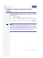
PowerPC™ Registers Passed to a New
Process
The following PowerPC registers are passed to a new process (all other
registers are zero):
r1
r2
r3
= stack pointer
= static storage (data area) base pointer
= points to fork parameters structure (listed in
f_fork)
r13 = points to the constant data of code area of the
module
Note
r2 is always biased by the amount specified in the m_dbias field of
the program module header which allows object programs to access a
larger amount of data using indexed addressing. You can usually ignore
this bias because the OS-9000 linker automatically adjusts for it.
56
OS-9 for the Sandpoint Board Guide
2
Board Specific Reference
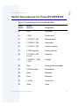
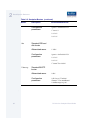
Vector Descriptions for PowerPC MPC8240
Table 2-2 Vector Descriptions for PowerPC MPC8240
Vector
Number
Related
OS-9 Call
Assignment
00
None
Reserved
01
F_IRQ
System reset
02
F_STRAP, F_IRQ
Machine check
03
F_STRAP, F_IRQ
Data access
04
F_STRAP, F_IRQ
Instruction access
05
F_IRQ (in epicirq)
External interrupt
06
F_STRAP, F_IRQ
(in ssm)
Alignment
07
F_STRAP, F_TLINK,
F_IRQ
Program
08
None
Floating-point unavailable
09
F_IRQ (in tkdec)
Decrementer
0A
None
Reserved
0B
None
Reserved
0C
F_SSVC
System call
0D
None
Trace
OS-9 for the Sandpoint Board Guide
57
2
Board Specific Reference
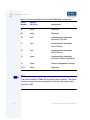
Table 2-2 Vector Descriptions for PowerPC MPC8240 (continued)
Vector
Number
Related
OS-9 Call
Assignment
0E
None
Reserved
0F
None
Reserved
10
ssm
Implementation dependent
instruction TLB miss
11
ssm
Implementation dependent
data TLB miss
12
ssm
Implementation dependent
data TLB miss
13
none
Implementation dependent
instruction address breakpoint
14
None
System management interrupt
21-31
None
Reserved
Note
The vector numbers in Table 2-2 are logical vector numbers. The actual
processor vectors can be computed by multiplying the logical vector
number by 256.
58
OS-9 for the Sandpoint Board Guide
2
Board Specific Reference
Error Exceptions: vectors 2-4 and 6-7
These exceptions are usually considered fatal program errors and
unconditionally terminate a user program. If F_DFORK create the
process or the process was debug attached with F_DATTACH, then the
resources of the erroneous process remain intact and control returns to
the parent debugger to allow a post-mortem examination.
A user process may use the F_STRAP system call to install an
exception handler to catch the errors and recover from the exceptional
condition. When a recoverable exception occurs, the process' exception
handler installed with the F_STRAP system call is executed with a
pointer to the process' normal static data and the current stack pointer.
Also, the process' exception handler will receive as parameters the
vector number of the error, the program instruction counter of where the
error occurred, and the fault address of the error if applicable. The
exception handler must decide whether and where to continue
execution. Programs written in the C language may use the setjmp
and longjmp library routines to properly recover from the erroneous
condition.
If any of these exception occur in system state during a system call
made by the process due to the process passing bad data to the kernel,
the process' exception handler is not called. Instead, the appropriate
vector error is returned from the system call.
Vectored Interrupts: vector 5
In general, the PowerPC processor family uses a single interrupt vector
for all external interrupts. However, most systems supporting the
PowerPC family use additional external logic to support more powerful
nested interrupt facilities. Hence, the vector numbers used by OS-9
device drivers are usually logical vectors outside of the range of the
hardware vectors listed above. The device drivers install their interrupt
service routines, via the F_IRQ system call, on the logical vector and
the kernel's dispatch code uses the external logic vector to identify the
source of the interrupt and call the associated interrupt service routine.
Interrupt service routines are executed in system state without an
associated current process.
OS-9 for the Sandpoint Board Guide
59
2
Board Specific Reference
Note
The F_IRQ system call may also be used to install exception handlers
on some non-hardware interrupt vectors. The above table lists the
exceptions that may be monitored using the F_IRQ facility. The installed
exception handler is called just like any other interrupt service routine
when the associated exception occurs.
User Trap Handlers: vector 7
This vector is used for dispatching user code into system state trap
handlers. The vector provides a mechanism for programs to switch
states and dispatch to a subroutine module to execute code in system
state.
System Calls: vector 12
This vector is used for service call dispatching to the OS-9 operating
system as well as user services installed using the F_SSVC service
request.
OS-9 Vector Mapping
This section contains the vector mappings and dual-port RAM
mappings for the MPC8240 processor.
The system modules siuirq and cpicirq map interrupts coming
from the SIU and CPM into the OS-9 vector table according to the
following mappings.
60
OS-9 for the Sandpoint Board Guide
2
Board Specific Reference
SIU (System Interface Unit) vectors are mapped starting at vector 0x40
in the order shown in the MPC8240 User’s Manual, and as shown in
the following table.
Table 2-3 Winbond PIC Interrupt Vectors
Vector
Source
0x40
System clock timer
0x41
Keyboard controller
0x42
Slave PIC
0x43
COM 2 Serial Port
0x44
COM 1 Serial Port
0x45
Unused
0x46
Floppy Disk Controller
0x47
Parallel Printer
0x48
Real Time Clock
0x49
Unused
0x4a
Unused
0x4b
Unused
0x4c
Mouse Controller
0x4d
Unused
OS-9 for the Sandpoint Board Guide
61
2
Board Specific Reference
Table 2-3 Winbond PIC Interrupt Vectors
Vector
Source
0x4e
Primary IDE Interface
0x4f
Secondary IDE Interface
The 8240 Embedded Programmable Interrupt Controller (EPIC) is set
up by OS-9 to operate in the direct mode (see Chapter 12 of the
MPC8240 User’s Manual. The EPIC interrupts which include PCI Slot
interrupts have their vectors mapped starting at 0x50 in the order shown
in Table 12-3 of the MPC8240 User’s Manual, and as shown in the
following table.
Table 2-4 EPIC Interrupt Vectors
62
Vector
Source
0x50
PCI Slot 1 Interrupt
0x51
PCI Slot 2 Interrupt
0x52
Winbond PIC Interrupt
0x53
PCI Slot 4 Interrupt
0x54
Unused
OS-9 for the Sandpoint Board Guide
2
Board Specific Reference
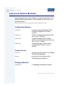
Configuring Booters
The following booters are available for the Sandpoint target platforms.
The abbreviated name and configuration parameters for the booters are
listed with recommended values (if any).
Note
The Sandpoint booters are located in coreboot.ml.
Table 2-5 Sandpoint Booters
Booter
Description
fdc765
Standard floppy disk
booter
Recommended Values
Abbreviated name:
"fd"
Configuration
parameters:
"port=0xFE0003f0"
"lun=0"
"si=0"
"ei=3"
fdc765
PC format floppy disk
booter
Abbreviated name:
OS-9 for the Sandpoint Board Guide
"pf"
63
2
Board Specific Reference
Table 2-5 Sandpoint Booters (continued)
Booter
Description
Recommended Values
Configuration
parameters:
"port=0xFE0003f0"
"lun=0"
"si=0"
"ei=3"
ide
Standard IDE hard
disk booter
Abbreviated name:
"ide"
Configuration
parameters:
"port=0xfe0001f0"
"si=0"
"ei=3"
"lsnoffs=2052"
llbootp
Standard BOOTP
booter
Abbreviated name:
"eb"
Configuration
parameters
"driver=lle509"
"bootfile=os9boot"
"maxbootptry=8"
p
64
OS-9 for the Sandpoint Board Guide
C h a p t e r 3 : B o a rd Spe c i f i c M o d u l e s
This chapter contains an overview of the board-specific low-level
system modules and the high-level system modules. Each listing
includes a brief description. The following sections are included:
•
Low-Level System Modules
•
High-Level System Modules
•
Common System Modules List
65
3
Board Specific Modules
Low-Level System Modules
The following low-level system modules are tailored specifically for the
Sandpoint 8240 target platform. These modules can be found in the
following directory:
MWOS/OS9000/8240/PORTS/SANDPOINT/CMDS/BOOTOBJS/ROM
Configuration Modules
cnfgdata
provides low-level configuration data
including configuration of a serial
console.
cnfgfunc
retrieves configuration parameters from
the cnfgdata module.
commcnfg
retrieves the name of the low-level
auxiliary communication port driver from
the cnfgdata module.
conscnfg
retrieves the name of the low-level
console driver from the cnfgdata
module.
Console Drivers
io16550
provides console services for the 16550
UART on the Sandpoint.
io8042
provides console services for the
VGA/keyboard combination.
Debugging Modules
usedebug
66
is a debugger configuration module.
OS-9 for the Sandpoint Board Guide
3
Board Specific Modules
Ethernet Driver
lle509_pci
provides network driver services for the
3Com Etherlink III Ethernet board.
System Modules
ide
is a low-level IDE booter module.
initext
is a user-customizable system
initialization module.
portmenu
retrieves a list of configured booter
names from the ROM cnfgdata
module.
romcore
provides bootstrap code.
romstart
resets vectors.
rpciv
shows information about devices on the
PCI bus.
Timer Modules
tbtimer
provides polling timer services using the
tblo and tbhi registers in the 8240
processors.
swi8timr
provides polling timer services using the
CPM timer of the 8240.
OS-9 for the Sandpoint Board Guide
67
3
Board Specific Modules
High-Level System Modules
The following OS-9 system modules are tailored specifically for your
Sandpoint 8240 platform. Unless otherwise specified, each module can
be found in a file of the same name in the following directory:
<MWOS>/OS9000/8240/PORTS/SANDPOINT/CMDS/BOOTOBJS
Real Time Clock Driver
rt146818
provides OS-9 access to the real time
clock.
Ticker
tk8253
provides the system ticker based on the
PowerPC decrementer.
Shared Libraries
picsub
provides interrupt enable and disable
routines to handle platform specific
interrupt controller issues for device
drivers. This module is called by all
drivers, and should be included in your
bootfile.
pcisub
provides PCI library functions for the PCI
bus.
Serial and Console Drivers
sc16550
provides support for the 16550 UART
serial port.
The descriptors provided for this driver
are named term, t1, and t2, and
are located in the following directory:
68
OS-9 for the Sandpoint Board Guide
3
Board Specific Modules
<MWOS>/OS9000/8240/PORTS/SANDPOINT
/CMDS/BOOTOBJS/DESC/SCCPM
scp87303
provides serial port support.
Serial Mouse and Keyboard Drivers
sc8042
allows VGA/Keyboard to be used as a
terminal. This uses the t0 descriptor.
sc8042k
is a keyboard driver used by MAUI.
sc8042m
is a mouse driver used by MAUI.
Data Disk Drivers
rb765
is a device driver for a floppy drive.
rb1003
is a device driver for the hard drive.
OS-9 for the Sandpoint Board Guide
69
3
Board Specific Modules
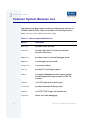
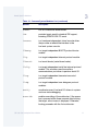
Common System Modules List
The following low-level system modules provide generic services for
OS9000 modular ROM. They are located in the following directory:
MWOS/OS9000/PPC/CMDS/BOOTOBJS/ROM
Table 3-1 Common System Modules List
70
Module
Description
bootsys
provides booter services.
console
provides high-level I/O hooks into low-level
console serial driver.
dbgentry
provides hooks to low-level debugger server.
dbgserv
is a debugger server module.
excption
is a service module.
fdc765
provides PC style floppy support.
fdman
is a target-independent booter support module
providing general booting services for RBF file
systems.
flboot
is a SCSI floptical drive disk booter.
flshcach
provides the cache flushing routine.
fsboot
is a SCSI TEAC floppy disk drive booter.
hlproto
allows user-state debugging.
OS-9 for the Sandpoint Board Guide
3
Board Specific Modules
Table 3-1 Common System Modules List (continued)
Module
Description
hsboot
is a SCSI hard disk driver booter.
ide
provides target-specific standard IDE support,
including PCMCIA ATA PC cards.
iovcons
is a hardware independent virtual console driver
that provides a telnetd-like interface to the
low-level system console.
llbootp
is a target-independent BOOTP protocol booter
module.
llip
is a target-independent internet protocol module.
llkermit
is a kermit booter (serial down loader).
llslip
is a target-independent serial line internet protocol
module. This modules uses the auxiliary
communications port driver to perform serial I/O
lltcp
is a target-independent transmission control
protocol module.
lludp
is a target-independent user datagram protocol
modules.
notify
coordinates use of low-level I/O drivers in system
and user-state debugging.
override
enables overriding of the autobooter. If the space
bar is pressed within three seconds after booting
the target, a boot menu is displayed. Otherwise,
booting proceeds with the first autobooter.
OS-9 for the Sandpoint Board Guide
71
3
Board Specific Modules
Table 3-1 Common System Modules List (continued)
72
Module
Description
parser
parses key fields from the cnfgdata module and
the user parameter fields.
pcman
is a target-independent booter support module
providing general booting services for PCF file
systems (PC FAT file systems).
protoman
is a target-independent protocol module manager.
This module provides the initial communication
entry points into the protocol module stack.
restart
restarts boot process.
romboot
locates the OS-9 bootfile in ROM, FLASH,
NVRAM.
rombreak
enables break option from the boot menu.
rombug
is a debugger client module.
scsiman
is a target-independent booter support module
that provides general SCSI command protocol
services
sndp
is a target-independent system-state network
debugging protocol module. This module acts as a
debugging client on the target, invoking the
services of dbgserv to perform debug tasks.
srecord
receives a Motorola S-record format file from the
communications port and loads it into memory.
swtimer
is a software timer.
OS-9 for the Sandpoint Board Guide
3
Board Specific Modules
Table 3-1 Common System Modules List (continued)
Module
Description
tsboot
is a SCSI TEAC tape drive booter.
type41
is a primary partition type.
vcons
is the console terminal pathlist.
vsboot
is a SCSI archive viper tape drive booter.
OS-9 for the Sandpoint Board Guide
73
3
Board Specific Modules
74
OS-9 for the Sandpoint Board Guide
Appendix A: Partitioning and
F o r m a t t i n g You r H a r d D r i v e
This appendix explains how to partition and format your hard drive with
one primary partition on your target system.
75
A
Partitioning and Formatting Your Hard Drive
Partitioning Your Hard Drive
This section explains how to partition your hard drive using the fdisk
command. The fdisk command displays and alters the partition table.
You should format your hard drive after you have partitioned it.
Note
Although OS-9 can be used without disk partitions, the use of partitions
is strongly recommended, even if only one partition is used. You cannot
perform hard disk booting if you do not partition your hard disk.
Note
OS-9 uses extended type41 partitions using the Random Block File
Manager (RBF) file system.The fdisk utility used to create partitions
allows a maximum of four primary partitions to be created. For
information on how to create more than one primary partition, refer to
the Utilities Reference Manual, located on the Microware OS-9 CD.
To create a partition on your target system, use the following steps:
Step 1.
76
Familiarize yourself with the fdisk command options and their uses,
as listed in Table A-1.
OS-9 for the Sandpoint Board Guide
A
Partitioning and Formatting Your Hard Drive
Table A-1 fdisk Command Options
Option
Description
-a [=] <num>
Makes partition <num> the active
partition.
-d [=] <dev>
Examines/changes device. Default = /hc.
-c
Forces terminal mode (cursers off).
-e
Includes partition information in display
mode.
-s
Displays the partition table.
Step 2.
At the OS-9 prompt, type tmode nopause. This allows you to view the
entire fdisk options window after step 3.
Step 3.
Create a partition using the fdisk utility. You must refer to the SCSI
raw drive when using fdisk. The following descriptors are available
when booting.
hcfmt<----- Master IDE drive on primary interface
hdfmt<----- Slave IDE drive
For example, to partition the primary IDE drive, you would enter the
following command at the OS-9 prompt:
fdisk -d=/hcfmt -e
Use the -i option to clear existing partitions from the board.
OS-9 for the Sandpoint Board Guide
77
A
Partitioning and Formatting Your Hard Drive
Note
hefmt is the descriptor for the Master IDE drive on the secondary
interface. hffmt is the Slave IDE drive on the secondary interface.
Note
For a complete explanation of related device descriptors, see the OS-9
Porting Guide.
Step 4.
The following partitioning options display:
1. Create OS-9000 partition
2. Set Active Partition
3. Delete partition
4. Display partition information
5. Change extended DOS partition to OS-9000 partition
Note
If your hard drive already has a partition you want to delete, select 3.
More In
fo More
Informatio
n More Inf
ormation M
ore Inform
ation More
-6-
78
For More Information
Refer to OS-9 Partitioning Options later in this Appendix for more
information on how to delete a partition.
OS-9 for the Sandpoint Board Guide
A
Partitioning and Formatting Your Hard Drive
Step 5.
Select 1. Create OS-9000 Partition. A prompt appears asking
you for the size of the partition you want (in cylinders). The default,
shown in brackets, is the maximum amount of cylinders available for
your partition on the hard drive. (You may have to hit <return> to view
all the information).
Note
If you currently have a partition on the drive (such as DOS), the default
size is the total number of remaining cylinders.
Display Partition Information
Current fixed disk device: /hcfmt@
Partition Status
Type
Start
End
Size
Enter the partition size in cylinders: [ 1022]
Note
It is important to note that one cylinder does not necessarily reflect
1MB. Enter the number of cylinders to allocate for the partition, not the
number of bytes.
Step 6.
The system determines the maximum amount of cylinders and uses
this as the default selection.
If you want the partition to be a portion of the total number of cylinders,
enter this number of cylinders instead.
Step 7.
Hit <return>
Step 8.
The following is displayed:
1. OS9000/386 type partition
2. Extended Type 41 partition
select partition type (1,2)...............:
OS-9 for the Sandpoint Board Guide
[
]
79
A
Partitioning and Formatting Your Hard Drive
Step 9.
Type 2 for Extended type 41 partition
Step 10. When the partitioning has completed, the display shows the display
partition information screen:
1. Create OS-9000 partition
2. Set Active Partition
3. Delete partition
4. Display partition information
5. Change extended DOS partition to OS-9000 partition
Step 11. Hit <esc>
Step 12. The partitioning is now complete. To exit the fdisk utility and save the
partition to the hard drive, hit the <esc> key. The following question is
displayed:
Want to save new partition information (y/n)?
Step 13. Type Y to save the partition information to disk. You return to the OS-9
prompt.
Step 14. Move on to Formatting Your Hard Drive.
80
OS-9 for the Sandpoint Board Guide
A
Partitioning and Formatting Your Hard Drive
Formatting Your Hard Drive
Before you format your hard drive, make sure that it is partitioned
correctly. See Partitioning Your Hard Drive in this Appendix for
information on how to perform this task. This section explains how to
format your hard drive using the format command.
More In
fo More
Informatio
n More Inf
ormation M
ore Inform
ation More
-6-
Step 1.
For More Information
For a complete description of all the format command options, refer to
the Utilities Reference Manual located on the Microware OS-9 CD.
Format the partitions using the correct descriptor for your hard drive.
Descriptor options include the following:
hc1-hc4---->Primary IDE Interface (Master)
hd1-hd4---->Primary IDE Interface (Slave)
he1-he4---->Secondary IDE Interface (Master)
hf1-hf4---->Secondary IDE Interface (Slave)
hs01fmt---->SCSI ID=0 Partition = 1
hs02fmt---->SCSI ID=0 Partition = 2
hs03fmt---->SCSI ID=0 Partition = 3
hs04fmt---->SCSI ID=0 Partition = 4
hs11fmt---->SCSI ID=1 Partition = 1
hs12fmt---->SCSI ID=1 Partition = 2
hs13fmt---->SCSI ID=1 Partition = 3
hs14fmt---->SCSI ID=1 Partition = 4
hs51fmt---->SCSI ID=5 Partition = 1
hs52fmt---->SCSI ID=5 Partition = 2
hs53fmt---->SCSI ID=5 Partition = 3
hs54fmt---->SCSI ID=5 Partition = 4
OS-9 for the Sandpoint Board Guide
81
A
Partitioning and Formatting Your Hard Drive
Step 2.
Enter the command format /hs01fmt -np -nv -r -vOS9000 to
format the hard drive. The following table shows the format specified
device options.
Table A-2 Format Specified Device Options
82
-be
create big-endian fs (ie: PPC)
-bo=<num>
use block offset of <num>
-c
enable command/interactive mode
-dd
double density disk
-ds
double sided disk
-h=<num>
disk has <num> heads
-i=<num>
use interleave of <num>
-le
create little-endian (ie: x86, ARM)
-m=<num>
put bitmap at block <num>
-np
no physical format
-nv
no physical verify
-o
do interleave optimization
-r
assume ready (don't ask)
-s=<num>
use spiral skew of <num>
-sd
single density disk
OS-9 for the Sandpoint Board Guide
A
Partitioning and Formatting Your Hard Drive
Table A-2 Format Specified Device Options (continued)
Step 3.
-ss
single sided disk
-to=<num>
use track offset of <num>
-t=<num>
disk has <num> tracks
-v=<name>
set volume name to <name>
-?
print this help message
Your hard drive is now partitioned and formatted, and the OS-9 prompt
returns.
OS-9 Partitioning Options
Create OS-9 Partition (1)
Creates OS-9 partitions. When partitions are created, you are prompted
for the size of the partition in terms of cylinders.
Set Active Partition (2)
Specifies which partition is bootable. If DOS is set as the active partition
and the system is reset, then DOS loads. To allow OS-9 to boot, you
must use the DOS version of fdisk to set the OS-9 partition to active.
If a boot manager is used, then set the Boot Manager as active.
Delete Partition (3)
Deletes partitions. Use the delete option with care. Extended partitions
may include any logical drives associated with them.
OS-9 for the Sandpoint Board Guide
83
A
Partitioning and Formatting Your Hard Drive
Display Partition Information (4)
Displays the partition tables. If the -e option is used, additional
information about the partition tables displays.
The extended/additional information includes:
Table A-3 Display Partition -e Option
Explanation
st
Start-flag (if 80 drive is startable)
s_head
Start head (byte)
s_cyl_blk
Start Cylinder block (word)
type
Partition type (word)
e_head
End head (byte)
e_cyl_blk
End cylinder block (word)
s_blk
Start block (LBA) (long-word)
size
Size of block (LBA) (long-word)
Change Extended DOS Partition to OS-9 Partition (5)
Converts an extended partition to an OS-9 partition. Extended partitions
may include logical drives.
84
OS-9 for the Sandpoint Board Guide