1
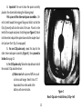
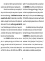
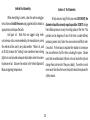
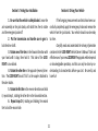
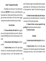
LOCK-RIGHT™ Performance Locker Installation Manual
Integral Carrier Axles—C-Clip and non-C-Clip Versions
Typical of Spicer®, Jeep®, G.M.® 10-, 12-bolt, Ford® 8.8-inch, Toyota® L.C., etc.
Introduction.................................................................................2
Background Information..............................................................3
Installations Covered....................................................................6
Preliminary Steps...........................................................6
Determination of Axle Type...........................................6
Differential Case Removal (thick ring gear)....................6
Disassembly of Differential Case...................................8
Inspection of the Parts...................................................9
Preparing Parts for Assembly.......................................10
Assembly of the Parts..................................................10
Differential Case Completion.......................................15
Case Final Assembly Into Vehicle.................................18
Differential Assembly Inspection.................................19
Vehicle Final Assembly.................................................19
Tire Diameters............................................................................21
Testing Your Installation..............................................................21
Driving Your Vehicle....................................................................22
Subsequent Disassembly............................................................22
Technical Assistance...................................................................23
Warranty Information................................................................23
1
WWW.RICHMONDGEAR.COM
Introduction
Welcome to the growing family of LOCK-RIGHT owners!
This manual will help you install your new LOCK-RIGHT automatic
100% full-locking differential. When the installation is complete,
your vehicle will have extreme traction! We trust that you will be
pleased with its performance and thank you for your confidence
in our products.
LOCK-RIGHT installation simply involves disassembling
and re-assembling the differential case, replacing a few parts in
the process. These instructions are detailed to the point that a
person who is reasonably familar with automotive work can install
a LOCK-RIGHT into a C-Clip integral carrier axle (and into certain
non-C-Clip variants) in about one hour, and into other integral carrier axles in about 2-1/2 hours; please read them carefully before
you start to be sure that you thoroughly understand them. Do not
attempt shortcuts unless you know exactly what you are doing.
These instructions also assume that you have the proper shop
manual for reference to instructions about axle shaft removal,
torque values, settings, clearances, etc. that apply to your particular vehicle. Our manual is a general guide to operations but
does not contain specific information for each vehicle.
Remember: This instruction manual is provided for your
convienience to assist you or your mechanic with the installation
of your new LOCK-RIGHT. However, the ultimate responsibility
for the success of your installation and the subsequent proper
operation of your vehicle rest with you, the vehicle owner.
When your installation is complete, you will have
a vehicle with significantly increased capabilities. For continued “fun in the sun,” operate it in a safe and responsible manner. Be sure to read and understand the driving information in the LOCK-RIGHT Vehicle Owner’s Manual!
2
44 axle, use a thrust block between the inside ends of the axle
shafts as a part of the end play adjustment. When installing a
LOCK-RIGHT, this block is re-used along with the original axles
so that the original end play adjustment does not change. However, if the original axles are changed to different original-type
axles, the block will continue to be used but the end play must
be re-adjusted (see the shop manual for the procedure). If the
axle is changed to another type that does not need end-play adjustment, such as a one-piece design, the thrust block may be
omitted. (In the Land Cruiser, the block is never used.)
A word about side gear thrust washers: All differentials
originally had a thrust washer under each side gear. Thrust washers are large in diameter and between about 1/32-inch (.031, or
0,76-mm) and 1/16-inch (.062, or 1,52-mm) thick. If either one
or both are missing from the original differential, obtain new
one(s) before proceeding!
Background Information
The differential case is the round housing inside the rear
axle assembly to which the ring gear is bolted and which contains
the differential spider and side gear assembly. It is installed in the
differential carrier, which is the housing that holds the case, drive
pinion gear, bearings, etc. The carrier may be removable (as part
of a “drop-out” unit, or third member), or it may be integral (as
a permanent part of the axle assembly, mounted in the vehicle).
This manual covers the integral carrier design, both C-Clip and
non-C-Clip versions.
The LOCK-RIGHT is designed to fit into standard open
differential cases only, not into limited-slip (clutch-pack) type
cases. If your vehicle contains a limited-slip unit you will need to
purchase a standard open differential case, thrust washers and
pinion shaft before proceeding.
A word about axle shaft thrust blocks: A few differentials, such as the Jeep® AMC-20 and the older 19-tooth Spicer®
3
The LOCK-RIGHT is designed to be used with a correct
thrust washer under each coupler, and failure to use this washer
is easy to observe during inspection and will void the warranty.
A word about C-Clips: Many integral carrier differentials have the axle shafts retained by C-Clips. These are semi-circular pieces of hardened steel, similar to a washer with one side
cut out, that fit into a groove in the end of the axle shaft and into
a pocket in the side gear. The axle shaft is held in place by the
pinion (spider gear) shaft. The LOCK-RIGHT is designed for many
of these axles, and their installation is covered in this manual.
This type of axle is the easiest in which to install a LOCK-RIGHT,
typically requiring about one hour for the procedure.
NOTE: The parts shown in the various figures are typical
and may not exactly depict your particular model.
LOCK-RIGHT Installations Covered
in This Manual
Integral carrier axles. Typical of these is Spicer®, Jeep®
AMC-20, G.M.® 10-, 12-, and 14-bolt, Ford® 7.5-inch and 8.8-inch,
Toyota® Land Cruiser; similar axles, with and without C-Clips.
Preliminary Steps
The following steps are only a general guide to preliminary operations used for preparing your vehicle for LOCK-RIGHT
installation. For detailed information, refer to your shop manual.
In general, the preliminary steps include:
a) Blocking the vehicle, putting transmission in neutral;
b) Loosening the wheel lug nuts (optional with C-Clips
and other axles);
c) Jacking up the axle; securely resting it on jack stands;
4
( ) = PARTS IN SOME MODELS
THRUST
WASHER
COUPLER
(SIDE GEAR)
DRIVER
STOP PIN;
SPACER
PINION
SHAFT(S)
(BLOCK)
BIAS
SRPINGS
Figure 1
LOCK-RIGHT Exploded View
5
DRIVER
COUPLER
(SIDE GEAR)
THRUST
WASHER
d) Removing the tires;
e) Disconnecting the brake lines and emergency brake
cables;
f) Pulling out one or both axles a few inches.
Section 1: Removal of the Differential Case
and Ring Gear Assembly From the Vehicle
(thick ring gear)
Summary of steps in this section:
1) Securely block and jack up vehicle
2) Pull out axle shafts by about six inches
3) Mark carrier and bearing caps
4) Observe ring gear backlash amount
5) Remove bearing caps
6) Remove differential case from carrier
7) Remove and mark bearing races
8) Remove ring gear
9) Install LOCK-RIGHT
Determination of Axle Type
1. Remove the differential cover and drain the oil.
2. Inspect to determine axle assembly type. If it is a
C-Clip design, proceed directly to Section 2 on page 8. If not,
continue with step 3 (next).
3. Determine if the ring gear is thin enough to be able
to pull the pinion (spider gear) shaft out past the teeth. If so,
proceed directly to Section 2 on page 8. If not, continue with
Section 1 (next).
6
1. Perform the operations listed below and as described in your shop manual that apply to your vehicle. The axle
shafts should be pulled out about six inches for differential case
removal.
2. Using a center punch, mark both the carrier and
bearing cap on the ring gear side with one punch mark each
and on the other side with two marks. The caps are not interchangeable, because each one is line-bored with the carrier.
These marks are very important to correct re-assembly!
3. Rock the ring gear back and forth to get a “feel” for
the amount of backlash present. This amount of rotation will be
re-checked when the differential case is installed to determine if
it has been done correctly.
4. Remove the bearing caps and then the differential case and shims from the carrier as described in the shop
manual (some axle designs may require the use of a carrier
spreader tool). Be sure to put a small grind mark on each shim or
tag them so that they can be replaced on the same side.
5. Remove the differential bearing race from the side
with one punch mark first. Put a very small grind mark on the
outside of it, or use a tag. Be sure that you can identify it for
proper re-assembly on the same side.
6. Remove the other bearing race.
7. Remove the ring gear from the case. It may need to
be tapped off with a brass mallet (see the shop manual). Mark it
so that it can be re-installed in the same rotational orientation as
when removed.
8. Proceed to Section 2 (next) for LOCK-RIGHT Installation.
7
pocket in the side gear by the pinion shaft. “Bump” each tire
inward slightly to free the clips; they will fall out to free up the
internal parts.
4. For installations with the differential case in the vehicle, leave the ring gear side axle bolted in place; pull out only
the other axle shaft about two inches.
5. Remove the spider gears, side gears, all washers, and
axle shaft thrust block (if used in your assembly).
Section 2: Disassembly of the Differential Case with thin
ring gear, and C-Clips (in the vehicle); also with thick ring
gear (case removed from vehicle)
Note: If the axle assembly is a C-Clip design or has a thin
ring gear, the differential case remains in the vehicle and the ring
gear side axle shaft does not need to be disturbed—it simply remains bolted in place and the LOCK-RIGHT installation is done by
only partially removing the opposite axle shaft.
1. Remove the pinion shaft retaining pin, using a long
punch. In the vehicle, the left bearing cap may need to be removed; for C-Clip differentials only, unscrew the bolt.
2. Remove the pinion shaft.
3. For C-Clip differentials only: The C-Clips are located in a groove in the end of each axle shaft and are held in a
Inspection of the Parts
NOTE: These steps are important. The LOCK-RIGHT utilizes your differential case, side gear thrust washers and pinion
shaft (plus the axle shaft thrust block, if used), and they must
be in excellent condition. The spider gears and washers are not
used. If the following inspection shows that anything is bad, buy
new parts from your dealer!
8
1. Thoroughly clean the differential case and wash remaining parts with solvent, then dry them.
2. Inspect the pinion shaft. Any noticeable grooves or
galling may weaken it and can also adversely affect the operation
of your new LOCK-RIGHT. If it is not in excellent condition, obtain
a new one.
3. Inspect the side gear thrust washers. They are important to the correct positioning of the LOCK-RIGHT parts. If
they are excessively worn or are cracked, obtain new ones. If
several thicknesses are offered, try to obtain the same size as the
old ones. NOTE: There should be TWO thrust washers of about
equal thickness, one under each side gear.
4. Inspect the thrust block (if used). Be sure that the
ends are smooth and not galled.
5. Inspect the case for any chips, cracks or similar
damage. Also inspect the bearings, if the case is out of the
vehicle. If the case or bearings look bad, replace them. However,
if you do, remember that the shims no longer will be correct; the
ring and pinion backlash and bearings pre-load will need to be
reset with a dial indicator as described in the shop manual.
LOCK-RIGHT Installation
Preparing the Parts for Assembly
1. Coat the teeth of the couplers and drivers, the large
center holes of the drivers, and both sides of the thrust washers
with medium grease. Also place a little grease in each of the two
window holes in each driver. The grease will help hold things in
place and assist with functioning until the gear oil circulates.
2. Place a shear pin into each window hole. It should
be about flush (Figure 2).
9
3. Place a spacer into the center of each driver, wide
end toward the teeth if not symmetrical (Figure 2).
4. Press a thrust washer (with grease added) onto the
back of each coupler.
5. Insert a small spring into each of the large springs
and add a little grease to the coils to hold them together. Set
them aside.
Assembly of the LOCK-RIGHT Parts into
the Differential Case
Summary of steps in this section:
1) Install Ring gear side coupler and washer
2) Install other coupler and washer
3) Install left C-Clip (C-Clips only)
4) Install left driver and spacer assembly
5) Install other driver (non C-Clip); or
6) Install other C-Clip (C-Clips only)
Figure 2
Install shear pins and spacers
10
1. Install a coupler and washer assembly in the ring
gear end of the differential case (over the axle splines if in the
vehicle). See Figure 3. Note that the couplers in some models
may have flats for clearance. If an axle shaft thrust block is used,
place it in the center of the second coupler now if the installation is being done in the vehicle. If not, it may be installed later.
2. Place the second coupler and washer assembly into
the other end of the differential case (Figure 3).
3. For C-Clip differentials only: Place a C-Clip with the
ends pointing down into the ring gear side axle shaft end groove
and pull the tire out sharply to seat the clip (Figure 3). Then,
carefully push the other axle into the second coupler splines until
the end of the axle shaft is even with the coupler surface. Keep
the coupler seated in the case. Note: The ring gear is removed
for clarity. Ordinarily, the differential case is in the vehicle and
the ring gear is in place.
Figure 3
Install couplers (and left C-Clip if so equipped)
11
4. Important! Be sure to have the spacers correctly
placed in the drivers before doing the following steps!
Pick up one of the driver-and-spacer assemblies. Orient its teeth toward the ring gear flange and hold it so that the
flats (if present) will clear the sides of the case. Place it on the
teeth of the coupler and press it into the grease (Figure 4). Reach
into the center and push the spacer down onto the coupler shoulder (and over the C-Clip, if so equipped).
5. For non-C-Clip axles only, repeat this step for the
other driver-and-spacer assembly (Figure 4), then proceed to
Section 3 on page 13.
6. For C-Clip axles only, follow the steps below to install
the second C-Clip and other driver.
a) Make a tool with a piece of stiff wire, such
as from a coat hanger. Bend it into a “U”
shape about four inches wide at the
bottom, with one-inch sides.
Figure 4
Non-C-Clip axles—Install drivers; C-Clip—left
12
b) Place the other driver assembly in the
differential case. Push it to the left, touching
the other driver (Figure 5).
c) Using the U-shaped wire between the
driver and coupler teeth, push its spacer
leftward into the center of the left driver to
help hold it temporarily in place.
d) Rotate both drivers with the left tire until
the C-Clip installation recess in the right
driver teeth is pointing out.
e) Tap the right tire inward, until the bottom
of the groove in the end of the axle shaft is
even with the surface of the coupler. Keep
the coupler seated in the case.
f) Slide the other C-Clip through the recess in
the teeth and into the groove in the axle
shaft end (Figure 5).
g) Pull the right tire out sharply to seat the
C-Clip.
Figure 5
C-Clip axles—install C-Clip and right driver
13
h) Rotate the right tire 1/4-turn until the
C-Clip ends are pointing downward, so that
it will not fall off.
i) Rotate the left tire to position both drivers
so that the large semi-circular recess in the
right driver is facing out.
j) Push the right driver to the right and into
the grease in the coupler teeth.
k) Through the semi-circular recess, push the
right spacer to the right, over the C-Clip and
axle shaft end.
Section 3: Differential Case Assembly
Completion (All Models)
1. Rotate the right driver until one of its long window
holes (containing a pin) faces out, and rotate the other driver
until one of its empty pin holes lines up with the first window
hole.
2. Push the pin out of the window hole and into the
pin hole in the opposite driver with a small pointed tool (Figure
6).
3. Place one end of a spring assembly (small spring inside the large one) into the window hole, behind the pin (Figure
7). Compress it with a small screwdriver and pop the bottom
into the window hole (Figure 8).
NOTE: These steps are for the differential case that has
been removed from the vehicle and is on the bench, as well as
for those remaining in the vehicle.
Summary of steps in this section:
a) Rotate drivers; align holes
b) Push shear pin into other driver
c) Install spring assembly
d) Repeat for other pins and springs
e) Push spacers outward
f) Install pinion shaft and retaining pin
14
Push on the bottom coils to be sure that the spring snaps in and
is seated all the way. Rotate the drivers and do the same procedure for each of the other three pins and springs.
4. Reach in through the recesses with your fingers and
be sure that the spacers are pushed outward onto the couplers.
5. Rotate the drivers so that the large recesses line up
with the pinion shaft holes in the differential case.
6. If an axle shaft thrust block is being used, push it
into the center of the assembly and line up the large hole with
the pinion shaft holes. If in the vehicle, push the right axle shaft
inward now, into the coupler splines, to move the block to the
center.
7. Carefully insert the pinion shaft into the hole and
guide it through the drivers, past the spacers (and through the
thrust block, if used). It should insert easily by hand. If not, tap
it in, being very careful not to get the inner end caught on something!
Figure 6
Push pins into opposite driver
15
Figure 7
Install spring assemblies in holes
Figure 8
Snap spring assembly into hole
16
Be sure to orient it so that its retaining pin hole will line
up with the hole in the differential case (Figure 9). If the pinion
shaft will not insert, or is hard to insert, be sure that the correct
thrust washers are being used and that the spacers are oriented with the widest side (opening) fitting down over the coupler
shoulder. Rotate the drivers and couplers back and forth to be
sure that they are not binding.
8. Install the pinion shaft retaining pin. If the pin is
solid, as opposed to a roll pin, slightly deform the metal on the
side of the hole to help hold it in place (see the shop manual).
For C-Clip Axles only: Screw in and tighten the bolt.
9. For differential cases out of the vehicle: The case
should still be on the bench after the preceding steps; install the
ring gear now and torque the bolts. Proceed to the next section.
Figure 9
Install pinion shaft, then pin
17
Assembly of Differential Case Into Vehicle
(thick ring gear; differential case
was removed from vehicle)
manual for the exact procedure.
6. Finish the installation of any remaining parts by
reversing the order of disassembly—in general, the axles/backing plates, brake lines, emergency brake cables, and tires. If
your vehicle uses an axle shaft thrust block, be sure that the
correct axle shims are in place at the outer ends of the axle
shafts. In these designs there should be little or no end play.
Also note that in some designs the last 1/8-inch or so of the backing plate installation may be a light press fit and the axle shaft
may appear to be hitting something; tap the outside end of the
axle shaft and it should go in.
1. Clean the axle housing interior, cover, mounting surface and drain plug.
2. Place the correct bearing races onto each end of the
differential case, ready to install.
3. If shims are used, locate them near the correct ends
of the case, ready to install.
4. Install the differential case in the carrier as described
in the shop manual. Generally, this will involve placing the differential case and correctly-located bearing races with one shim
into the carrier and then tapping in the shim on the other side,
or pressing the case in if the shims are already mounted under
the bearings. In some designs a spreader for the housing may be
required.
5. Replace the bearing caps in their marked positions
and torque the bolts to their correct value. Consult the shop
Assembly Inspection
1. Inspect your work. Look for anything that is not correct. Be sure that the drivers rotate back and forth smoothly,
stopping at the pinion shaft.
18
Use a light to see that the spacers (and thrust block, if
used) are in place and that the springs are working properly.
When the above installation steps are completed, all
the parts should be in exactly the same positions as they were
when the installation began. If the differential case has been
removed from the vehicle, the backlash and pre-load settings
should be unchanged from before and no further adjustments
will be needed. To be certain, rock the ring gear back and forth
to see if the backlash appears to be the same as it was prior to
the installation. If not, it will need to be reset with a dial indicator
as described in the shop manual. Rotate the ring gear one revolution to be sure that nothing is binding.
Your LOCK-RIGHT installation should now be complete. As a preliminary test only, prior to the final test on the
next page, rotate the tires back and forth (transmission out of
gear and drive shaft free). The drivers should randomly unlock
and “click” as the tires move. Note that the tires will NOT lock
together—this easy-unlocking characteristic is a unique feature
of the LOCK-RIGHT and is perfectly normal. Watch to be sure
that both sets of teeth engage and disengage. If they do, your
installation has probably been done correctly and your LOCKRIGHT is ready for its final test, described in Section 5 on page
21. Note that the clicking sound is much louder now than what
you will hear during driving because the cover is off and no oil is
present.
As an additional check to be sure that everything has
been installed correctly, use a small ruler, vernier caliper or
blade-type feeler gauge. The distance between the halves of
the LOCK-RIGHT, that is, between the two drivers, should be
about 5/32-inch (.152-inch, or 3,86-mm). The tolerance limits
are between .145-inch (3,68-mm) and .170-inch (4,32-mm). If
this distance is much over .170-inch, either the case is quite
worn or the thrust washers are missing or are too thin and the
problem should be corrected before proceeding further.
19
Vehicle Final Assembly
Section 4: Tire Diameters
When everything is correct, clean the axle housing gasket surface and install the cover using a gasket and/or sealant as
appropriate, and torque the bolts.
Add gear oil. Note that we suggest using medium-to-heavy oils as recommended by the manufacturer, unless
the vehicle will be used in very cold weather. Thicker oil, such
as 85-140, reduces the “clicking” noise sometimes heard during
tight turns and provides adequate lubrication when the assembly becomes hot. Also see the section in the Vehicle Operator’s
Manual regarding temperature.
To help assure a long life for your new LOCK-RIGHT, tire
diameters should be as nearly equal as possible. DO NOT change
the inflation pressure to vary the rolling radius of the tire! This
practice can be dangerous if one of the tires is under-inflated,
producing excess heat, faster tire wear and more difficult vehicle control. The best way to equalize the rotation is to measure
the circumference of all the tires, including the spare. Choose
ones that are within about 3/8-inch or less of each other (do not
change from side-to-side if they are radials). If one tire is much
more worn than the other one, they both should be replaced for
safety reasons.
20
Section 5: Testing Your Installation
Section 6: Driving Your Vehicle
1. Be sure that the vehicle is safely blocked. Leave the
axle assembly on the jack stands, with both tires free to rotate
and the emergency brake off.
2. Put the transmission and transfer case in gear to
lock the drive shaft.
3. Rotate one of the tires in the forward direction with
your hand until it stops, then hold it. That side of the LOCKRIGHT is now locked.
4. Rotate the other tire in the opposite (reverse) direction. The LOCK-RIGHT should “click” as the coupler attached to
the axle rotates.
5. Rotate the first tire in the reverse direction and hold
it; repeat step 3, rotating the other tire in the forward direction.
6. Repeat steps 2-4, rotating and holding the second
tire to lock the second side.
If the foregoing measurements and tests have been successfully completed, apply the emergency brake and remove the
vehicle from the jack stands. Your vehicle should now be ready
to drive.
Carefully read and understand the driving information
contained in the LOCK-RIGHT Vehicle Owner’s Manual! Safe and
effective use of your new LOCK-RIGHT-equipped vehicle depends
on knowledgeable operation, and this can only be done by understanding its characteristics before you start. Be careful, and
have fun!
21
piece of small wire (a paper clip works well) under the spring and
pop the bottom out. Push the shear pin out of the pin hole and
into the window hole. Repeat for the other three springs and
pins.
4. Position the case horizontally and push in the spacers so that they are in the middle of the drivers. If a thrust block
is used, push it into the right coupler splines.
5. Remove the driver and spacer opposite the ring
gear flange first and then remove the second driver.
6. Remove the couplers.
Section 7: Subsequent Disassembly
If something is not correct now or if you need to disassemble your LOCK-RIGHT in the future, we will briefly describe
the procedure here. We will assume that the case has a thin ring
gear and remains in the vehicle, or that it has a thick ring gear
and has been removed from the vehicle and is on the bench.
Non-C-Clip Axles
1. If the case will remain in the vehicle (thin ring gear),
pull out only the right axle shaft about two inches. Otherwise,
remove the differential case from the vehicle and place it in the
bench.
2. Remove the pinion shaft retaining pin and the pinion shaft.
3. Rotate the drivers until one of the right window
holes faces out. Push under the spring with a small sharp-pointed pick and pry the end up. Push a small screwdriver or bent
C-Clip Axles
1. Remove the pinion shaft retaining bolt and the pinion shaft.
2. Rotate the drivers until one of the right window
holes faces out. Push under the spring with a small sharp-pointed pick and pry the end up. Push a small screwdriver or bent
22
10. Remove the driver and spacer opposite the ring
gear flange first and then remove the second driver.
11. Remove the left C-Clip.
12. Remove the couplers.
piece of small wire (a paper clip works well) under the spring
and pop the bottom out. Push the pin out of the pin hole and
into the window hole. Repeat for the other three springs and
pins.
3. Move the right driver to the left, touching the left
driver.
4. Move the right spacer to the left, into the center of
the left driver. (Use the U-shaped wire tool.)
5. Rotate the left tire and both drivers until the C-Clip
installation recess in the teeth of the right driver is pointing
down.
6. Tap the right tire inward to release the C-Clip so
that it falls down, through the recess.
7. Rotate the left tire to rotate both drivers and allow
the C-Clip to drop out of the case.
8. Pull the right tire out about one inch.
9. Push the spacers into the centers of the drivers.
Section 8: Technical Assistance
If you have general questions, please contact your local
dealer for assistance. If your questions are of a more technical
nature, you may call RICHMOND GEAR TechLine: 1-xxx-xxx-xxxx
for further information.
Section 9: Warranty Information
The Warranty is contained in the Vehicle Owner’s Manual that is supplied with your new LOCK-RIGHT. Consult this
manual for complete warranty information.
23
IMPORTANT
If your differential case or thrust washers are excessively worn, your new LockRight Locker may not be able to operate as it was designed. Therefore, two easy measurements must be made before final assembly to assure that your new locker will function
properly. To make these measurements, proceed as follows:
1. Remove the existing spider gears, side gears and thrust washers from the
differential case, and thoroughly clean it.
2. Install the Lock-Right couplers with the existing thrust washers in each end of
the case.
3. Place the spacers onto the centers of the couplers (wide side toward the axle splines if not symmetrical), and hold them
there.
4. Install the pinion shaft; carefully guide it past the spacers as it is being inserted through the holes in the case.
5. Measure the gap between each spacer and the pinion shaft with a feeler gauge. This gap should be between .005-inch
and .020-inch, with not more than an .008-inch difference between the two.
If your numbers are within the limits specified, remove the parts and begin your installation. If your numbers are not within
these limits, check the thrust washers and the differential case. If they are excessively worn or are damaged, they may need to be
replaced before installing your new Lock-Right Locker.
If you have any questions, call PowerTrax Customer Service at 1.864.843.9275 (8AM-6PM ET) for further assistance.
24
WARNING!
IMPORTANT INFORMATION
Please Read Carefully
•Check lube level between scheduled lube changes to insure that proper lube
The following [WARNING!] and [CAUTION!] information is supplied to you for your
protection and to provide you with many years of trouble free and safe operation of your Richmond Gear product.
level is maintained. Inspect vent plug to insure it is clean and operating. Inspect
the tightness of mounting bolts, misalignment of connecting shafts, lube leakage, excessive heating, or any unusual noise or vibration.
Read ALL instructions prior to operating transmission and/or ring and pinion.
Injury to personnel, transmission or ring and pinion failure may be caused by
improper installation, maintenance or operation.
DANGER!
WARNING!
CAUTION!
•Serious personal injury may occur as a result of improperly performed maintenance, adjustments or repairs.
•It is dangerous to get under a jacked-up vehicle.
The vehicle could slip off the jack and fall on you. You
could be crushed. Never place any part of your body
under a vehicle that is on a jack. Never start or run the
engine while the vehicle is on a jack. If you need to
get under a raised vehicle, take it to a service center
where it can be raised on a lift.
•Do not attempt any of the maintenance, checks or repairs described on the following pages if you are not fully familiar with these or other procedures with
respect to the transmission, or are uncertain as to how to proceed. Have the
necessary work done by a properly equipped and qualified workshop.
•Always be extremely careful when working on the transmission. Always follow
commonly accepted safety practices and general common sense. Never risk
personal injury.
•Hot oil can cause severe burns.
Use extreme care
when removing lubrication plugs and when working
close to a unit that has been in operation.
25
(continued on next page)
CAUTION!
•Do not operate the transmission or ring and pinion without proper lube and correct amount.
In the event of the resale of any of the goods, in whatever form, Resellers/Buyers
will include the following language in a conspicuous place and in a conspicuous
manner in a written agreement covering such sale:
•For safe operation and to maintain the unit warranty,
when changing a factory installed fastener for any reason, it becomes the responsibility of the person making
the change to properly account for fastener grade, thread
engagement, load, tightening torque and the means of
torque retention.
•Mounting bolts should be periodically checked to ensure
that the unit is firmly anchored for proper operation.
The manufacturer makes no warranties or representations, express or implied, by operation
of law or otherwise, as to the merchantability or fitness for a particular purpose of the goods
sold hereunder. Buyer acknowledges that it alone has determined that the goods purchased
hereunder will suitably meet the requirements of their intended use. In no event will the
manufacturer be liable for consequential, incidental or other damages. Even if the repair or
replacement remedy shall be deemed to have failed of its essential purpose under Section
2-719 of the Uniform Commercial code, the manufacturer shall have no liability to Buyer for
consequential damages.
Resellers/Buyers agree to also include this entire document including the danger,
warnings and cautions above in a conspicuous place and in a conspicuous manner
in writing to instruct users on the safe usage of the product.
•These instructions are not intended to cover all details
or variations in equipment, nor provide for every possible contingency to be met in connection with selection,
installation, operation, and maintenance. Should further
information be desired or should particular problems
arise which are not covered sufficiently for the Buyer’s
purpose, the matter should be referred to Richmond Gear.
This information should be read together with all other printed information supplied by Richmond Gear.
26
NOTES:
27
AN AMERICAN LEGEND FOR OVER 50 YEARS
28