1
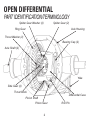
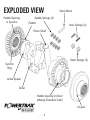
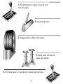
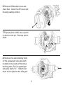
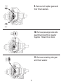
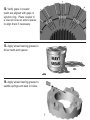
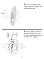
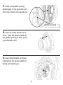
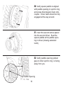
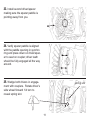
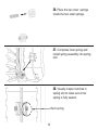
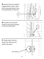
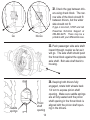
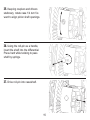
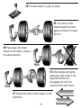
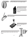
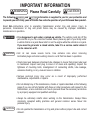
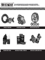
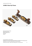
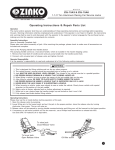
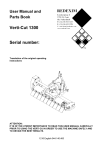
I N S TA L L AT I O N G U I D E
TM
Installation Guide
Contents
Page
Open Differential Part Identification & Terminology .........
2
Powertrax No-Slip Differential Exploded View ..................
3
Vehicle Preparation for Installation (steps 1 to 5) .............
4
Removal of Open Differential Parts (steps 6 to 11) ...........
5
Preparation of Parts to be Installed (steps 12 to 14) .........
7
Assembly (steps 15 to 37) ..............................................
8
Verification of Proper Assembly Test (steps 38 to 42) ....... 16
Finish Installation (steps 43 to 47) ..................................
17
Thoroughly read User Manual.
Traction output and resulting handling characteristics of your vehicle will be modified by installation.
Drive carefully and use caution under all on-road and off-road conditions.
OPEN DIFFERENTIAL
PART IDENTIFICATION/TERMINOLOGY
Spider Gear (2)
Spider Gear Washer (2)
Ring Gear
Axle Housing
Thrust Washer (2)
Bearing Cap (2)
Axle Shaft (2)
Yoke
Side Gear (2)
Thrust Block
Differential Case
Pinion Shaft
Pinion Gear
2
Roll Pin
EXPLODED VIEW
Paddle Opening
in Synchro
Check Block
Saddle Springs (8)
Paddle
Inner Springs (2)
Pinion Shaft
Outer Springs (2)
Synchro
Ring
Active Spacer
Driver
Paddle Opening in Driver
(Missing Extended Tooth)
Coupler
3
1. Put transmission in gear (or park), and
turn off engine.
2. Set parking brake.
3. Safeguard the vehicle from rolling.
4. Safely raise vehicle and
apply jack stands.
5. Put transmission in neutral and release parking brake.
4
6. Remove Differential cover and
drain fluid. Clean the diff cover and
housing sealing surface.
7. Expose pinion shaft; use a punch
to drive out roll pin. Remove pinion
shaft.
8. Remove the axle retaining bolts
for the passenger side axle shaft
located on the inside of the brake
backing plate. Pull out passenger
side axle shaft 2”-3”. Slide thrust
block to the right into the side gear.
5
9. Remove both spider gears and
their thrust washers.
10. Remove passenger-side side
gear/thrust block/thrust washer
together. Retain thrust block.
11. Remove remaining side gear
and thrust washer.
6
12. Verify gaps in coupler
teeth are aligned with gaps in
synchro ring. Place coupler in
a vise and use an active spacer
to align them if necessary.
13. Apply wheel bearing grease to
driver teeth and spacer.
14. Apply wheel bearing grease to
saddle springs and seat in holes.
7
15. Insert the thrust block into the
coupler that will go on the axle shaft
opposite the ring gear.
16. Insert the coupler into the ring
1
2
gear side of the case first. Insert
the coupler with thrust block into the
side opposite the ring gear.
8
17. Make sure paddle opening
(widest gap) in ring gear side synchro ring is facing out towards you.
Paddle Opening
18. Insert an active spacer into a
driver. Seat the spacer paddle at
the paddle opening in driver (missing extended tooth).
19. Insert driver/spacer as shown,
making sure the spacer paddle is
facing out towards you.
9
20. Verify spacer paddle is aligned
with paddle opening in synchro ring
and press driver/spacer down onto
coupler. Driver teeth should be fully
engaged all the way around.
21. Insert the second active spacer
into the second driver. Seat the
spacer paddle at the paddle opening in driver (missing extended
tooth).
22. Verify paddle opening (widest
gap) in other synchro ring is facing
away from you.
Paddle Opening
10
23. Install second driver/spacer
making sure the spacer paddle is
pointing away from you.
24. Verify spacer paddle is aligned
with the paddle opening in synchro
ring and press down on driver/spacer to seat on coupler; driver teeth
should be fully engaged all the way
around.
25. Wedge both drivers in engagement with couplers. Rotate driver’s
side wheel forward 1/4 turn to
reveal spring slot.
spring slot
11
26. Place the two inner springs
inside the two outer springs.
27. Compress inner spring and
install spring assembly into spring
slot.
28. Visually inspect notches in
spring slot to make sure inner
spring is fully seated.
check spring
12
29. Keeping both drivers wedged in
engagement with couplers, rotate
driver’s side wheel forward 1/2 turn
to reveal spring slot on other side.
30. Compress inner spring and
install the second spring assembly
into the second spring slot.
31. Visually inspect notches in
spring slot to make sure inner
spring is fully seated.
check spring
13
32. Check the gap between drivers using check block. The narrow side of the block should fit
between drivers, but the wider
side should not fit.
Go
If gap is incorrect, STOP and call
Powertrax Technical Support at
864-843-9275. There may be a
problem with your differential case.
No-Go
33. Push passenger side axle shaft
inward through coupler as far as it
will go. The axle shaft should push
the thrust block against the opposite
axle shaft. Bolt axle shaft back to
housing.
Saddle
springs
Pinion
shaft
opening
14
34. Keeping both drivers fully
engaged, rotate both wheels back
1/4 turn to expose pinion shaft
opening. Make sure saddle springs
are all fully seated and the pinion
shaft opening in the thrust block is
aligned with the pinion shaft opening in the drivers.
35. Keeping couplers and drivers
stationary, rotate case 1/4 turn forward to align pinion shaft openings.
36. Using the roll-pin as a handle,
insert the shaft into the differential.
Press hard while twisting to pass
shaft by springs.
37. Drive roll-pin into case/shaft.
15
38. Put transmission in gear (or park).
39. Turn driver’s side
wheel forward and hold
against driveline for steps
40 & 41.
HOLD
40. Passenger side wheel
should not be able to rotate in
the same direction.
HOLD
41. After sharply turning the
passenger side wheel in the
opposite direction (to
disengage the unit), the
wheel should rotate freely.
HOLD
42. Repeat the test for both wheels in both
directions.
16
43. Install differential cover with gasket sealant.
44. Add Richmond Synthetic
Gear Oil (75W-140) available
at your Authorized Richmond
Distributor.
45. Set parking brake.
46. Be sure transmission is in
gear or park.
47. Remove jack stands, lower vehicle, then remove
blocks.
17
IMPORTANT INFORMATION
WARNING
Please Read Carefully
CAUTION
CAUTION information is supplied to you for your protection and
The following WARNING and
to provide you with many years of trouble free and safe operation of your Richmond Gear product.
Read ALL instructions prior to operating transmission and/or ring and pinion. Injury to
personnel, transmission or ring and pinion failure may be caused by improper installation,
maintenance or operation.
DANGER
• It is dangerous to get under a jacked-up vehicle. The vehicle could slip off the
jack and fall on you. You could be crushed. Never place any part of your body under
a vehicle that is on a jack. Never start or run the engine while the vehicle is on a jack.
If you need to get under a raised vehicle, take it to a service center where it
can be raised on a lift.
WARNING
• Hot oil can cause severe burns. Use extreme care when removing
lubrication plugs and when working close to a unit that has been in operation.
• Check lube level between scheduled lube changes to insure that proper lube level
is maintained. Inspect vent plug to insure it is clean and operating. Inspect the
tightness of mounting bolts, misalignment of connecting shafts, lube leakage,
excessive heating, or any unusual noise or vibration.
• Serious personal injury may occur as a result of improperly performed
maintenance, adjustments or repairs.
• Do not attempt any of the maintenance, checks or repairs described on the following
pages if you are not fully familiar with these or other procedures with respect to the
transmission, or are uncertain as to how to proceed. Have the necessary work done
by a properly equipped and qualified workshop.
• Always be extremely careful when working on the transmission. Always follow
commonly accepted safety practices and general common sense. Never risk
personal injury.
CAUTION
• Do not operate the transmission or ring and pinion without proper lube and correct
amount.
• For safe operation and to maintain the unit warranty, when changing a
factory installed fastener for any reason, it becomes the responsibility of
the person making the change to properly account for fastener grade,
thread engagement, load, tightening torque and the means of torque retention.
• Mounting bolts should be periodically checked to ensure that the unit is
firmly anchored for proper operation.
• These instructions are not intended to cover all details or variations in
equipment, nor provide for every possible contingency to be met in
connection with selection, installation, operation, and maintenance. Should
further information be desired or should particular problems arise which
are not covered sufficiently for the Buyer’s purpose, the matter should be
referred to Richmond Gear.
In the event of the resale of any of the goods, in whatever form, Resellers/Buyers will include
the following language in a conspicuous place and in a conspicuous manner in a written
agreement covering such sale:
The manufacturer makes no warranties or representations, express or
implied, by operation of law or otherwise, as to the merchantability or
fitness for a particular purpose of the goods sold hereunder. Buyer
acknowledges that it alone has determined that the goods purchased
hereunder will suitably meet the requirements of their intended use. In no
event will the manufacturer be liable for consequential, incidental or other
damages. Even if the repair or replacement remedy shall be deemed to
have failed of its essential purpose under Section 2-719 of the Uniform
Commercial Code, the manufacturer shall have no liability to Buyer for
consequential damages.
Resellers/Buyers agree to also include this entire document including the danger, warnings
and cautions above in a conspicuous place and in a conspicuous manner in writing to
instruct users on the safe usage of the product.
This information should be read together with all other printed information supplied by
Richmond Gear.
HI-PERFORMANCE
HI-PERFORMANCE PRODUCTS...
PRODUCTS...
RING & PINIONS
REAR END LUBE
LIGHTENED GEARS
INSTRUCTIONAL VIDEOS
INSTALLATION KITS
SPOOLS & MINI-SPOOLS
TRANSMISSIONS
TRANSMISSION FLUID
CORD REELS
SHOPLIGHTS
QUICK CHANGE REAR ENDS
EXTREME TRACTION SYSTEMS
1208 Old Norris Road • P.O. Box 238 • Liberty, S.C. 29657
Phone: 864-843-9231 • Fax: 864-843-2964
www.richmondgear.com
822 1022 A
AMC 20
Open Differential
TM
P.O. Box 238, 1208 Old Norris Road, Liberty, S.C. 29657 • Tech Support (864)843-9275 • Fax (864)843-1276 • www.richmondgear.com