1
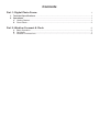
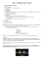
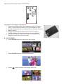
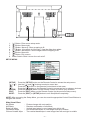
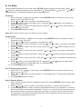
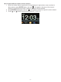
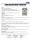
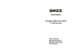
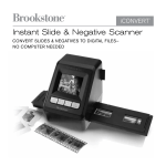
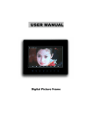
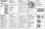
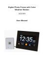
Digital Photo Frame with Color
Weather Station
XC0345
User Manual
Contents
Part 1: Digital Photo Frame
1.
2.
Technical Specifications..........................................................................................................1
Operations.................................................................................................................................1
A. Getting Started.....................................................................................................................1
B. Photo Mode.........................................................................................................................2
Part 2: Weather Forecast & Clock
1
6
A. Basic Operation...................................................................................................................6
B. Set Mode.............................................................................................................................7
C. Weather Forecast Icon........................................................................................................9
Part 1: Digital Photo Frame
1. Technical Specifications
Picture/Display
• 7-inch LCD Resolution: 480x234 pixels
Connectivity
• USB Host 2.0
Storage Media
• Memory Stick, Memory Stick Pro*, Memory Stick (Pro) Duo*, Multimedia Card, Secure Digital,
SDHC, USB Flash Drive
* Card adaptor not included
Convenience
• Photo format supported: JPEG (Up to 12 Mega pixels)
• OSD Languages: English, French, Denmark, Italian, Spanish, Netherlands
• IR remote control
• Power supply: AC-DC adaptor 110-220V / 12V1.5A
2. Operations
A. GETTING STARTED
The Digital Photo Frame with Color Weather Station was designed for easy set up. For best operation,
the following steps are required to be done in the proper sequence.
• Connect the adaptor power plug into the power socket of the Frame unit, then plug in the
power adaptor into the wall Jack.
Note: The socket-outlet shall be installed near the equipment and shall be easily accessible.
CAUTION:
Under the environment with electrostatic discharge, the operation of the captioned model
would be stopped or go to the initialisation stage. Just follow the instruction described in this
manual to set the function again for normal operation.
Slide the switch in the side panel of the digital photo frame to turn on the unit and use below IR remote
control to operate it.
There are two icons in power up screen represent for two operation modes – PHOTO MODE and
WEATHER FORECAST & CLOCK MODE. Press [ ] or [ ] button on the IR remote control or on
the top panel to select those modes.
~1~
Key layout of IR remote control is shown below.
IR remote control battery replacement:
1. Remove the Battery Holder by pressing the retaining clip sideways (1) and pulling the holder out (2) (see diagram at right);
2. Note the orientation of the old battery before removing it from the
Battery Holder;
3. Remove old battery and replace with a new 3-volt lithium
CR2025 battery in the same orientation as the old battery;
4. Reinsert the Battery Holder into the slot in the bottom of the
Remote Control until it locks into place.
B. PHOTO MODE
• Press [ENTER] button to enter photo viewer mode
• Press [ENTER] button to view full screen photo
• Press [
] button to begin a four-image slide show
~2~
1
2
Table 1 Photo mode functions table with remote control
Button
ENTER
Function
View photo in full screen
View previous photo when viewing photo in full screen
View next photo when viewing photo in full screen
Cropping images to fit screen
Showing images without cropping to fit
hot key, enter Weather Forecast & Clock mode under Photo
Mode
SETUP
Invoke setup menu, press the Arrow Buttons to select menu
function, press [ ENTER ] button on the remote control to
confirm your selection.
Rotates image 90 degrees counterclockwise with each press
Start slide show.
Display up to 4 photos in a split screen to playback of all
images
ZOOM
While viewing a full screen image, press the [ ZOOM ] button on
the Remote Control. With each press, the image size will
increase to 2X, 3X, 1X
Brightness up
Brightness down
EXIT
Return to previous screen
CONTROL PANEL:
7
6
5
4
~3~
3
2
1
8
1.
2.
3.
4.
5.
6.
7.
8.
[ ] Button: Enter menu setup mode.
[ ] Button: Move right.
[ ] Button: Move up. Show cropping to fit.
[
] Button: View photo in full screen. View the slide show photo.
[ ] Button: Move down. Show images without cropping to fit.
[ ] Button: Move left.
[ ] Button: Exit a menu.
Power Switch: Slide it to turn the unit on/off.
SETUP MENU
[SETUP]
[ ] [ ]
[ ]
[ ]
[ENTER]
[EXIT]
NOTE:
Press the [SETUP] button on the Remote Control to access the setup menu.
Use the [ ] and [ ] buttons to select a menu item.
Press the [ ] button on the Remote Control back to last menu.
Press the [ ] button on the Remote Control to access an item’s submenu choices.
Press the [ENTER] button on the Remote Control to confirm your selection.
Press the [EXIT] button on the Remote Control (to the previous Setup menu).
Press the [EXIT] or [SETUP] button to exit Setup Mode completely.
NOTE: After accessing the Setup Menu, you can also use the appropriate Control Panel Buttons to
navigate the menus.
Slide Show Effect:
No Effects
All Effects
Right Left Wipe
Top Bottom Wipe
Column Outside Wipe
:
:
:
:
:
Photos change with no transition
Random combination of all effects
Vertical band wipes in new image from right to left
Horizontal band wipes in new image from top to bottom
Two vertical bands wipe in new image from left and right to middle
~4~
Row Outside Wipe
Radar Sweep 1
Geometric Shrink
Slide Up
:
:
:
:
Pixel Fill
Column Fill
Row Fill
Blend
:
:
:
:
Two horizontal lines wipe in new image from middle to top and bottom
Clockwise sweep wipes in new image
Diamond shape wipes in new image from outside in
Horizontal bar will push the current image off the screen while pulling a
new image from down to up
Old image dissolves into small dots and new image is replaced
Random vertical lines will draw new image over previous image
Random horizontal lines will draw new image over previous image
Old image fades out and the new image fades in
Slide Show Setting:
Speed:
Set a Slide Show display time for each image of 3 seconds, 5 seconds, 10 seconds, 30 seconds, or 1
minute.
Shuffle:
On: Images will display in random order.
Off: Images will display in alphanumeric order.
Crop to Fit:
On: Show images with cropping to fit.
Off: Show images without cropping to fit.
Start Slide Show:
Start Full Screen: View photo with full screen.
Start Split Screen: View photo with split screen.
Rotate:
Press the soft button once, the image is rotated 90° counterclockwise.
USB Connection to Computer:
To connect the Digital Picture Frame to your computer, you will need a standard USB cable, Type A
Male to Type Mini B 5-pin Male (not included).
1. Connect the AC Adapter to the Digital Picture Frame and slide the Power Switch
to ON.
2. Connect the small end of the USB cable to the USB port on the side panel of the
Digital Picture Frame. The icon “ ”will appear in the screen to confirm that the
connection is active.
3. Connect the larger end of the USB cable to a USB port on your computer.
4. Three drive letters entitled ‘Removable Disc’ will appear under the ‘My Computer’
icon in Windows; one for each of the memory card slots on the Digital Picture
Frame. With a card inserted, double-click the appropriate ‘Removable Disc’ icon to
access that card to copy and delete files between your computer and all installed
memory cards.
NOTE: If your PC is connected to Local Area Network drives, or if you have multiple drive letters
already assigned to peripheral devices, you will need to manage your drive settings in Windows to free
up the four drive letters immediately following your CD-ROM drive so that the Digital Picture Frame
can assign them to the appropriate memory card slots.
To disconnect the Digital Picture Frame from your computer:
1. In the Windows Task Bar, right click the icon
and select ‘Safely Remove Hardware’.
2. The ‘Safely Remove Hardware’ dialog box will appear. Select ‘USB Mass Storage Device’ and
click ‘STOP’.
3. On the next dialog box, click ‘OK’ to remove the storage device.
4. On the final dialog box, select ‘CLOSE’ and disconnect the USB cable from your computer.
~5~
Part 2: Weather Forecast & Clock
A. Basic Operation
Press [ENTER] button to enter Weather Forecast & Clock
Table 2 Weather Forecast & Clock mode functions table
Button
ENTER
Function
Press to scroll or pause the display of outdoor thermo sensor
while the outdoor temperature is being displayed in the rightbottom corner
Select setting item
Select setting item
Toggle to display weather forecast or clock time in the upper
screen
Press to display: 1) Indoor thermo-hygrometer, weather
forecast or alarm time (depend on the upper screen is Clock
time or Weather forecast) and outdoor thermo-hygrometer; 2)
Calendar and alarm time; 3) or scroll to display (1) and (2) in
lower part of the screen
Hot key, enter Weather Forecast & Clock show
SETUP
Invoke setup menu, press the Arrow Buttons to select menu
function, press [ENTER] button on the remote control to
confirm your selection.
N/A
Hot key, start slide show under Weather Forecast & Clock
mode
Hot key, display 4 photos in a split screen to playback of all
images under Weather Forecast & Clock mode
ZOOM
N/A
Brightness up
Brightness down
EXIT
Return to previous screen
~6~
B. Set Mode
Under Weather forecast & Clock mode, press [SETUP] button to display the set menu. Press [ ] or
[ ] button to select the following menu: “Set Alarm?” “Set Date/Time?” “Set oC/oF?” “Search
Remote Sensor?”, follow below steps to set corresponding item.
Set Alarm:
1. While “Set Alarm?” appears in the screen, press [ENTER] button on Remote Control or top
panel to enter “Set Alarm On/Off”.
2. Press [ ] or [ ] button to enable or disable the alarm.
3. Press [ ] button to enter “Set Alarm Hour”, press the [ ] or [ ] button, will increase or
decrease the hour digit.
4. Press [ ] button to enter “Set Alarm Minute”, press the [ ] or [ ] button, will increase or
decrease the minute digit.
5. Press [ENTER] button to confirm.
Note: When alarm sounds, press any button to turn off alarm.
Set Date/Time:
1. While “Set Date/Time?” appears in the screen, press [ENTER] button on Remote Control or
top panel to enter “Set Hour”.
3. Press [ ] or [ ] button to increase or decrease hour digits.
4. Press [ ] button to enter “Set Minute”, press the [ ] or [ ] button to increase or decrease
the minute digits.
5. Press [ ] button to enter “Set Time Format”, press the [ ] or [ ] button to select 12 Hr or
24 Hr time format.
6. Press [ ] button to enter “Set Year”, press the [ ] or [ ] button to increase or decrease
the year digits.
7. Press [ ] button to enter “Set Month”, press the [ ] or [ ] button increase or decrease the
month digits.
8. Press [ ] button to enter “Set Day”, press the [ ] or [ ] button to increase or decrease the
day digits.
9. Press [ ] button to enter “Set Date Format”, press the [ ] or [ ] button to select date
format: Day/Month/Year, Month/Day/Year, or Year/Month/Day.
10.Press [ENTER] button to confirm.
Set oC/oF temperature format:
1. While “Set oC/oF?” appears in the screen, press [ENTER] button on Remote Control or top
panel to enter “Set oC/oF”.
2. Press [ ] or [ ] button to select between oC (Centigrade) and oF (Fahrenheit) temperature
format.
3. Press [ENTER] button to confirm.
Search Remote Sensor:
1. While “Search Remote Sensor?” appears in the screen, press [ENTER] button to enter “Start
Search Remote”.
2. Press [ ] or [ ] button to select “Start Search Remote” or “Cancel Search Remote”;
3. Press [ENTER] button to confirm. If select “Start Search Remote”, the channels no. will start
flash to indicate to remote sensor registration. Power on or reset the remote sensors and set
the channel number one by one if there has more than one remote sensor. After 2 minutes
RF registration, the outdoor temperature/humidity of the registered remote sensors will be
displayed in the right-bottom corner.
~7~
How to check different outdoor thermo sensors
1. While the outdoor thermo-hygrometer is being displayed in right-bottom corner as shown in
below picture, press [ENTER] button, the icon”
” will appear in the place of the channel
number to indicate the auto scroll to display 5 different remote channels.
2. Press [ENTER] button again, the icon “
” will appear to show for a specific outdoor channel.
3. Press [ ] or [ ] button to select among channel 1, 2,3,4 or 5.
~8~
C. Weather forecast icon
The weather station forecasts the weather condition for the next 12~24 hours based on the local air
pressure changes. There are 5 kinds of weather conditions forecasted: Sunny, Sunny cloudy, Cloudy,
Rainy and Stormy.
Sunny
Sunny cloudy
Cloudy
Rainy
Stormy
~9~
Main unit
Displayed temperature range
Temperature resolution
Displayed humidity range
Humidity resolution
RF reception frequency
:
:
:
:
:
0°C to +50.0°C (32°F to +122°F)
0.1°C (0.2°F)
20-90%
1%
920MHz
Remote sensor
Displayed temperature range
Temperature resolution
Displayed humidity range
Humidity resolution
RF transmission frequency
RF transmission range
Power source
:
:
:
:
:
:
:
-20.0°C to +60.0°C (-4°F to +140°F)
0.1°C (0.2°F)
20-90%
1%
920MHz
Maximum 50 meters (Line Of Sight)
2 pcs AA size alkaline batteries (not included)
~ 10 ~