1
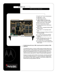
Wireless-G Cable
Gateway
Use this guide to install the following product:
WCG200-CC
User Guide
COPYRIGHT & TRADEMARKS
Specifications are subject to change without notice. Linksys is a registered trademark or
trademark of Cisco Systems, Inc. and/or its affiliates in the U.S. and certain other countries. Copyright © 2003 Cisco Systems, Inc. All rights reserved. Other brands and product names are trademarks or registered trademarks of their respective holders.
FCC STATEMENT
This Wireless-G Cable Gateway has been tested and complies with the specifications for
a Class B digital device, pursuant to Part 15 of the FCC Rules. These limits are designed
to provide reasonable protection against harmful interference in a residential installation.
This equipment generates, uses, and can radiate radio frequency energy and, if not
installed and used according to the instructions, may cause harmful interference to radio
communications. However, there is no guarantee that interference will not occur in a particular installation. If this equipment does cause harmful interference to radio or television
reception, which is found by turning the equipment off and on, the user is encouraged to
try to correct the interference by one or more of the following measures:
•
•
•
•
Reorient or relocate the receiving antenna
Increase the separation between the equipment or device
Connect the equipment to an outlet other than the receiver’s
Consult a dealer or an experienced radio/TV technician for assistance
This device complies with Part 15 of the FCC Rules. Operation is subject to the following two conditions:
•
•
This device may not cause harmful interference.
This device must accept any interference received, including interference that may
cause undesired operation.
SAFETY NOTICES
• Caution: To reduce the risk of fire, use only No.26 AWG or larger telecommunication
line cord.
•
•
Do not use this product near water, for example, in a wet basement or near a swimming pool.
Avoid using this product (other than a cordless type) during an electrical storm.
There may be a remote risk of electric shock from lightning.
WCG200-CC-UG-30904NC-BW
Table of Contents
Chapter 1: Introduction
The Wireless-G Cable Gateway
An Introduction to LANs and WANs
IP Addresses
Network Setup Overview
1
1
2
2
4
Chapter 2: Getting to Know the Cable Gateway
The Cable Gateway’s Back Panel Ports
The Reset Button
Rebooting the Cable Gateway
The USB Icon
USB Cabling
The Cable Gateway’s Front Panel LEDs
5
5
6
6
7
7
8
Chapter 3: Connecting the Cable Gateway
Overview
Ethernet Port Connection
USB Port Connection
Installing the USB Driver for Windows 98
Installing the USB Driver for Windows Millenium
Installing the USB Driver for Windows 2000
Installing the USB Driver for Windows XP
Chapter 4: Configuring the PCs
Overview
Windows 98 and Me
Windows 2000
Windows XP
9
9
9
11
12
15
17
20
22
22
22
24
26
Chapter 1: Introduction
Appendix A: Troubleshooting
Common Problems and Solutions
Frequently Asked Questions
28
28
29
Appendix E: Glossary
33
Appendix F: Specifications
Environmental
41
42
The Wireless-G Cable Gateway
Congratulations on the purchase of your Wireless-G Cable Gateway. This allin-one device has a built-in cable modem, router, and switch, which will enable
you to get connected to your high-speed Internet service through its USB,
wired, or wireless connections.
Let’s take a look at what each function can help you do:
•
The Cable Modem connects you to your the high-speed Internet connection.
•
Connect your computer to the Cable Gateway via USB, or use the built-in
4-port 10/100 Ethernet Switch and share files, printers, and play head-tohead games. Connect four PCs directly, or connect to more hubs and
switches to create as big a network as you need.
•
The Wireless capability allows you to connect PCs, game consoles, and
other devices to your home network without running cables through the
house.
•
The Cable Gateway's Router function ties it all together and lets your
whole network share one high-speed Internet connection. You can share
Internet access with up to five computers.
•
The Cable Gateway has an advanced firewall to help protect your data and
privacy by keeping Internet intruders and attackers out. Wireless transmissions can be protected by powerful data encryption.
1
An Introduction to LANs and WANs
Simply put, a router is a network device that connects two networks together.
The Cable Gateway has a built-in router that connects your Local Area
Network (LAN), which is the group of PCs in your home or office, to the
Wide Area Network (WAN), which is the Internet. The Cable Gateway
processes and regulates the data that travels between these two networks.
Think of the Cable Gateway as a network device with two sides: the first side is
made up of your private Local Area Network (LAN) of PCs. The other, public
side, is the Internet, or the Wide Area Network (WAN), outside of your home or
office.
The Cable Gateway’s firewall protects your network of PCs so users on the public, Internet side cannot “see” your PCs. This is how your local network
remains private. The Cable Gateway protects your network by inspecting the
first packet coming in through the WAN port before delivery to the final destination in the local network. The Cable Gateway inspects Internet port services
like the web server, ftp server, or other Internet applications, and, if allowed,
will forward the packet to the appropriate PC on the LAN side.
Dynamic IP Addresses
A dynamic IP address is automatically assigned to a device on the network,
such as PCs and print servers. These IP addresses are called “dynamic”
because they are only temporarily assigned to the PC or device. After a certain
time period, they expire and may change. If a PC logs onto the network (or the
Internet) and its dynamic IP address has expired, the DHCP server will assign
it a new dynamic IP address.
DHCP (Dynamic Host Configuration Protocol) Servers
DHCP frees you from having to assign IP addresses manually every time a new
user is added to your network. PCs and other network devices using dynamic
IP addressing are assigned a new IP address by a DHCP server. The PC or network device obtaining an IP address is called the DHCP client. By default, the
Cable Gateway’s WAN setting is DHCP client.
A DHCP server can either be a designated PC on the network or another network device, such as the Cable Gateway. By default, the Cable Gateway acts as
a DHCP server for your local network. If you already have a DHCP server running on your network, you must disable that DHCP server or the Cable
Gateway’s DHCP’s feature. If you run more than one DHCP server on your
network, you will experience network errors, such as conflicting IP addresses.
IP Addresses
What’s an IP Address?
IP stands for Internet Protocol. Every device on an IP-based network, including
PCs, print servers, and routers, requires an IP address to identify its “location,”
or address, on the network. This applies to both the WAN and LAN connections.
There are two ways of assigning an IP address to your network devices.
2
Note: Since the Cable Gateway is a device that connects two networks, it
needs two IP addresses—one for the LAN side, and one for the WAN side.
In this User Guide, you’ll see references to the “WAN IP address” and the
“LAN IP address.”
Since the Cable Gateway has firewall security, the only IP address on your
network that can be seen from the Internet is the Cable Gateway’s WAN IP
address.
3
Chapter 2: Getting to Know the
Cable Gateway
Network Setup Overview
This user guide covers information about your home network.
• Chapter 2: Getting to Know the Cable Gateway
This chapter instructs you on the Cable Gateway’s ports, connections, LEDs,
and buttons.
The Cable Gateway’s Back Panel Ports
The Cable Gateway’s ports are located on the back panel of the Cable Gateway,
as shown in Figure 2-1.
• Chapter 3: Connecting the CableGateway
This chapter instructs you on how to connect the Cable line to the Gateway
and connect the PC(s) to the Cable Gateway.
• Chapter 4: Configuring the PCs
This chapter instructs you on how to configure your PC(s) for a DHCP connection, if the network settings are not already set to DHCP.
Even though a technician probably established your initial connection, you may
need the information provided in this user guide for reference or troubleshooting. After the PC(s) are configured to access the Internet through the Gateway,
you can alter the Gateway’s settings further (refer to the Comcast Home
Networking Getting Started Guide.) For example, you can adjust security features and other settings to enable online gaming, run Internet servers, configure a wireless LAN, and more.
Notebook with
Wireless Adapter
WAN
Figure 2-1
On/Off Switch
This switch is used for turning the Cable Gateway
on and off.
Power
The Power port is where the power adapter is connected.
Reset
Press this button if you need to restore the Cable
Gateway to its factory default settings.
USB
This is where you can use a USB cable to connect
to the Cable Gateway.
Ports 1-4
These four ports are where network devices, such as
PCs, print servers, and remote hard drives are connected to your local area network (LAN).
Cable
The Cable port is where the coaxial Cable line is
connected.
LAN
PC with
Ethernet Adapter
Wireless-G
Cable Gateway
Figure 1-1
4
5
The Reset Button
The USB Icon
The USB icon, shown in Figure 2-3, marks a USB port on a PC or device.
Pressing the Reset Button and holding it in for a few seconds will clear all of
the Cable Gateway’s data and restore the factory defaults. This should be done
only if you are experiencing networking problems and have exhausted all of
the other troubleshooting options. By resetting the Cable Gateway, you run the
risk of creating conflicts between your PCs’ actual IP Addresses and what the
Cable Gateway thinks the IP Addresses of the PCs should be. You may be
forced to reboot each network PC.
Figure 2-2
USB Cabling
Rebooting the Cable Gateway
You should only reboot the Cable Gateway after all other troubleshooting
methods have been exhausted. There are two ways to reboot the Cable
Gateway:
1) Turn the Cable Gateway’s power off for a few seconds and power it back on
again.
2) Unplug the Cable Gateway’s power adapter and plug it back in again.
The Cable Gateway comes with one USB cable. One end of the USB cable is
connected to the Cable Gateway and the other end is connected to a computer’s
USB port.
The picture shows two USB ports as they might appear on
your computer. Note the two USB icons marking the
ports.
Figure 2-3
Rebooting the Cable Gateway may cause conflicts with IP Addresses.
6
7
The Cable Gateway’s Front Panel LEDs
Chapter 3: Connecting the Cable
Gateway
Overview
Figure 2-4
Power
Green or red. The Green Power LED is solid when the
Cable Gateway is powered on. If the LED lights up red,
there is an error.
Internet - Cable
Green. The Green LED will go through a series of
flashes as the Cable Gateway goes through its startup
and registration process. It will remain solid when
registration is complete and the Cable Gateway is
operational.
With the Cable Gateway, you can use a standard Ethernet connection or connect via USB. To connect via an Ethernet connection continue with the
Ethernet Cable Connection section. To connect via a USB connection, go to the
next section, USB Cable Connection.
Ethernet Port Connection
Internet -Activity
Green. This LED flashes when data is being sent or
received through the cable Gateway interface.
Ethernet-1-4
Green or red. Ethernet 1-4 LED serves multiple purposes. If the LED is solid green, the Cable Gateway is
successfully connected to a device through the corresponding port (1, 2, 3, or 4). If the LED is flashing
green, the Cable Gateway is actively sending or receiving data over that port. If the LED lights up red, there
is a collision.
USB
Green or red. The LED is solid green when a PC is
connected to the Cable Gateway via USB, and drivers
are installed. If the LED flashes red, the cable is connected, but the driver isn’t loaded.
Wireless
Green or red. The LED flashes green during wireless
activity. If the LED flashes red, there is an error condition.
Proceed to “Chapter 3: Connecting the Cable Gateway.”
8
First, make sure that all the devices that you’ll be working with are powered
down, including your PCs and the Cable Gateway.
Figure 3-1
1. Connect the coaxial
cable that is provided
by Comcast to the
Cable port that is on
the back of the Cable
Gateway, as shown in
Figure 3-1.
2. Connect one end of
Figure 3-2
an Ethernet cable to
your PC’s Ethernet adapter, as shown in Figure 3-2.
Note: If your PC’s Ethernet adapter is not set up, please refer to your Ethernet
adapter’s user guide for more information.
9
3. Connect the other end of the cable to one of the LAN ports on the back of the
Cable Gateway, as shown in Figure 3-3.
USB Port Connection
First, make sure that all the devices that you’ll be working with are powered
down, including your PCs and the Cable Gateway.
Figure 3-3
Make sure there is an Ethernet cable connected from the Cable Gateway to
every PC that you want on your local network. If you are connecting more
than four PCs to the Cable Gateway via Ethernet, you will also need to connect a hub or switch to the Cable Gateway.
Figure 3-4
1. Connect the coaxial cable that is provided by Comcast to the Cable port that
is on the back of the Cable Gateway, as shown in Figure 3-4.
4. Connect the power adapter to the Cable Gateway,
as shown in Figure 3-4. Plug the other end of the
power adapter into the electrical outlet, preferably
a surge protector.
2. Connect one end of a USB cable to your PC’s USB port and connect the other
end of the USB cable to the USB port on the back of the Cable Gateway, as
shown in Figure 3-4.
5. Turn on the Cable Gateway.
3. Connect the power adapter to the Cable Gateway, as
shown in Figure 3-5. Plug the other end of the power
adapter into the electrical outlet, preferably a surge protector.
Figure 3-4
6. Contact Comcast to activate your account. They will need what is called a
MAC Address for the cable modem capability of your Cable Gateway in
order to set up your account. The 12-digit modem MAC address is printed
on a bar code label on the bottom of the Cable Gateway. Once you have
given them this number, Comcast should be able to activate your account.
7. Then, turn on the first PC that you want to use to configure the Cable
Gateway.
Important: Make sure to contact Comcast with your
MAC Address to activate your account.
Go to “Chapter 4: Configuring the PCs.”
4. Turn on the Cable Gateway. Then, turn on your PC.
Figure 3-5
5. During the boot up process, your computer should recognize the device and
ask for driver installation.
6. Next, you will need to install the USB Driver. Continue to the USB Driver
section for your PC’s operating system. Make sure to return to step 7 in this
section after you install the driver.
7. Contact Comcast to activate your account. They will need what is called a
MAC Address for the cable modem capability of your Cable Gateway in
order to set up your account. The 12-digit MAC address is printed on a bar
code label on the bottom of the Cable Gateway. Once you have given them
this number, Comcast should be able to activate your account.
Important: Make sure to contact Comcast with your
MAC Address to activate your account.
Go to “Chapter 4: Configuring the PCs.”
10
11
Installing the USB Driver for Windows 98
3. Select CD-ROM drive as the only location where Windows will search
for the driver software and click the Next button.
1. When the Add New Hardware Wizard window appears, insert the Setup CD
into your CD-ROM drive and click Next.
Figure 3-3
Figure 3-1
2. Select Search for the best driver for your device and click the Next button.
Figure 3-2
12
4. Windows will notify you that it has identified the appropriate driver and is
ready to install it. Click the Next button.
Figure 3-4
13
5. Windows will begin installing the driver for the modem. At this point, the
installation may require files from your Windows 98 CD-ROM. If prompted, insert your Windows 98 CD-ROM into your CD-ROM drive and enter
d:\win98 in the box that appears (where “d” is the letter of your CD-ROM
drive). If you were not supplied with a Windows 98 CD-ROM, your
Windows files may have been placed on your hard drive by your computer
manufacturer. While the location of these files may vary, many manufacturers use c:\windows\options\cabs as the path. Try entering this path into
the box. If no files are found, check your computer’s documentation or contact your computer manufacturer for more information.
6. After Windows has completed installing this driver, click Finish.
Installing the USB Driver for Windows Millennium
1. Start up your PC in Windows Millennium. Windows will detect new hardware connected to your PC.
Figure 3-6
2. Insert the Setup CD into your CD-ROM drive. When Windows asks you
for the location of the best driver, select Automatic search for a better
driver (Recommended) and click the Next button.
Figure 3-5
7. When asked if you want to restart your PC, remove all diskettes and CDROMs from the PC and click Yes. If Windows does not ask you to restart
your PC, click the Start button, choose Shut Down, choose Restart, then
click Yes.
The Windows 98 driver installation is complete. Return to step 7 of the
USB Port Connection section to activate your account and complete the
setup process.
14
Figure 3-7
3. Windows will begin installing the driver for the modem. At this point, the
installation may require files from your Windows Millennium CD-ROM. If
prompted, insert your Windows Millennium CD-ROM into your CD-ROM
drive and enter d:\win9x in the box that appears (where “d” is the letter of
your CD-ROM drive). If you were not supplied with a Windows CD-ROM,
your Windows files may have been placed on your hard drive by your computer manufacturer. While the location of these files may vary,
15
many manufacturers use c:\windows\options\install as the path. Try
entering this path into the box. If no files are found, check your computer’s documentation or contact your computer manufacturer for more information.
Installing the USB Driver for Windows 2000
1. Start up your PC. Windows will notify you that it has detected new hardware. Insert the Setup CD into the CD-ROM drive.
4. When Windows finishes installing the driver, click Finish.
Figure 3-10
2. When the Found New Hardware Wizard screen appears to confirm that
the USB Modem has been identified by your PC, make sure the Setup CD
is in the CD-ROM drive and click Next.
Figure 3-8
5. When asked if you want to restart your PC, remove all diskettes and CDROMs from the PC and click Yes. If Windows does not ask you to restart
your PC, click the Start button, choose Shut Down, choose Restart, then
click Yes.
Figure 3-11
Figure 3-9
The Windows Millennium driver installation is complete. Return to step
7 of the USB Port Connection section to activate your account and complete the setup process.
16
17
3. Select Search for a suitable driver for my device and click the Next button.
5. Windows will notify you that it has located the appropriate driver and is
ready to install it. Click the Next button.
Figure 3-14
Figure 3-12
4. Windows will now search for the driver software. Select only CD-ROM
drives and click the Next button.
6. When Windows has completed installing the driver, click Finish.
Figure 3-15
Figure 3-13
18
The Windows 2000 driver installation is complete. Return to step 7 of
the USB Port Connection section to activate your account and complete
the setup process.
19
Installing the USB Driver for Windows XP
3. Windows will now search for the driver software. Click the Next button.
1. Start up your PC. Windows will notify you that it has detected new hardware. Insert the Setup CD into the CD-ROM drive.
Figure 3-16
2. When the Found New Hardware Wizard screen appears to confirm that the
USB Modem has been identified by your PC, make sure that the Setup CD
is in the CD-ROM drive and click Next.
Figure 3-18
4. When Windows has completed installing the driver, click Finish.
Figure 3-17
Figure 3-19
The Windows XP driver installation is complete. Return to step 7 of the
USB Port Connection section to activate your account and complete the
setup process.
20
21
Chapter 4: Configuring the PCs
Overview
The instructions in this chapter will help you configure each of your computers to be able to communicate with the Cable Gateway.
To do this, you need to configure your PC’s network settings to obtain an IP (or
TCP/IP) address automatically (called DHCP). Computers use IP addresses to
communicate with each other across a local network or the Internet.
You will need to know which operating system your computer is running, such
as Windows 98, Me, 2000, or XP. One way to find out which operating system
you have is by clicking the Start button and selecting the Settings option.
Then, open the Control Panel, and double-click the System icon. The screen
that appears should display your operating system.
2. On the Configuration tab,
select the TCP/IP line for
the applicable Ethernet
adapter, as shown in Figure
4-1. Do not choose a
TCP/IP entry whose name
mentions DUN, PPPoE,
VPN, or AOL. If the word
TCP/IP appears by itself,
select that line. (If there is
no TCP/IP line listed, refer
to “Appendix C: Installing
the TCP/IP Protocol” or
your Ethernet adapter’s
documentation to install
TCP/IP now.) Click the
Properties button.
You may need to configure each computer you are connecting to the Cable
Gateway.
The next few pages show you, step by step, how to configure your network settings based on the type of Windows operating system you are using.
If your operating system is not referenced here, refer to your operating system’s
documentation.
Figure 4-1
3. Click the IP Address
tab. Select Obtain an
IP address automatically, as shown in
Figure 4-2.
Windows 98 and Me
1. Go to the Network screen. Do this by clicking the Start button, selecting
Settings and opening the Control Panel. From there, double-click the
Network icon.
Figure 4-2
22
23
4. Now click the Gateway tab to ensure that the Installed Gateway field is left
blank. Click the OK button.
4. Select Internet Protocol (TCP/IP), as shown in Figure 4-4, and click the
Properties button.
5. Click the OK button again. Windows may ask you for the original
Windows installation disk or additional files. Supply them by pointing to
the
correct
file
location,
e.g.,
D:\win98,
D:\win9x,
c:\windows\options\cabs, etc. (if “D” is the letter of your CD-ROM drive).
6. Windows may ask you to restart your PC. Click the Yes button. If Windows
does not ask you to restart, restart your computer anyway.
Windows 2000
1. Go to the Network screen by clicking the Start button. Click Settings and
then Control Panel. From there, double-click the Network and Dial-up
Connections icon.
2. Select the Local Area Connection icon for the applicable Ethernet adapter
(usually it is the first Local Area Connection listed). Do not choose a
TCP/IP entry whose name mentions DUN, PPPoE, VPN, or AOL. Doubleclick the Local Area Connection.
Figure 4-4
5. Select Obtain an IP address automatically, as shown in Figure 4-5. Once
the new window appears, click the OK button. Click the OK button again
to complete the PC configuration.
3. The Local Area
Connection
Status screen will
appear, as shown
in Figure 4-3.
Click
the
Properties button.
Figure 4-5
6. Restart your computer.
Figure 4-3
24
25
Windows XP
4. Select Internet Protocol (TCP/IP), and click the Properties button.
The following instructions assume you are running Windows XP with the
default interface. If you are using the Classic interface (where the icons and
menus look like previous Windows versions), please follow the instructions for
Windows 2000.
1. Open the Network screen. To do this, click the Start button and select the
Control Panel. From there, click the Network and Internet Connections
icon, followed by the Network Connections icon.
2. Select the Local Area Connection icon for the applicable Ethernet adapter
(usually it is the first Local Area Connection listed). Double-click the
Local Area Connection and click the Properties button.
Figure 4-7
5. Select Obtain an IP address automatically. Once the new window
appears, click the OK button. Click the OK button again (or the Close button if any settings were changed) to complete the PC configuration.
Figure 4-8
Figure 4-6
3. The Local Area Connection Status screen will appear. Click the Properties
button.
26
6. Restart your computer.
27
Appendix A: Troubleshooting
Common Problems and Solutions
This section provides possible solutions to problems regarding the Cable
Gateway’s installation and operation. If your situation is described here, the
problem should be solved by applying the corresponding solution. For more
information, refer to the Comcast Home Networking page at
http://www.homenetworking.comcast.net.
1. The Cable Gateway is not working.
• Verify that the Power cord and other network cables are plugged in.
• Check the Ethernet and Cable LEDs on the Cable Gateway’s front and
verify that they are lit appropriately.
• Verify that Comcast has been given the correct MAC Address for the
cable modem function.
2. I can’t connect to the Cable Gateway.
• Verify that the Cable Gateway is properly installed; LAN connections are
OK, and it is powered ON.
• Make sure that your PC and the Cable Gateway are on the same network
segment. If you are not sure, initiate the DHCP function, and let the PC
get the IP address automatically.
• Make sure that your PC is using an IP address within the default range of
192.168.0.2 to 192.168.0.254 and thus compatible with the Cable
Gateway default IP Address of 192.168.0.1
• Also, the Subnet Mask should be set to 255.255.255.0 to match the Cable
Gateway. For the Cable Gateway, you can check these settings by using
Control Panel-Network to check the Properties for the TCP/IP protocol.
3. The Cable LED will not go solid.
• Verify that the coaxial cable is firmly plugged into the Cable Gateway’s
cable port, with the other end plugged directly into the Cable wall jack.
• Verify that your Cable account is active.
• Verify that Comcast has been given the correct MAC Address for the
cable modem function.
28
4. I can’t access the Internet from the Cable Gateway.
• Check if both ends of the network cable and power adapter are properly
connected. Check if the status LEDs on the front panel are functioning
properly.
• If using Windows 98 or Me, check the TCP/IP setup on the client side.
Run winipcfg by clicking on the Start button, selecting Run, and typing
winipcfg in the Run field. Press Enter. The PC should have an IP address
of 192.168.0.xxx (“xxx” is from 2 to 254.). The Subnet Mask is
255.255.255.0; the default gateway IP should be the Cable Gateway’s IP
Address, and check that the DNS is correct.
• Check the same setup values on the Comcast Cable Gateway’s
Summary/Network page on the web-based user interface.
5. When I enter a URL or IP address, I get a time out error.
• Check to see if your other PCs work. If they do, verify that your PC’s IP
settings are correct (IP address, Subnet Mask, Default Gateway, and
DNS)
• If the PCs are configured correctly, but still not working, check the Cable
Gateway. Make sure that it is connected and ON. Connect to it and check
its settings. (If you cannot connect to it, check the LAN and power connections.)
• If the Cable Gateway is configured correctly, check your Internet connection to see that it is working correctly.
• Manually configure the TCP/IP with a DNS address provided by
Comcast.
Frequently Asked Questions
What is the maximum number of IP addresses that the Cable Gateway will support? Comcast Home Networking supports up to five IP addresses.
Does the Cable Gateway support IPSec Pass-Through? Yes, it is a feature built
into the Cable Gateway.
Does the Cable Gateway support IPX or AppleTalk? No. TCP/IP is the only protocol standard for the Internet and has become the global standard for communications. IPX, a NetWare communications protocol used only to route messages from one node to another, and AppleTalk, a communications protocol
used on Apple and Macintosh networks, can be used for LAN to LAN connections, but those protocols cannot connect from WAN to LAN.
29
What is Network Address Translation and what is it used for? Network Address
Translation (NAT) translates multiple IP addresses on the private LAN to one
public address that is sent out to the Internet. This adds a level of security
since the address of a PC connected to the private LAN is never transmitted
on the Internet. Furthermore, NAT allows the Cable Gateway to be used with
low cost Internet accounts, when only one TCP/IP address is provided by the
ISP. The user may have many private addresses behind this single address
provided by the ISP.
With which type of firewall is the Cable Gateway equipped? The Cable Gateway
uses NAT and TCP/IP port inspections. It also has SPI (Stateful Packet
Inspection).
Does the Cable Gateway support ICQ send file? Yes, with the following fix: click
ICQ menu -> preference -> connections tab->, and check I am behind a
firewall or proxy. Then set the firewall time-out to 80 seconds in the firewall
setting. The Internet user can then send a file to a user behind the Cable
Gateway.
What is DMZ? Demilitarized Zone (DMZ) allows one IP address (computer) to
be exposed to the Internet. Some applications require multiple TCP/IP ports
to be open. It is recommended that you set your computer with a static IP if
you want to use DMZ.
Can multiple gamers on the LAN get on one game server and play simultaneously
with just one public IP address? It depends on which network game or what
kind of game server you are using. For example, Unreal Tournament supports
multi-login with one public IP.
How do I get Half-Life: Team Fortress to work with the Cable Gateway? The default
client port for Half-Life is 27005. The computers on your LAN need to have
“+clientport 2700x” added to the HL shortcut command line; the x would be
6, 7, 8, and on up. This lets multiple computers connect to the same server.
One problem: Version 1.0.1.6 won’t let multiple computers with the same CD
key connect at the same time, even if on the same LAN (not a problem with
1.0.1.3). As far as hosting games, the HL server does not need to be in the
DMZ. Just forward port 27015 to the local IP address of the server computer.
The web page hangs; downloads are corrupt, or nothing but junk characters are
being displayed on the screen. What do I need to do? Force your Ethernet
adapter to 10Mbps or half duplex mode, and turn off the “Auto-negotiate”
feature of your Ethernet adapter as a temporary measure. (Please look at the
Network Control Panel in your Ethernet adapter’s Advanced Properties tab.)
Make sure that your proxy setting is disabled in the browser. Check
http://www.homenetworking.comcast.net for more information.
If all else fails in the installation, what can I do? Reset the Cable Gateway by
holding down the reset button for one second.
30
I am not able to access the Cable Gateway’s web configuration screen. What can
I do? You may have to remove the proxy settings on your Internet browser,
e.g., Netscape Navigator or Internet Explorer. Or remove the dial-up settings
on your browser. Check with your browser documentation.
If DMZ is used, does the exposed user share the public IP with the Cable Gateway?
No.
Does the Cable Gateway pass PPTP packets or actively route PPTP sessions? The
Cable Gateway allows PPTP packets to pass through.
Is the Cable Gateway cross-platform compatible? Any platform that supports
Ethernet and TCP/IP is compatible with the Cable Gateway.
How many ports can be simultaneously forwarded? Theoretically, the Cable
Gateway can establish 520 sessions at the same time, but you can only forward 10 ranges of ports.
Does the Cable Gateway replace a modem? Is there a cable modem in the Cable
Gateway? Yes. The Cable Gateway has an integrated cable modem, so this
product will replace your current cable modem.
How do I get mIRC to work with the Cable Gateway? Set port forwarding to 113
for the computer on which you are using mIRC. If you are experiencing difficulty after setting the port forwarding, try changing the Direct Client-toClient (DCC) settings to a range from 1024 to 1030 on the DCC option and
Forwarding page of the Web-based Setup Utility.
If your questions are not addressed here, refer to the Comcast Home
Networking page online at http://www.homenetworking.comcast.net.
31
Appendix B: Glossary
10BaseT - An Ethernet standard that uses twisted wire pairs.
100BaseTX - IEEE physical layer specification for 100 Mbps over two pairs of
Category 5 UTP or STP wire.
802.11b - One of the IEEE standards for wireless networking hardware.
Products that adhere to a specific IEEE standard will work with each other,
even if they are manufactured by different companies. The 802.11b standard
specifies a maximum data transfer rate of 11Mbps, an operating frequency of
2.4GHz, and WEP encryption for security. 802.11b networks are also referred
to as Wi-Fi networks.
802.11g - A wireless networking standard that specifies a maximum data transfer rate of 54Mbps using OFDM modulation, an operating frequency of
2.4GHz, backward compatibility with IEEE 802.11b devices, and WEP
encryption for security.
Adapter - Printed circuit board that plugs into a PC to add to capabilities or
connectivity to a PC. In a networked environment, a network interface card
(NIC) is the typical adapter that allows the PC or server to connect to the
intranet and/or Internet.
Auto-negotiate - To automatically determine the correct settings. The term is
often used with communications and networking. For example, Ethernet
10/100 cards, hubs and switches can determine the highest speed of the node
they are connected to and adjust their transmission rate accordingly.
Bit - A binary digit. The value - 0 or 1-used in the binary numbering system.
Also, the smallest form of data.
Boot - To cause the computer to start executing instructions. Personal computers contain built-in instructions in a ROM chip that are automatically executed
on startup. These instructions search for the operating system, load it and pass
control to it.
32
Broadband - A data-transmission scheme in which multiple signals share the
bandwidth of a medium. This allows the transmission of voice, data and video
signals over a single medium. Cable television uses broadband techniques to
deliver dozens of channels over one cable.
Browser - A browser is an application program that provides a way to look at
and interact with all the information on the World Wide Web or PC. The word
"browser" seems to have originated prior to the Web as a generic term for user
interfaces that let you browse text files online.
Buffer - A buffer is a shared or assigned memory area used by hardware
devices or program processes that operate at different speeds or with different
sets of priorities. The buffer allows each device or process to operate without
being held up by the other. In order for a buffer to be effective, the size of the
buffer and the algorithms for moving data into and out of the buffer need to be
considered by the buffer designer. Like a cache, a buffer is a "midpoint holding
place" but exists not so much to accelerate the speed of an activity as to support the coordination of separate activities.
Cable Modem - A device that connects a computer to the cable television network, which in turn connects to the Internet. Once connected, cable modem
users have a continuous connection to the Internet. Cable modems feature
asymmetric transfer rates: around 36 Mbps downstream (from the Internet to
the computer), and from 200 Kbps to 2 Mbps upstream (from the computer to
the Internet).
Category 5 - ANSI/EIA (American National Standards Institute/Electronic
Industries Association) Standard 568 is one of several standards that specify
"categories" (the singular is commonly referred to as "CAT") of twisted pair
cabling systems (wires, junctions, and connectors) in terms of the data rates
that they can sustain. CAT 5 cable has a maximum throughput of 100 Mbps and
is usually utilized for 100BaseTX networks.
Default Gateway - The routing device used to forward all traffic that is not
addressed to a station within the local subnet.
DHCP (Dynamic Host Configuration Protocol) - A protocol that lets network
administrators manage centrally and automate the assignment of Internet
Protocol (IP) addresses in an organization's network. Using the Internet's set of
protocol (TCP/IP), each machine that can connect to the Internet needs a
unique IP address. When an organization sets up its computer users with a connection to the Internet, an IP address must be assigned to each machine.
33
Without DHCP, the IP address must be entered manually at each computer and,
if computers move to another location in another part of the network, a new IP
address must be entered. DHCP lets a network administrator supervise and distribute IP addresses from a central point and automatically sends a new IP
address when a computer is plugged into a different place in the network.
DHCP uses the concept of a "lease" or amount of time that a given IP address
will be valid for a computer. The lease time can vary depending on how long a
user is likely to require the Internet connection at a particular location. It's
especially useful in education and other environments where users change frequently. Using very short leases, DHCP can dynamically reconfigure networks
in which there are more computers than there are available IP addresses.
DHCP supports static addresses for computers containing Web servers that
need a permanent IP address.
Unlike e-mail programs in which graphics and program files have to be
"attached," FTP is designed to handle binary files directly and does not add the
overhead of encoding and decoding the data.
Full Duplex - The ability of a device or line to transmit data simultaneously in
both directions.
Gateway - A device that interconnects networks with different, incompatible
communications protocols.
Dynamic IP Address - An IP address that is automatically assigned to a client
station in a TCP/IP network, typically by a DHCP server. Network devices that
serve multiple users, such as servers and printers, are usually assigned static IP
addresses.
Half Duplex - Data transmission that can occur in two directions over a single
line, but only one direction at a time.
Ethernet - IEEE standard network protocol that specifies how data is placed
on and retrieved from a common transmission medium. Has a transfer rate of
10 Mbps. Forms the underlying transport vehicle used by several upper-level
protocols, including TCP/IP and XNS.
Hardware - Hardware is the physical aspect of computers, telecommunications, and other information technology devices. The term arose as a way to distinguish the "box" and the electronic circuitry and components of a computer
from the program you put in it to make it do things. The program came to be
known as the software.
Firewall - A firewall is a set of related programs, located at a network gateway
server, that protects the resources of a network from users from other networks.
(The term also implies the security policy that is used with the programs.) An
enterprise with an intranet that allows its workers access to the wider Internet
installs a firewall to prevent outsiders from accessing its own private data
resources and for controlling what outside resources to which its own users
have access.
Basically, a firewall, working closely with a router, examines each network
packet to determine whether to forward it toward its destination.
FTP (File Transfer Protocol) - A protocol used to transfer files over a TCP/IP
network (Internet, UNIX, etc.). For example, after developing the HTML pages
for a Web site on a local machine, they are typically uploaded to the Web server using FTP.
34
FTP includes functions to log onto the network, list directories and copy files.
It can also convert between the ASCII and EBCDIC character codes. FTP operations can be performed by typing commands at a command prompt or via an
FTP utility running under a graphical interface such as Windows. FTP transfers
can also be initiated from within a Web browser by entering the URL preceded
with ftp://.
IP (Internet Protocol) - The method or protocol by which data is sent from one
computer to another on the Internet. It is a standard set of rules, procedures, or
conventions relating to the format and timing of data transmission between two
computers that they must accept and use to be able to understand each other.
IP Address - In the most widely installed level of the Internet Protocol (IP)
today, an IP address is a 32-binary digit number that identifies each sender or
receiver of information that is sent in packet across the Internet. When you
request an HTML page or send e-mail, the Internet Protocol part of TCP/IP
includes your IP address in the message (actually, in each of the packets if more
than one is required) and sends it to the IP address that is obtained by looking
up the domain name in the Uniform Resource Locator you requested or in the
e-mail address you're sending a note to. At the other end, the recipient can see
the IP address of the Web page requestor or the e-mail sender and can respond
by sending another message using the IP address it received.
35
ISP (Internet Service Provider) - A company that provides individuals and
companies access to the Internet and other related services such as Web site
building and virtual hosting.
LAN (local area network) - A group of computers and associated devices that
share a common communications line and typically share the resources of a
single processor or server within a small geographic area (for example, within
an office building).
Mbps (Megabits per second) - One million bits per second; unit of measurement for data transmission.
Network - A system that transmits any combination of voice, video and/or data
between users.
NIC (Network Interface Card) - A board installed in a computer system, usually a PC, to provide network communication capabilities to and from that computer system. Also called an adapter.
Notebook (PC) - A notebook computer is a battery-powered personal computer generally smaller than a briefcase that can easily be transported and conveniently used in temporary spaces such as on airplanes, in libraries, temporary
offices, and at meetings. A notebook computer, sometimes called a laptop computer, typically weighs less than five pounds and is three inches or less in thickness.
Packet - A unit of data routed between an origin and a destination in a network.
Packet Filtering - Discarding unwanted network traffic based on its originating address or range of addresses or its type (e-mail, file transfer, etc.).
PC Card - A credit-card sized removable module that contains memory, I/O,
or a hard disk.
Port - A pathway into and out of the computer or a network device such as a
switch or router. For example, the serial and parallel ports on a personal computer are external sockets for plugging in communications lines, modems and
printers.
Router - Protocol-dependent device that connects subnetworks together.
Routers are useful in breaking down a very large network into smaller subnetworks; they introduce longer delays and typically have much lower throughput
rates than bridges.
Server - Any computer whose function in a network is to provide user access
to files, printing, communications, and other services.
Software - Instructions for the computer. A series of instructions that performs
a particular task is called a "program." The two major categories of software are
"system software" and "application software." System software is made up of
control programs such as the operating system and database management system (DBMS). Application software is any program that processes data for the
user.
A common misconception is that software is data. It is not. Software tells the
hardware how to process the data.
SPI (Stateful Packet Inspection) - A firewall technology that monitors the state
of the transaction so that it can verify that the destination of an inbound packet matches the source of a previous outbound request. It examines not just the
headers of the packet, but also the contents, to determine more about the packet than just its source and destination information. It is called "stateful" because
verifies that the stated destination computer has previously requested the current communication. In this way, it verifies that all communications are initiated by the recipient computer and are taking place only with sources that are
known and trusted from previous interactions. In addition to being a more rigorous inspection, stateful packet inspection closes off ports until connection to
the specific port is requested. This allows an added layer of protection from the
threat of port scanning.
SSID (Service Set IDentifier) - A unique name shared among all points in a
wireless network. The SSID must be identical for each point in the wireless network and is case-sensitive.
Subnet Mask - The method used for splitting IP networks into a series of subgroups, or subnets. The mask is a binary pattern that is matched up with the IP
address to turn part of the host ID address field into a field for subnets.
RJ-45 (Registered Jack-45) - A connector similar to a telephone connector that
holds up to eight wires, used for connecting Ethernet devices.
36
37
Switch - 1. A data switch connects computing devices to host computers,
allowing a large number of devices to share a limited number of ports. 2. A
device for making, breaking, or changing the connections in an electrical circuit.
USB 1.1-compliant devices support data rates of 1.5Mbps (low speed) and up
to 12Mbps (full speed). USB 2.0-compliant devices are backward compatible
with earlier USB devices, and they support data rates of 1.5Mbps (low speed),
12Mbps (full speed), and up to 480Mbps (high speed).
TCP (Transmission Control Protocol) - A method (protocol) used along with
the IP (Internet Protocol) to send data in the form of message units (datagram)
between network devices over a LAN or WAN. While IP takes care of handling
the actual delivery of the data (routing), TCP takes care of keeping track of the
individual units of data (called packets) that a message is divided into for efficient delivery over the network. TCP is known as a "connection oriented" protocol due to requiring the receiver of a packet to return an acknowledgment of
receipt to the sender of the packet resulting in transmission control.
UTP - Unshielded twisted pair is the most common kind of copper telephone
wiring. Twisted pair is the ordinary copper wire that connects home and many
business computers to the telephone company. To reduce crosstalk or electromagnetic induction between pairs of wires, two insulated copper wires are
twisted around each other. Each signal on twisted pair requires both wires.
Since some telephone sets or desktop locations require multiple connections,
twisted pair is sometimes installed in two or more pairs, all within a single
cable.
TCP/IP (Transmission Control Protocol/Internet Protocol) - The basic communication language or set of protocols for communications over a network
(developed specifically for the Internet). TCP/IP defines a suite or group of
protocols and not only TCP and IP.
WAN (Wide Area Network)- A communications network that covers a relatively large geographic area, consisting of two or more LANs. Broadband communication over the WAN is often through public networks such as the telephone (DSL) or cable systems, or through leased lines or satellites. In its most
basic definition, the Internet could be considered a WAN.
Transmit Channel - The channel or frequency that your wireless network is currently transmitting on. Changes must be made in the Wireless section within the
Feature Setup section.
WINIPCFG - Configuration utility based on the Win32 API for querying,
defining and managing IP addresses within a network. A commonly used utility for configuring networks with static IP addresses.
TX Rate - Transmission Rate.
Upload - To transmit a file over a network. In a communications session,
upload means transmit, download means receive.
URL (Uniform Resource Locator) - The address that defines the route to a file
on the Web or any other Internet facility. URLs are typed into the browser to
access Web pages, and URLs are embedded within the pages themselves to provide the hypertext links to other pages.
USB (Universal Serial Bus) - A "plug-and-play" interface between a computer and peripherals, such as digital cameras, scanners, game controllers, speakers, keyboards, portable data storage, or printers. With USB, you can add a new
peripheral to your computer without having to add an adapter card or powering
down the computer. USB also supports hot-swapping, the addition or removal
of devices while the computer is running.
38
39
Appendix C: Specifications
40
Model Number
WCG200-CC
Standards
DOCSIS 1.0, DOCSIS 1.1, DOCSIS 2.0, IEEE 802.11g,
IEEE 802.11b.
Ports
4 RJ-45 10/100, 1 USB, 1 Female Coax F-Connector
Buttons
Power ON/OFF switch, Reset
Environmental
Dimensions:
7.32" x 2.48" x 6.08" (186 mm x 63 mm x 154.5 mm)
Unit Weight:
1.5 lb. (0.68 kg)
Power:
12VDC, 1A
Certifications:
DOCSIS 1.1, DOCSIS 2.0, FCC Part 15B Class B, UL
1950, EN60950, CE EN 55022 Class B, VCCI, IC-03
Operating Temp.:
0ºC to 40ºC (32ºF to 104ºF)
Cabling Type
Cable
LAN
USB
Coaxial
UTP Category 5 or better
Type B USB
Storage Temp.:
-20°C-70°C (-4°F-158°F)
Operating Humidity:
20% to 90%, Non-Condensing
LEDs
Power, Cable, Activity, Ethernet, USB, Wireless
Storage Humidity:
20% to 90%, Non-Condensing
Security
WEP, MAC address filtering, SPI Firewall
41
www.linksys.com
© Copyright 2003 Linksys, All Rights Reserved.