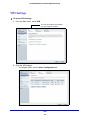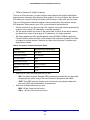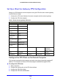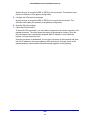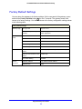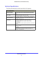
1
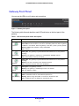
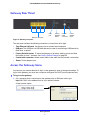
CG3000DCR Advanced Cable Modem Gateway User M anua l 350 East Plumeria Drive San Jose, CA 95134 USA January 2013 202-11231-01 v1.0 CG3000DCR Advanced Cable Modem Gateway Support Thank you for selecting NETGEAR products. After installing your device, locate the serial number on the label of your product and use it to register your product at https://my.netgear.com. You must register your product before you can use NETGEAR telephone support. NETGEAR recommends registering your product through the NETGEAR website. For product updates and web support, visit http://support.netgear.com. Phone (US & Canada only): 1-888-NETGEAR. Phone (Other Countries): Check the list of phone numbers at http://support.netgear.com/general/contact/default.aspx. Trademarks NETGEAR, the NETGEAR logo, and Connect with Innovation are trademarks and/or registered trademarks of NETGEAR, Inc. and/or its subsidiaries in the United States and/or other countries. Information is subject to change without notice. © NETGEAR, Inc. All rights reserved. 2 Contents Chapter 1 Getting Started Gateway Front Panel . . . . . . . . . . . . . . . . . . . . . . . . . . . . . . . . . . . . . . . . . . 6 Gateway Rear Panel . . . . . . . . . . . . . . . . . . . . . . . . . . . . . . . . . . . . . . . . . . 7 Access the Gateway Menu. . . . . . . . . . . . . . . . . . . . . . . . . . . . . . . . . . . . . . 7 View the Gateway Summary Screen . . . . . . . . . . . . . . . . . . . . . . . . . . . . . . 9 Chapter 2 Cusadmin Features Administration. . . . . . . . . . . . . . . . . . . . . . . . . . . . . . . . . . . . . . . . . . . . . . . 11 LAN Setup . . . . . . . . . . . . . . . . . . . . . . . . . . . . . . . . . . . . . . . . . . . . . . . . . 12 Static Routing . . . . . . . . . . . . . . . . . . . . . . . . . . . . . . . . . . . . . . . . . . . . . 13 Filtering. . . . . . . . . . . . . . . . . . . . . . . . . . . . . . . . . . . . . . . . . . . . . . . . . . 14 Switch Port Controls . . . . . . . . . . . . . . . . . . . . . . . . . . . . . . . . . . . . . . . . 15 Firewall Settings . . . . . . . . . . . . . . . . . . . . . . . . . . . . . . . . . . . . . . . . . . . . . 16 Port Configuration. . . . . . . . . . . . . . . . . . . . . . . . . . . . . . . . . . . . . . . . . . 17 Website Blocking . . . . . . . . . . . . . . . . . . . . . . . . . . . . . . . . . . . . . . . . . . 18 Set Up a DMZ Host . . . . . . . . . . . . . . . . . . . . . . . . . . . . . . . . . . . . . . . . 19 Disable NAT . . . . . . . . . . . . . . . . . . . . . . . . . . . . . . . . . . . . . . . . . . . . . . 20 Chapter 3 MSO Access MSO Welcome Screen . . . . . . . . . . . . . . . . . . . . . . . . . . . . . . . . . . . . . . . . 22 Initial Setup. . . . . . . . . . . . . . . . . . . . . . . . . . . . . . . . . . . . . . . . . . . . . . . . . 23 Administration. . . . . . . . . . . . . . . . . . . . . . . . . . . . . . . . . . . . . . . . . . . . . . . 24 WAN IP Setup . . . . . . . . . . . . . . . . . . . . . . . . . . . . . . . . . . . . . . . . . . . . . . 25 RIP Control . . . . . . . . . . . . . . . . . . . . . . . . . . . . . . . . . . . . . . . . . . . . . . . . . 26 Chapter 4 VPN VPN Settings . . . . . . . . . . . . . . . . . . . . . . . . . . . . . . . . . . . . . . . . . . . . . . . 28 VPN Configuration . . . . . . . . . . . . . . . . . . . . . . . . . . . . . . . . . . . . . . . . . . . 29 Client-to-Gateway VPN Tunnels. . . . . . . . . . . . . . . . . . . . . . . . . . . . . . . 29 Gateway-to-Gateway VPN Tunnels . . . . . . . . . . . . . . . . . . . . . . . . . . . . 30 Planning a VPN . . . . . . . . . . . . . . . . . . . . . . . . . . . . . . . . . . . . . . . . . . . . . 30 Set Up a Client-to-Gateway VPN Configuration . . . . . . . . . . . . . . . . . . . . . 32 Configure the VPN Client on the Remote Computer . . . . . . . . . . . . . . . 32 Chapter 5 Troubleshooting Basic Functions . . . . . . . . . . . . . . . . . . . . . . . . . . . . . . . . . . . . . . . . . . . . . 35 Use LEDs to Troubleshoot . . . . . . . . . . . . . . . . . . . . . . . . . . . . . . . . . . . 35 3 CG3000DCR Advanced Cable Modem Gateway Access the Gateway Menu. . . . . . . . . . . . . . . . . . . . . . . . . . . . . . . . . . . . . 36 Troubleshoot the ISP Connection . . . . . . . . . . . . . . . . . . . . . . . . . . . . . . . 36 Troubleshoot a TCP/IP Network Using a Ping Utility . . . . . . . . . . . . . . . . . 37 Test the LAN Path to Your Gateway . . . . . . . . . . . . . . . . . . . . . . . . . . . 37 Test the Path from Your Computer to a Remote Device . . . . . . . . . . . . 38 Appendix A Supplementary Information Factory Default Settings . . . . . . . . . . . . . . . . . . . . . . . . . . . . . . . . . . . . . . . 40 Technical Specifications. . . . . . . . . . . . . . . . . . . . . . . . . . . . . . . . . . . . . . . 41 Appendix B Notification of Compliance 4 1. Getting Started 1 This chapter covers the following topics: • Gateway Front Panel • Gateway Rear Panel • Access the Gateway Menu • View the Gateway Summary Screen Note: Do not mount this unit to a wall; it is not suitable for wall mounting. For more information about the topics covered in this manual, visit the support website at http://support.netgear.com. Firmware updates with new features and bug fixes are made available from time to time on downloadcenter.netgear.com. Some products can regularly check the site and download new firmware, or you can check for and download new firmware manually. If the features or behavior of your product do not match what is described in this guide, you might need to update your firmware. 5 CG3000DCR Advanced Cable Modem Gateway Gateway Front Panel You can use the LEDs to verify status and connections. Figure 1. Gateway front panel The following table lists and describes each LED and button on the front panel of the gateway. Table 1. LED and front panel button descriptions LED Description Power •Solid green. Power is supplied to the gateway. •Solid amber. Power has been cut off due to overheating. Make sure that the gateway ventilation is not blocked. When the gateway cools down, power cycle the gateway. •Blinking amber. New firmware is being downloaded. •Off. No power. Downstream Upstream Internet LAN (Ethernet) •Solid green. The gateway is synchronized and all channels are in use (channel bonding). •Blinking: The gateway is scanning for a downstream DOCSIS channel. •Off: No downstream channels are locked. •Solid green. The gateway is synchronized and all channels are in use (channel bonding). •Blinking: The unit is scanning for an upstream channel. •Off: No upstream channels have been established. •Solid green: The gateway is online. •Blinking: The gateway is establishing its link to the Internet. •Off: The gateway is offline. Green indicates 1,000 Mbps. Amber indicates 100/10 Mbps. •Solid. An Ethernet device is connected and powered on. •Blinking. Data is being transmitted or received on the Ethernet port. •Off. No Ethernet device is detected on the Ethernet port. Getting Started 6 CG3000DCR Advanced Cable Modem Gateway Gateway Rear Panel USB port Ethernet LAN ports Factory Defaults button Coaxial cable connector Power adapter input Figure 2. Gateway rear panel The rear panel includes the following connections, viewed from left to right: • Four Ethernet LAN ports. Use these ports to connect local computers. • USB port. The USB port is a USB host and can be used for connecting a USB hard drive, flash drive, or printer. • Factory Defaults button. To return the gateway to its factory settings, press and hold this button for over 7 seconds. See Factory Default Settings on page 40. • Coaxial cable connector. Attach coaxial cable to the cable service provider’s connection. • Power. Power adapter input. Access the Gateway Menu You can use your Internet browser to log in to the gateway to view or change its settings. To log in to the gateway you must use a computer configured for DHCP (most computers are). To log in to the gateway: 1. On a computer that is connected to the gateway with an Ethernet cable, type http://10.1.10.1 in the address field of your Internet browser. A login window opens. Getting Started 7 CG3000DCR Advanced Cable Modem Gateway The gateway has two user names with passwords, which are case-sensitive: • To access Initial Setup and Feature Settings, log in with the user name MSO and its default password of D0nt4g3tme (the password uses a zero, not the letter O). • To access only the Feature Settings, log in with the user name cusadmin and its default password of highspeed. NETGEAR recommends that you change these to more secure passwords. See Administration on page 11. 2. Enter a user name and password. The cusadmin user Welcome screen displays. Note: If you changed the password and cannot locate it, you can use the Factory Defaults button. See Factory Default Settings on page 40. Getting Started 8 CG3000DCR Advanced Cable Modem Gateway View the Gateway Summary Screen You can use the Gateway Summary screen to see if the gateway initialization is complete and to check its overall status. To view the Gateway Summary screen: From the Main menu, click the Cable Modem tab. The Gateway Summary screen displays. Four tabs are available: Gateway Status, Network, Wireless Security, and Cable Modem. Getting Started 9 2. Cusadmin Features 2 This chapter describes how to use feature settings when logged in with the cusadmin user name. For information about the Gateway Summary screen, see Viewing the Gateway Summary Screen on page 9. This chapter includes: • Administration • LAN Setup • Firewall Settings For information about configuring VPNs, see Chapter 4, VPN. 10 CG3000DCR Advanced Cable Modem Gateway Administration You can use the Administration features to set up passwords and to run diagnostics. To view administration: From the Main menu, select Administration. The cusadmin user name default password is highspeed. You should change this to a more secure password. You can also specify the password idle time, which is the number of minutes the gateway waits to log out a cusadmin user if there is no user activity. Note: If you want to run the ping diagnostic, click the Diagnostic Tools tab. You can also run ping from Windows. See Troubleshooting a TCP/IP Network Using a Ping Utility on page 32. Cusadmin Features 11 CG3000DCR Advanced Cable Modem Gateway LAN Setup You can use the LAN screen to configure IP setup, static routing, filtering, and wwitch controls. To display LAN IP setup: From the Main menu, select LAN. You can use this screen to specify the IP information, set up DHCP, or assign DNS manually. Cusadmin Features 12 CG3000DCR Advanced Cable Modem Gateway Static Routing Static routes provide more routing information to your gateway. Typically, you do not need to add static routes. You have to configure static routes only for unusual cases such as multiple gateways or multiple IP subnets on your network. To create a static route: 1. From the Main menu, select LAN and click the Static Routing tab. 2. Define each static route, select its Active check box. 3. Click apply. Cusadmin Features 13 CG3000DCR Advanced Cable Modem Gateway Filtering By default, the gateway allows any connected computer to access the Internet. The Filtering screen lets you block specific computers, based on their MAC address, from access to the Internet on selected days and times. To use filtering: 1. From the Main menu, select LAN and click the Filtering tab. 2. On the Filtering tab, select the Enable Access Filter check box. 3. Enter the MAC address for each computer that will be allowed to access the Internet. 4. Click apply so that your changes take effect. Cusadmin Features 14 CG3000DCR Advanced Cable Modem Gateway Switch Port Controls To view the Switch Port Controls screen: From the Main menu, select LAN and click the Switch Controls tab. Cusadmin Features 15 CG3000DCR Advanced Cable Modem Gateway Firewall Settings By default the gateway firewall is enabled to provide security to the network. You can configure firewall settings. To change the firewall settings: 1. From the Main menu, select Firewall. 2. Click the tabs to configure port configuration, website blocking, DMZ, and 1-to-1 NAT. Cusadmin Features 16 CG3000DCR Advanced Cable Modem Gateway Port Configuration You can set up port forwarding, port triggering, port blocking, and true static IP port management. To change the port configuration: From the Main menu, select Firewall and click the Port Configuration tab. Port Forwarding A firewall has two default rules, one for inbound traffic (WAN to LAN) and one for outbound traffic. Port forwarding affects the inbound rules. These rules restrict access from outsiders. The default rule is to block all access from outside except responses to requests from the LAN side. You can use port forwarding to add predefined or custom rules to specify exceptions to the default rule. Because the gateway uses Network Address Translation (NAT), your network presents only one IP address to the Internet, and outside users cannot directly address any of your local computers. However, by defining an inbound rule you can make a local server (for example, a web server or game server) or computer visible and available to the Internet. The rule tells the gateway to direct inbound traffic for a particular service to one local server or computer based on the destination port number. This is known as port forwarding. Port Triggering Port triggering is an advanced feature that can be used to easily enable gaming and other Internet applications that the firewall would otherwise block. Using this feature requires that you know the port numbers that the application uses. Cusadmin Features 17 CG3000DCR Advanced Cable Modem Gateway Port Blocking You can use port blocking to block outbound traffic on specific ports. Outbound traffic rules control access to outside resources from local users. The default rule is to allow all access from the LAN side to the outside. You can use port blocking to add predefined or custom rules to specify exceptions to the default rule. Note: Any outbound traffic that is not blocked by rules that you have created is allowed. True Static IP Port Management This feature allows certain inbound traffic to specific computers on the true static IP network. Website Blocking You can set up the gateway to block access to website that you specify. To block websites: 1. From the Main menu, select Firewall and click the Web Site Blocking tab. 2. Select the Enable Web Site Blocking check box. 3. In the New Key Word/URL field, enter the key words and URLs that you want to block. 4. You can also specify which computers are trusted computers. 5. When you are finished, click apply so that your changes take effect. Cusadmin Features 18 CG3000DCR Advanced Cable Modem Gateway Set Up a DMZ Host You can set up a computer to be a DMZ host. The computer that is the DMZ host will be available to anyone on the Internet for services that you have not defined. There are security issues with doing this, so set up the DMZ host only if you are willing to risk open access. If you do not define a DMZ host, the gateway discards any undefined service requests. To set up a DMZ host: From the Main menu, select Firewall and click the DMZ tab. Cusadmin Features 19 CG3000DCR Advanced Cable Modem Gateway Disable NAT When the gateway uses Network Address Translation (NAT), your network presents only one IP address to the Internet, and outside users cannot directly address any of your local computers. To disable NAT: 1. From the Main menu, select Firewall and click the 1-to-1 NAT tab. 2. Select the Disable all check box. 3. Click apply. Cusadmin Features 20 3. MSO Access 3 This chapter describes features that are available only when logged in with the MSO user name. The following sections are included: • MSO Welcome Screen • Initial Setup • Administration • WAN IP Setup • RIP Control For information about VPN, see Chapter 4, VPN. 21 CG3000DCR Advanced Cable Modem Gateway MSO Welcome Screen Log in to the gateway with the MSO user name . See Accessing the Gateway Menu on page 7. When you connect to the gateway the Welcome screen displays. Initial Setup and WAN are available only for MSO users. MSO Access 22 CG3000DCR Advanced Cable Modem Gateway Initial Setup To view or change initial setup: 1. Log in as MSO. 2. From the Main menu, select Initial Setup. 3. Change the following settings as needed: • LAN IP Address. The LAN IP address for the gateway in dotted decimal notation. The factory default setting is 10.1.10.1. • LAN Subnet Mask. The network number portion of an IP address. Unless you are implementing subnetting, use 255.255.255.0 as the subnet mask. • Enable LAN DHCP. The gateway is set up by default as a Dynamic Host Configuration Protocol (DHCP) server, which provides the TCP/IP configuration for all the computers that are connected to the gateway. • Enable DMZ Host. This allows you to set up a computer that is available to anyone on the Internet for services that you have not defined. There are security issues with doing this, so set up the DMZ host only if you are willing to risk open access. If you do not define a DMZ host, the gateway discards any undefined service requests. • Router Name. The name of the gateway. • TFTP Configuration Download. Initiate a download. 4. If you made changes, click apply so that they take effect. Note: You can specify more settings in the WAN screen. See WAN IP Setup on page 25. MSO Access 23 CG3000DCR Advanced Cable Modem Gateway Administration When logged in as MSO, the Administration screen includes more tabs for remote management, logging and reporting, and configuration tools. MSO Access 24 CG3000DCR Advanced Cable Modem Gateway WAN IP Setup To view or change the WAN IP setup: 1. While logged in as MSO, from the Main menu, select WAN. 2. You can click Additional Public Subnets to go to the following screen: 3. When you have made changes, click apply. MSO Access 25 CG3000DCR Advanced Cable Modem Gateway RIP Control To set up RIP Control: While logged in as MSO, from the Main menu, select WAN and click the RIP Control tab. MSO Access 26 4. VPN 4 This chapter describes how to use the virtual private networking (VPN) features of the gateway. VPN communications paths are called tunnels. VPN tunnels provide secure, encrypted communications between your local network and a remote network or computer. The following sections are included: • VPN Settings • VPN Configuration • Planning a VPN • Set Up a Client-to-Gateway VPN Configuration 27 CG3000DCR Advanced Cable Modem Gateway VPN Settings To access VPN settings: 1. From the Main menu, select VPN. The VPN Termination tab is available only when logged in as MSO. 2. Enter the VPN settings. • To configure IpSec, click the IpSec Configuration tab. VPN 28 CG3000DCR Advanced Cable Modem Gateway • To create user accounts for remote PPTP and L2TP VPN access, click the PPTP/L2TP Configuration tab. VPN Configuration Two common scenarios for configuring VPN tunnels are between a remote computer and a network gateway; and between two or more network gateways. The gateway supports both of these types of VPN configurations. The gateway supports up to five concurrent tunnels. Client-to-Gateway VPN Tunnels Client-to-gateway VPN tunnels provide secure access from a remote computer, such as a home user connecting to an office network. VPN tunnel PC running NETGEAR PrSafe VPN client Figure 3. VPN tunnel from a client to a gateway A VPN client access allows a remote computer to connect to your network from any location on the Internet. In this case, the remote computer is one tunnel endpoint, running the VPN VPN 29 CG3000DCR Advanced Cable Modem Gateway client software. The gateway on your network is the other tunnel endpoint. See Set Up a Client-to-Gateway VPN Configuration on page 32 for information about how to set up this configuration. Gateway-to-Gateway VPN Tunnels Gateway-to-gateway VPN tunnels provide secure access between networks, such as a branch or home office and a main office. VPN tunnel Figure 4. VPN tunnel between two gateways A VPN between two or more NETGEAR VPN-enabled routers is a good way to connect branch or home offices and business partners over the Internet. VPN tunnels also enable access to network resources across the Internet. In this case, use gateways on each end of the tunnel to form the VPN tunnel endpoints. Planning a VPN When you set up a VPN, it is helpful to plan the network configuration and record these configuration parameters: • Connection name • Pre-shared key • Secure association (main mode or manual keys) • Perfect Forward Secrecy • Encryption Protocol • Diffie-Hellman (DH) Group • Key life in seconds • IKE life time in seconds • VPN endpoint • Local IPSec ID • LAN IP address • Subnet mask VPN 30 CG3000DCR Advanced Cable Modem Gateway • FQDN or Gateway IP (WAN IP Address) To set up a VPN connection, you must configure each endpoint with specific identification and connection information describing the other endpoint. You must configure the outbound VPN settings on one end to match the inbound VPN settings on other end, and vice versa. This set of configuration information defines a security association (SA) between the two VPN endpoints. When planning your VPN, you must make a few choices first: • Will the local end be any device on the LAN, a portion of the local network (as defined by a subnet or by a range of IP addresses), or a single computer? • Will the remote end be any device on the remote LAN, a portion of the remote network (as defined by a subnet or by a range of IP addresses), or a single computer? • Will either endpoint use fully qualified domain names (FQDNs)? FQDNs supplied by Dynamic DNS providers can allow a VPN endpoint with a dynamic IP address to initiate or respond to a tunnel request. Otherwise, the side using a dynamic IP address must always be the initiator. Table 2. Parameters recommended by the VPNC Parameter Gateway Factory Default Setting Secure Association Main Mode Authentication Method Pre-shared Key Encryption Method 3DES Authentication Protocol SHA-1 Diffie-Hellman (DH) Group Group 2 (1024 bit) Key Life 8 hours IKE Life Time 1 hour • • What level of IPSec VPN encryption will you use? - DES. The Data Encryption Standard (DES) processes input data that is 64 bits wide, encrypting these values using a 56-bit key. Faster but less secure than 3DES. - 3DES. Triple DES achieves a higher level of security by encrypting the data three times using DES with three different, unrelated keys. What level of authentication will you use? - MDS. 128 bits, faster but less secure. - SHA-1. 160 bits, slower but more secure. VPN 31 CG3000DCR Advanced Cable Modem Gateway Set Up a Client-to-Gateway VPN Configuration Setting up a VPN between a remote computer running the VPN client and a network gateway involves these two steps: 1. Configure the VPN tunnel between the remote computer and the network gateway. 2. Configure the VPN client endpoint. Table 3. Sample client-to-gateway VPN tunnel VPN Tunnel Configuration Connection Name RoadWarrior Pre-Shared Key 12345678 Secure Association Main Perfect Forward Secrecy Disabled Encryption Protocol 3DES Authentication Protocol SHA-1 Diffie-Hellman (DH) Group Group 2 Key Life in seconds 28800 (8 hours) IKE Life Time in seconds 3600 (1 hour) VPN Endpoint Local IPSec ID LAN IP Address Subnet Mask FQDN or Gateway IP (WAN IP Address) Client toCG3000D — — Dynamic CG3000DCR toClient 192.168.3.1 255.255.255.0 22.23.24.25 Configure the VPN Client on the Remote Computer This overview assumes that the computer running the client has a dynamically assigned IP address. The computer must have a VPN client program installed that supports IPSec. To configure the VPN client: 1. Add a connection. 2. Configure the security policy in the VPN client software. 3. Configure the VPN client identity. 4. Configure the VPN client authentication. VPN 32 CG3000DCR Advanced Cable Modem Gateway Specify the type of encryption (DES or 3DES) for this connection. This selection must match your selection in the gateway configuration. 5. Configure the VPN client key exchange. Specify the type of encryption (DES or 3DES) to be used for this connection. This selection must match your selection in the gateway configuration. 6. Save the VPN client settings. 7. Check the VPN connection. To check the VPN connection, you can initiate a request from the remote computer to the gateway’s network. The client reports the results of the attempt to connect. Since the remote computer has a dynamically assigned WAN IP address, it must initiate the request. You can use ping for this. Once the connection is established, you can open a browser on the computer and enter the LAN IP address of the remote gateway. After a short wait, the login screen of the gateway displays (unless another computer already logged in to the gateway). VPN 33 5. Troubleshooting 5 This chapter gives information about troubleshooting the gateway. For the common problems listed, go to the section indicated. • Have I connected the gateway correctly? Go to Basic Functions . • I cannot access the gateway configuration with my browser. Go to Access the Gateway Menu . • I have configured the gateway but I cannot access the Internet. Go to Troubleshoot the ISP Connection . • I cannot remember the gateway’s configuration password or I want to clear the configuration and start over again. Go to Factory Default Settings on page 40. Tip: NETGEAR provides helpful articles, documentation, and the latest software updates at http://www.netgear.com/support. 34 CG3000DCR Advanced Cable Modem Gateway Basic Functions After you have turned on power to the gateway, you should do the following: 1. Check to see that the Power LED is lit. 2. Check that the numbered Ethernet LEDs come on momentarily. 3. After a few seconds, check that the local port link LEDs are lit for any local ports that are connected. If any of these conditions does not occur, refer to the appropriate following section. Use LEDs to Troubleshoot The following table provides help when using the LEDs for troubleshooting. Table 4. Using LEDs to troubleshoot LED Behavior Action All LEDS are off when the gateway Make sure that the power cord is properly connected to your gateway is plugged in. and that the power supply adapter is properly connected to a functioning power outlet. Check that you are using the 12VDC power adapter supplied by NETGEAR for this product. If the error persists, you have a hardware problem and should contact technical support. All LEDs stay lit • • LAN LED is off for a port with an Ethernet connection. • • • • Internet LED is off and the gateway is connected with coaxial cable to the cable television jack. • • Clear the gateway’s configuration to factory defaults, which returns gateway’s IP address to 10.10.1. See Factory Default Settings in Appendix A. If the error persists, you might have a hardware problem and should contact technical support. Make sure that the Ethernet cable connections are secure at the gateway and at the hub or computer. Make sure that power is turned on to the connected hub or computer. Be sure you are using the correct cable. Make sure that the coaxial cable connections are secure at the gateway and at the wall jack. Make sure that your cable Internet service has been provisioned by your cable service provider. Your provider should verify that the signal quality is good enough for cable modem service. Remove any excessive splitters that are on the cable line. You might need to run a “home run” back to the point where the cable enters the home. Troubleshooting 35 CG3000DCR Advanced Cable Modem Gateway Access the Gateway Menu If you are unable to access the gateway’s main menu from a computer on your local network, check the following: • Check the Ethernet connection between the computer and the gateway as described in the previous section. • Make sure that your computer’s IP address is on the same subnet as the gateway. If you are using the recommended addressing scheme, your computer’s address should be in the range of 10.1.10.10 to 10.1.10.199. Note: If your computer’s IP address is shown as 169.254.x.x: Recent versions of Windows and Mac OS generate and assign an IP address in this range if the computer cannot reach a DHCP server. Check the connection from the computer to the gateway and reboot your computer. • If your gateway’s IP address has changed and you do not know the current IP address, clear the gateway’s configuration to its factory defaults, which returns the IP address to 10.1.10.1. This procedure is explained in Factory Default Settings on page 40. • Make sure that your browser has Java, JavaScript, or ActiveX enabled. If you are using Internet Explorer, click Refresh to make sure that the Java applet is loaded. • Try quitting the browser and launching it again. • Make sure that you are using the correct login information. The gateway has two user names, both lowercase: - The superuser login name is mso with the default password of D0nt4g3tme. - The other login name is cusadmin with the default password of highspeed. If the gateway does not save changes you have made, check the following: • When entering configuration settings, be sure to click the apply button before moving to another screen, or your changes are lost. • Click the Refresh or Reload button in the web browser. The changes might have occurred, but the browser could be caching the old configuration. Troubleshoot the ISP Connection If the gateway does not access the Internet, you might need to register the cable MAC address or device MAC address with the cable service provider. Additionally, your computer might not have the gateway configured as its TCP/IP gateway. If your computer obtains its information from the gateway by DHCP, reboot the computer and verify the gateway address. Troubleshooting 36 CG3000DCR Advanced Cable Modem Gateway Troubleshoot a TCP/IP Network Using a Ping Utility Most TCP/IP terminal devices and routers contain a ping utility that sends an echo request packet to the designated device. The device then responds with an echo reply. You can easily troubleshoot a TCP/IP network by using the ping utility in your computer or workstation. Test the LAN Path to Your Gateway You can use ping to verify that the LAN path to your gateway is set up correctly. To ping the gateway from a computer running Windows 95 or later: 1. From the Windows toolbar, click the Start button and select Run. 2. In the field provided, type ping followed by the IP address of the gateway, as in this example: ping 192.168.0.1 3. Click OK. You should see a message like this one: Pinging <IP address> with 32 bytes of data If the path is working, you see this message: Reply from < IP address >: bytes=32 time=NN ms TTL=xxx If the path is not working, you see this message: Request timed out If the path is not working correctly, you could have one of the following problems: • • Wrong physical connections. - Make sure that the LAN port LED is lit. If the LED is off, see Use LEDs to Troubleshoot on page 35. - Check that the corresponding LAN LEDs are lit for your network interface card and for the hub ports (if any) that are connected to your workstation and gateway. Wrong network configuration. - Verify that the Ethernet card driver software and TCP/IP software are both installed and configured on your computer or workstation. - Verify that the IP address for your gateway and your workstation are correct and that the addresses are on the same subnet. Troubleshooting 37 CG3000DCR Advanced Cable Modem Gateway Test the Path from Your Computer to a Remote Device After verifying that the LAN path works correctly, test the path from your computer to a remote device. From the Windows run menu, type: ping -n 10 <IP address> where <IP address> is the IP address of a remote device such as your ISP’s DNS server. If the path is functioning correctly, replies as in the previous section are displayed. If you do not receive replies: • Check that your computer has the IP address of your gateway listed as the default gateway. If the IP configuration of your computer is assigned by DHCP, this information is not visible in your computer’s Network Control Panel. Verify that the IP address of the gateway is listed as the default gateway. • Check to see that the network address of your computer (the portion of the IP address specified by the netmask) is different from the network address of the remote device. • Check that your Internet LED is lit. Troubleshooting 38 A. Supplementary Information This chapter includes: • Factory Default Settings • Technical Specifications 39 A CG3000DCR Advanced Cable Modem Gateway Factory Default Settings You can return the gateway to its factory settings. On the rear panel of the gateway, press for over 7 seconds. The gateway resets, and and hold the Factory Defaults button returns to its factory settings. Your device returns to the factory configuration settings shown in the following table. Factory Default Settings Gateway Login Local Network (LAN) Firewall Internet connection User login URL http://10.1.10.1 User name and password (case sensitive) MSO, D0nt4g3tme admin, highspeed LAN IP 10.1.10.1 Subnet mask 255.255.255.0 DHCP server Enabled DHCP starting IP address 10.1.10.10 DHCP Ending IP address 10.1.10.199 Inbound communication from the Disabled (except traffic on port 80, the HTTP port) Internet Outbound communication to the Internet Enabled (all) Source MAC filtering Disabled WAN MAC address Use default hardware address WAN MTU size 1500 Supplementary Information 40 CG3000DCR Advanced Cable Modem Gateway Technical Specifications The following table describes the technical specifications for the gateway. Technical Specifications Network protocol and standards compatibility Data and routing protocols: TCP/IP, DHCP server and client, DNS relay, NAT (many-to-one), TFTP client, VPN pass-through (IPSec, PPTP) Power adapter • North America (input): 120V, 60 Hz, input • All regions (output): 12 V DC @ 1.5A output 15W maximum Physical specifications • Dimensions: 6.9 by 4.5 by 1.2 in. (175 by 114 by 30 mm) • Weight: 0.68 lb (0.31 kg) Environmental • Operating temperature: 32° to 140° F (0° to 40° C) • Operating humidity: 90% maximum relative humidity, noncondensing • Electromagnetic emissions: Meets requirements of: FCC Part 15 Class B. Interface Local: 10BASE-T, 100/1000BASE-Tx, RJ-45 USB 2.0/1.1 function 802.11n/g/b Internet: DOCSIS 3.0. Downward compatible with DOCSIS 1.0, DOCSIS 1.1, and DOCSIS 2.0. Supplementary Information 41 B. Notification of Compliance NETG EAR Wireless Routers, G ateways, APs B Regulatory Compliance Information This section includes user requirements for operating this product in accordance with National laws for usage of radio spectrum and operation of radio devices. Failure of the end-user to comply with the applicable requirements may result in unlawful operation and adverse action against the end-user by the applicable National regulatory authority. This product's firmware limits operation to only the channels allowed in a particular Region or Country. Therefore, all options described in this user's guide may not be available in your version of the product. Europe – EU Declaration of Conformity Products bearing the marking comply with the following EU directives: • EMC Directive 2004/108/EC • Low Voltage Directive 2006/95/EC If this product has telecommunications functionality, it also complies with the requirements of the following EU Directive: • R&TTE Directive 1999/5/EC Compliance with these directives implies conformity to harmonized European standards that are noted in the EU Declaration of Conformity. Intended for indoor use only in all EU member states, EFTA states, and Switzerland. This device may not be used for setting up outdoor radio links in France and in some areas the RF output power may be limited to 10 mW EIRP in the frequency range of 2454 - 2483.5 MHz. For detailed information the end-user should contact the national spectrum authority in France. FCC Requirements for Operation in the United States FCC Information to User This product does not contain any user serviceable components and is to be used with approved antennas only. Any product changes or modifications will invalidate all applicable regulatory certifications and approvals. FCC Guidelines for Human Exposure This equipment complies with FCC radiation exposure limits set forth for an uncontrolled environment. This equipment should be installed and operated with minimum distance of 20 cm between the radiator and your body. This transmitter must not be co-located or operating in conjunction with any other antenna or transmitter. FCC Declaration of Conformity We, NETGEAR, Inc., 350 East Plumeria Drive, San Jose, CA 95134, declare under our sole responsibility that the CG3000DCR Advanced Cable Modem Gateway complies with Part 15 Subpart B of FCC CFR47 Rules. Operation is subject to the following two conditions: • This device may not cause harmful interference, and • This device must accept any interference received, including interference that may cause undesired operation. 42 CG3000DCR Advanced Cable Modem Gateway FCC Radio Frequency Interference Warnings & Instructions This equipment has been tested and found to comply with the limits for a Class B digital device, pursuant to Part 15 of the FCC Rules. These limits are designed to provide reasonable protection against harmful interference in a residential installation. This equipment uses and can radiate radio frequency energy and, if not installed and used in accordance with the instructions, may cause harmful interference to radio communications. However, there is no guarantee that interference will not occur in a particular installation. If this equipment does cause harmful interference to radio or television reception, which can be determined by turning the equipment off and on, the user is encouraged to try to correct the interference by one or more of the following methods: • Reorient or relocate the receiving antenna. • Increase the separation between the equipment and the receiver. • Connect the equipment into an electrical outlet on a circuit different from that which the radio receiver is connected. • Consult the dealer or an experienced radio/TV technician for help. FCC Caution • Any changes or modifications not expressly approved by the party responsible for compliance could void the user’s authority to operate this equipment. • This device complies with Part 15 of the FCC Rules. Operation is subject to the following two conditions: (1) This device may not cause harmful interference, and (2) this device must accept any interference received, including interference that may cause undesired operation. • For product available in the USA market, only channel 1~11 can be operated. Selection of other channels is not possible. • This device and its antenna(s) must not be co-located or operation in conjunction with any other antenna or transmitter. TV Tuner (on Selected Models) Note to CATV System Installer: This reminder is provided to call the CATV system installer’s attention to Section 820-93 of the National Electrical Code, which provides guidelines for proper grounding and, in particular, specifies that the Coaxial cable shield be connected to the grounding system of the building as close to the point of cable entry as possible. Canadian Department of Communications Radio Interference Regulations This digital apparatus (CG3000DCR Advanced Cable Modem Gateway) does not exceed the Class B limits for radio-noise emissions from digital apparatus as set out in the Radio Interference Regulations of the Canadian Department of Communications. This Class [B] digital apparatus complies with Canadian ICES-003. Cet appareil numérique de la classe [B] est conforme à la norme NMB-003 du Canada Industry Canada This device complies with RSS-210 of the Industry Canada Rules. Operation is subject to the following two conditions: (1) This device may not cause harmful interference, and (2) this device must accept any interference received, including interference that may cause undesired operation. IMPORTANT NOTE: Radiation Exposure Statement: This equipment complies with IC radiation exposure limits set forth for an uncontrolled environment. This equipment should be installed and operated with minimum distance 20cm between the radiator & your body. Caution: Ce dispositif est conforme à la norme CNR-210 d'Industrie Canada applicable aux appareils radio exempts de licence. Son fonctionnement est sujet aux deux conditions suivantes: (1) le dispositif ne doit pas produire de brouillage préjudiciable, et (2) ce dispositif doit accepter tout brouillage reçu, y compris un brouillage susceptible de provoquer un fonctionnement indésirable. Notification of Compliance 43 CG3000DCR Advanced Cable Modem Gateway NOTE IMPORTANTE: Déclaration d'exposition aux radiations: Cet équipement est conforme aux limites d'exposition aux rayonnements IC établies pour un environnement non contrôlé. Cet équipement doit être installé et utilisé avec un minimum de 20 cm de distance entre la source de rayonnement et votre corps. Interference Reduction Table The table below shows the recommended minimum distance between NETGEAR equipment and household appliances to reduce interference (in feet and meters). Household Appliance Recommended Minimum Distance (in feet and meters) Microwave ovens 30 feet / 9 meters Baby Monitor - Analog 20 feet / 6 meters Baby Monitor - Digital 40 feet / 12 meters Cordless phone - Analog 20 feet / 6 meters Cordless phone - Digital 30 feet / 9 meters Bluetooth devices 20 feet / 6 meters ZigBee 20 feet / 6 meters Notification of Compliance 44