1
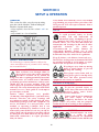
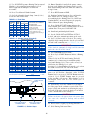
I-HTA-410I
ORIGINAL INSTRUCTIONS
Installation, Setup
and Operation
INSTRUCTIONS
for
SUNNEN® TUBE HONE
Model: HTA-2100 & HTA-4100
READ THE FOLLOWING INSTRUCTIONS THOROUGHLY AND CAREFULLY BEFORE UNPACKING,
INSPECTING, OR INSTALLING THE SUNNEN® TUBE HONE.
“SUNNEN® AND THE SUNNEN LOGO ARE REGISTERED TRADEMARKS OF SUNNEN PRODUCTS COMPANY.”
SUNNEN ® PRODUCTS COMPANY • 7910 MANCHESTER ROAD • ST. LOUIS, MO 63143, U.S.A. • PHONE: 314-781-2100
GENERAL INFORMATION
The Sunnen® equipment has been designed and engineered for a wide variety of parts within the capacity and limitation of the equipment. With proper care
and maintenance this equipment will give years of service.
READ THE FOLLOWING INSTRUCTIONS CAREFULLY AND THOROUGHLY BEFORE UNPACKING, INSPECTING, OR INSTALLING THIS EQUIPMENT.
IMPORTANT: Read any supplemental instructions BEFORE installing this equipment. These supplemental instructions give you important information to
assist you with the planning and installation of your Sunnen equipment.
Sunnen Technical Service Department is available to provide telephone assistance for installation, programming, & troubleshooting of your Sunnen
equipment. All support is available during normal business hours, 8:00 AM to 4:30 PM Central Time.
Review all literature provided with your Sunnen equipment. This literature provides valuable information for proper installation, operation, and maintenance
of your equipment. Troubleshooting information can also be found within the Instructions. If you cannot find what you need, call for technical support.
Where applicable, programming information for your Sunnen equipment is also included. Most answers can be found in the literature packaged with your
equipment.
Help us help you. When ordering parts, requesting information, or technical assistance about your equipment, please have the following
information available:
• Have ALL MANUALS on hand. The Customer Services Representative or Technician will refer to it.
• Have Model Number and Serial Number printed on your equipment Specification Nameplate.
• Where Applicable: Have Drive model and all nameplate data. Motor type, brand, and all nameplate data.
For Troubleshooting, additional information may be required:
• Power distribution information (type - delta, wye, power factor correction; other major switching devices used, voltage fluctuations)
• Installation Wiring (separation of power & control wire; wire type/class used, distance between drive and motor, grounding).
• Use of any optional devices/equipment between the Drive & motor (output chokes, etc.).
For fast service on your orders call:
Sunnen Automotive Customer Service toll free at: 1-800-772-2878
Sunnen Industrial Customer Service toll free at: 1-800-325-3670
Customers outside the USA, contact your local authorized Sunnen Distributor.
Additional information available at: http://www.sunnen.com or e-mail: [email protected]
NOTE: Sunnen reserves the right to change or revise specifications and product design in connection with any feature of our products contained herein.
Such changes do not entitle the buyer to corresponding changes, improvements, additions, or replacements for equipment, supplies or accessories
previously sold. Information contained herein is considered to be accurate based on available information at the time of printing. Should any discrepancy of
information arise, Sunnen recommends that user verify the discrepancy with Sunnen before proceeding.
ESD PREVENTION REVIEW
Let's review the basics of a sound static control system and its effective implementation. First, in the three step plan:
1.
Always ground yourself when handling sensitive components or assemblies.
2.
Always use a conductive or shielded container during storage or transportation. These materials create a Faraday
cage which will isolate the contents from static charges.
3.
Open ESD safe containers only at a static safe work station.
At the static safe work station, follow these procedures before beginning any work:
A.
Put on your wrist strap or foot grounding devices.
B.
Check all grounding cords to make sure they are properly connected to ground, ensuring the effective dissipation of static charges.
C.
Make sure that your work surface is clean and clear of unnecessary materials, particularly common plastics.
D.
Anti-static bubble wrap has been included for use at the machine when an ESD safe workstation is not available.
You are now properly grounded and ready to begin work. Following these few simple rules and using a little common sense will go a long
way toward helping you and your company in the battle against the hazards of static electricity. When you are working with ESD sensitive devices, make sure you:
GROUND
ISOLATE
NEUTRALIZE
ii
SUNNEN® LIMITED PRODUCT WARRANTY
Sunnen® Products Company and its subsidiaries (SPC) warrant that all new SPC honing machines, gaging equipment, tooling, and related equipment will
be free of defects in material and/or workmanship for a period of one year from the date of original shipment from SPC.
Upon prompt notification of a defect during the one-year period, SPC will repair, replace, or refund the purchase price, with respect to parts that prove to be
defective (as defined above). Any equipment or tooling which is found to be defective from improper use will be returned at the customer's cost or repaired
(if possible) at customer's request. Customer shall be charged current rates for all such repair.
Prior to returning any SPC product, an authorization (RMA#) and shipping instructions must be obtained from the Customer Service Department or items
sent to SPC will be returned to the customer.
Warranty Limitations and Exclusions This Warranty does not apply to the following:
• Normal maintenance items subject to wear and tear: (belts, fuses, filters, etc).
• Damages resulting from but not limited to:
› Shipment to the customer (for items delivered to customer or customer's agent F.O.B., Shipping Point)
› Incorrect installation including improper lifting, dropping and/or placement
› Incorrect electric power (beyond +/- 10% of rated voltage) including intermittent or random voltage spikes or drops
› Incorrect air supply volume and/or pressure and/or contaminated air supply
› Electromagnetic or radio frequency interference from surrounding equipment (EMI, RFI)
› Storm, lightning, flood or fire damage
› Failure to perform regular maintenance as outlined in SPC manuals
› Improper machine setup or operation causing a crash to occur
› Misapplication of the equipment
› Use of non-SPC machines, tooling, abrasive, fixturing, coolant, repair parts, or filtration
› Incorrect software installation and/or misuse
› Non-authorized customer installed electronics and/or software
› Customer modifications to SPC software
THE LIMITED WARRANTY DESCRIBED HEREIN IS EXPRESSLY IN LIEU OF ALL ANY OTHER WARRANTIES. SPC MAKES NO REPRESENTATION OR WARRANTY OF ANY
OTHER KIND, EXPRESS OR IMPLIED, WHETHER AS TO MERCHANTABILITY, FITNESS FOR A PARTICULAR PURPOSE OR ANY OTHER MATTER. SPC IS NOT
RESPONSIBLE FOR THE IMPROPER USE OF ANY OF ITS PRODUCTS. SPC SHALL NOT BE LIABLE FOR DIRECT, INDIRECT, INCIDENTAL, OR CONSEQUENTIAL
DAMAGES INCLUDING BUT NOT LIMITED TO: LOSS OF USE, REVENUE, OR PROFIT. SPC ASSUMES NO LIABILITY FOR PURCHASED ITEMS PRODUCED BY OTHER
MANUFACTURERS WHO EXTEND SEPARATE WARRANTIES. REGARDLESS OF ANY RIGHTS AFFORDED BY LAW TO BUYER, SPC's LIABILITY, IF ANY, FOR ANY AND
ALL CLAIMS FOR LOSS OR DAMAGES WITH RESPECT TO THE PRODUCTS, AND BUYER'S SOLE AND EXCLUSIVE REMEDY THEREFORE, SHALL IN ALL EVENTS BE
LIMITED IN AMOUNT TO THE PURCHASE PRICE OF THAT PORTION OF THE PRODUCTS WITH RESPECT TO WHICH A VALID CLAIM IS MADE.
Shipping Damages
Except in the case of F.O.B., Buyer's destination shipments, SPC will not be liable for any settlement claims for obvious and/or concealed shipping damages.
The customer bears the responsibility to unpack all shipments immediately and inspect for damage. When obvious and/or concealed damage is found, the
customer must immediately notify the carrier's agent to make an inspection and file a claim. The customer should retain the shipping container and packing
material.
SUNNEN® SOFTWARE LICENSE AGREEMENT
This document is a Legal Agreement between you, as user and licensee (Licensee), and Sunnen® Products Company (SPC) with respect to preprogrammed
software (Software) provided by SPC for use on SPC Equipment. By using the Software, you, as Licensee, agree to become bound by the terms of this
Agreement.
In consideration of payment of the license fee (License Fee) which is part of the price evidenced by your receipt (Receipt), SPC grants to you as Licensee
a non-exclusive right, without right to sub-license, to use the particular copy of the SPC Software licensed hereunder only on the particular equipment sold with
the Software. SPC reserves all rights including rights not otherwise expressly granted, and retain title and ownership to the Software including all subsequent
copies or updates in any media. The Software and all accompanying written materials are covered by copyrights owned by SPC. If supplied on removable
media (floppy disk), you, as Licensee, may copy the Software only for back up purposes; or you may request that SPC copy the Software for you for the
same purposes. All other copying of the Software or of the accompanying written materials is expressly forbidden and is in violation of the Agreement.
The Software and accompanying written materials (including the user's manual, if any) are provided in an "as is" condition without warranty of any kind
including the implied warranties of merchantability and fitness for a particular purpose, even if SPC has been advised of this purpose. SPC specifically does
not warrant that it will be liable as a result of the operation of the Software for any direct, indirect, consequential or accidental damages arising out of the
use of or inability to use such product even if SPC has been advised of the possibility of such use. It is recognized that some states do not allow the exclusion or limitation of liability for consequential or accidental damages and to the extent this is true, the above limitations may not apply.
Any alteration or reverse engineering of the software is expressly forbidden and is in violation of this agreement.
SPC reserves the right to update the software covered by this agreement at any time without prior notice and any such updates are covered by this
agreement.
iii
SAFETY INSTRUCTIONS
READ FIRST
This machine, like any equipment, may be dangerous if used improperly. Please
read all warnings and instructions before attempting to use this machine.
Always disconnect power at main enclosure before servicing machine.1
Always wear eye protection when operating this machine.
NEVER open or remove any machine cover or protective guard with power "ON."
Always disconnect power at main enclosure before servicing this equipment.1
DO NOT attempt any repair or maintenance procedure beyond those described in
this book. Contact your Sunnen® Field Service Engineer or Technical Services
Representative for repairs not covered in these instructions.
Due to the wide variety of machine configurations, all possibilities cannot be
described in these instructions. Instructions for safe use and maintenance of
optional equipment ordered through Sunnen, will be provided through separate
documentation and/or training provided by your Sunnen Field Service Engineer or
Technical Services Representative.
DO NOT attempt to defeat any safety device on this machine or on any of the
optional equipment.
If specially built automation components are added to this system, be sure that
safety is not compromised. If necessary, obtain special enlarged work area safety
system from Sunnen Products Co.
1
DO NOT touch electrical components until main input power has been turned off and CHARGE
lamps are extinguished. WARNING: The capacitors are still charged and can be quite dangerous.
iv
TABLE OF CONTENTS
Page
TABLE OF CONTENTS . . . . . . . . . . . . . . . . . . . . . . . . . . . . . . . . . . . . . . . . . . . . . . . . . . . . . . . . . . . . . . . . v
LIST OF APPENDIXES . . . . . . . . . . . . . . . . . . . . . . . . . . . . . . . . . . . . . . . . . . . . . . . . . . . . . . . . . . . . . . . . v
INTRODUCTION . . . . . . . . . . . . . . . . . . . . . . . . . . . . . . . . . . . . . . . . . . . . . . . . . . . . . . . . . . . . . . . . . . . . vi
GENERAL INFORMATION & SPECIFICATIONS . . . . . . . . . . . . . . . . . . . . . . . . . . . . . . . . . . . . . . . . vii
FLOOR LAYOUT (Configuration) . . . . . . . . . . . . . . . . . . . . . . . . . . . . . . . . . . . . . . . . . . . . . . . . . . . . . . viii
INSTALLATION . . . . . . . . . . . . . . . . . . . . . . . . . . . . . . . . . . . . . . . . . . . . . . . . . . . . . . . . . . . . . . . . . . . . . . . 1
Purpose . . . . . . . . . . . . . . . . . . . . . . . . . . . . . . . . . . . . . . . . . . . . . . . . . . . . . . . . . . . . . . . . . . . . . . . . . . . . . . 1
Tooling & Materials . . . . . . . . . . . . . . . . . . . . . . . . . . . . . . . . . . . . . . . . . . . . . . . . . . . . . . . . . . . . . . . . . . . . 1
Installation . . . . . . . . . . . . . . . . . . . . . . . . . . . . . . . . . . . . . . . . . . . . . . . . . . . . . . . . . . . . . . . . . . . . . . . . . . . . 1
Electrical Requirements . . . . . . . . . . . . . . . . . . . . . . . . . . . . . . . . . . . . . . . . . . . . . . . . . . . . . . . . . . . . . . . . . . 3
Electrical Connection . . . . . . . . . . . . . . . . . . . . . . . . . . . . . . . . . . . . . . . . . . . . . . . . . . . . . . . . . . . . . . . . . . . 3
Safety Arch Switch . . . . . . . . . . . . . . . . . . . . . . . . . . . . . . . . . . . . . . . . . . . . . . . . . . . . . . . . . . . . . . . . . . . . . 4
Optional Light Curtain . . . . . . . . . . . . . . . . . . . . . . . . . . . . . . . . . . . . . . . . . . . . . . . . . . . . . . . . . . . . . . . . . . 5
Light Curtain Function Check . . . . . . . . . . . . . . . . . . . . . . . . . . . . . . . . . . . . . . . . . . . . . . . . . . . . . . . . . . . . .6
PREPARING FOR OPERATION . . . . . . . . . . . . . . . . . . . . . . . . . . . . . . . . . . . . . . . . . . . . . . . . . . . . . . . . . . 9
General . . . . . . . . . . . . . . . . . . . . . . . . . . . . . . . . . . . . . . . . . . . . . . . . . . . . . . . . . . . . . . . . . . . . . . . . . . . . . . 9
Major Components . . . . . . . . . . . . . . . . . . . . . . . . . . . . . . . . . . . . . . . . . . . . . . . . . . . . . . . . . . . . . . . . . . . . . 9
Operator Controls . . . . . . . . . . . . . . . . . . . . . . . . . . . . . . . . . . . . . . . . . . . . . . . . . . . . . . . . . . . . . . . . . . . . . . 9
Safety Symbols . . . . . . . . . . . . . . . . . . . . . . . . . . . . . . . . . . . . . . . . . . . . . . . . . . . . . . . . . . . . . . . . . . . . . . . . 9
Honing Tool . . . . . . . . . . . . . . . . . . . . . . . . . . . . . . . . . . . . . . . . . . . . . . . . . . . . . . . . . . . . . . . . . . . . . . . . . . . 9
Workholding Fixture . . . . . . . . . . . . . . . . . . . . . . . . . . . . . . . . . . . . . . . . . . . . . . . . . . . . . . . . . . . . . . . . . . . 11
SETUP AND OPERATION . . . . . . . . . . . . . . . . . . . . . . . . . . . . . . . . . . . . . . . . . . . . . . . . . . . . . . . . . . . . . .
General . . . . . . . . . . . . . . . . . . . . . . . . . . . . . . . . . . . . . . . . . . . . . . . . . . . . . . . . . . . . . . . . . . . . . . . . . . . . .
Safety Precautions . . . . . . . . . . . . . . . . . . . . . . . . . . . . . . . . . . . . . . . . . . . . . . . . . . . . . . . . . . . . . . . . . . . . .
Operating Hints . . . . . . . . . . . . . . . . . . . . . . . . . . . . . . . . . . . . . . . . . . . . . . . . . . . . . . . . . . . . . . . . . . . . . . .
Setup & Operation . . . . . . . . . . . . . . . . . . . . . . . . . . . . . . . . . . . . . . . . . . . . . . . . . . . . . . . . . . . . . . . . . . . . .
13
13
14
14
14
ROUTINE MAINTENANCE . . . . . . . . . . . . . . . . . . . . . . . . . . . . . . . . . . . . . . . . . . . . . . . . . . . . . . . . . . . .
General . . . . . . . . . . . . . . . . . . . . . . . . . . . . . . . . . . . . . . . . . . . . . . . . . . . . . . . . . . . . . . . . . . . . . . . . . . . . .
Cleaning . . . . . . . . . . . . . . . . . . . . . . . . . . . . . . . . . . . . . . . . . . . . . . . . . . . . . . . . . . . . . . . . . . . . . . . . . . . .
Lubrication . . . . . . . . . . . . . . . . . . . . . . . . . . . . . . . . . . . . . . . . . . . . . . . . . . . . . . . . . . . . . . . . . . . . . . . . . .
Coolant Line Check . . . . . . . . . . . . . . . . . . . . . . . . . . . . . . . . . . . . . . . . . . . . . . . . . . . . . . . . . . . . . . . . . . . .
Coolant Reservoir . . . . . . . . . . . . . . . . . . . . . . . . . . . . . . . . . . . . . . . . . . . . . . . . . . . . . . . . . . . . . . . . . . . . .
Auto Feed Clutch Adjustment . . . . . . . . . . . . . . . . . . . . . . . . . . . . . . . . . . . . . . . . . . . . . . . . . . . . . . . . . . . .
Handwheel & Armature Removal . . . . . . . . . . . . . . . . . . . . . . . . . . . . . . . . . . . . . . . . . . . . . . . . . . . . . . . . .
Feed Clutch . . . . . . . . . . . . . . . . . . . . . . . . . . . . . . . . . . . . . . . . . . . . . . . . . . . . . . . . . . . . . . . . . . . . . . . . . .
Light Curtain Cleaning . . . . . . . . . . . . . . . . . . . . . . . . . . . . . . . . . . . . . . . . . . . . . . . . . . . . . . . . . . . . . . . . .
17
17
17
17
18
18
18
19
20
20
TROUBLESHOOTING . . . . . . . . . . . . . . . . . . . . . . . . . . . . . . . . . . . . . . . . . . . . . . . . . . . . . . . . . . . . . . . . . 21
General . . . . . . . . . . . . . . . . . . . . . . . . . . . . . . . . . . . . . . . . . . . . . . . . . . . . . . . . . . . . . . . . . . . . . . . . . . . . . 21
Operational Troubleshooting . . . . . . . . . . . . . . . . . . . . . . . . . . . . . . . . . . . . . . . . . . . . . . . . . . . . . . . . . . . . . 21
APPENDIXES
A Check List, Setup & Operation . . . . . . . . . . . . . . . . . . . . . . . . . . . . . . . . . . . . . . . . . . . . . . . . . . . . . . . . .
B Crosshatch Angle . . . . . . . . . . . . . . . . . . . . . . . . . . . . . . . . . . . . . . . . . . . . . . . . . . . . . . . . . . . . . . . . . . . .
C Coolant Flow Diagram . . . . . . . . . . . . . . . . . . . . . . . . . . . . . . . . . . . . . . . . . . . . . . . . . . . . . . . . . . . . . . . .
D Surface Roughness Table . . . . . . . . . . . . . . . . . . . . . . . . . . . . . . . . . . . . . . . . . . . . . . . . . . . . . . . . . . . . . .
E Alignment of 4M Machines . . . . . . . . . . . . . . . . . . . . . . . . . . . . . . . . . . . . . . . . . . . . . . . . . . . . . . . . . . . . .
F Declaration of Conformity . . . . . . . . . . . . . . . . . . . . . . . . . . . . . . . . . . . . . . . . . . . . . . . . . . . . . . . . . . . . .
v
23
25
27
29
31
33
INTRODUCTION
This Instruction Manual is provided to give the information required to install, operate, and maintain the
Sunnen® HTA-Series Tube Hones, models HTA-2100 & -4100.
As there are numerous Workpieces that can be honed on this machine, all possible combinations cannot be
discussed here. The determining factor as to whether a particular part or material can be honed in the machine
will come with experience from working with the machine in your shop.
When ordering parts for, or requesting information about your machine, include the serial number of your
machine.
READ THE FOLLOWING INSTRUCTION THOROUGHLY BEFORE UNPACKING, INSPECTING, OR
INSTALLING THE SUNNEN® TUBE HONE.
vi
GENERAL INFORMATION & SPECIFICATIONS
Sunnen® Tube Hone - HTA-Series
Model:
HTA-2100
HTA-4100
Workpiece Ø Range (ID) :
64 - 533 mm (2.5 - 21 in.)
Workpiece Ø Range (OD)1:
38 - 610 mm (1.5 - 24 in.)2
1
Workpiece Weight1:
Stroke Length Range1:
2
3630 kg (8000 lbs.)
Up to 2,1 m (6.9 ft / 82.7 in.)
Up to 4,1 m (13.5 ft / 161.4 in.)
Stroke Rate:
1,52 - 27,4 mpm (5 - 90 fpm)
Stroke Motor:
1,48 kW (2 hp)
Spindle Speeds:
20 to 300 rpm
Spindle Motor:
2,24 kW (3 hp) AC gear motor
Set-Up Time:
10 - 15 min.
Stock Removal Rate3:
130 cm3/hr (8 in3/hr)
Coolant Pump:
Centrifugal pump
Pump Motor:
0,248 kW (1/3 hp)
Coolant Capacity:
182 L (48 gal.)
Pump Rate:
225 LPM (60 GPM)
Coolant Requirements:
Sunnen Industrial Honing Fluids
Controls:
Siemens PLC with Touch Screen
Floor Space Length:
Depth:
Height:
Floor Weight (Dry):
4790 mm (189 in.)
987 mm (39 in.)
1501mm (59 in.)
1088 kg (2400 lbs.)
Floor Load:
Electrical Requirements:
1815 kg (4100 lbs.)
739 kg/sq. meter (151 lbs./sq. ft)
400/460V, 50/60Hz, 3Ph, 15A (Designed in accordance with NEC/NFPA 79)
Color:
Noise Emission:
9580 mm (385 in.)
987 mm (39 in.)
1501 mm (59 in.)
Black
Less than 76 dB(A) continuous
Less than 78 dB(A) peak
Load (max. noise) condition in a typical factory environment.
Diameter range, length range, and workpiece weight are contingent on workpiece and application.
For diameter sizes below 64mm (2.5in.), contact your local Sunnen Field Service Engineer.
3
For steel material with conventional abrasives. Actual stock removal rates will vary depending on workpiece and application.
1
2
vii
839
1310
839
4790
9580
4790
4790
4790
1310
1310
734
1501
987
734
987
FLOOR PLAN - Sunnen® Tube Hones
viii
1310
1501
SECTION 1
INSTALLATION
l HTA-2100 ONLY:
a. Machine Base should be lifted in center of Base, from
either front or back side (see Figure 1-2).
b. Using a machinist level, level machine by
adjusting Leveling Setscrews in Support feet, using
a 1-1/8 Open End Wrench (see Figure 1-4).
l HTA-4100 ONLY:
a. Carriage Base should be lifted in center of Base, from
either front or back side (see Figure 1-2). Then
Workpiece Base should be lifted in center of Base,
and set it in line with Carriage Base (see Figure 1-3).
b. Remove Cover Plate (see Figure 1-5).
PURPOSE
This Section is designed to aid user in unpacking,
inspecting, and installing Sunnen® Tube Hone,
models HTA-2100 & -4100. Hereafter, referred to
as the Machine (see Figure 1-1).
TOOLS & MATERIALS
The following tools and materials are required for
unpacking and installing machine:
Wire Cutters/Strippers
Knife
Screw Driver (Std. nose) Hammer
Slip-Joint Pliers
Crow Bar
Cleaning Solvent
Tin Snips
Open End Wrench (17, 19, & 24 mm / 3/4in.)
NOTE: If needed: Refer to I-HTA-555, Special
Instructions for cover removal.
INSTALLATION
Read the following instructions carefully and
thoroughly before unpacking, inspecting, and
installing the Machine. All references to right and
left in these instructions are, unless otherwise noted,
as seen by operator as one looks at Machine or
assembly being described.
c. Slide two sections together.
d. Utilizing a string or wire, align operator side of
both Workpiece & Carriage Bases (refer to Figure 1-3).
e. Using a machinist level, level Carriage Base by
adjusting Leveling Setscrews in Support feet, using
a 1-1/8 Open End Wrench (see Figure 1-4).
1. Remove heavy duty plastic wrap from around
shipping crate.
WARNING
Use safety glasses or goggles when cutting bands.
2. Cut, remove and discard shipping bands.
HTA 2100
3. Remove Components from crate.
FORKS POSITION
4. Remove items shipped inside Coolant Reservoir.
5. Remove nuts and bolts securing Base(s) to
bottom of crate(s); use 3/4" Open End Wrench.
6. Using a fork lift. Remove Base(s) from skid and
set it in place, as follows:
HTA 4100
CARRIAGE BASE
HTA 4100
WORKPIECE BASE
FORKS POSITION
FORKS POSITION
RIGHT
LEFT
FRONT
FIGURE 1-2, Lifting Machines
FIGURE 1-1, Tube Hone
1
FORKS POSITION
FORKS POSITION
CARRIAGE BASE
WORKPIECE BASE
ALIGN BASES
USING
STRING or WIRE
FIGURE 1-3, Connecting Tables (HTA4100)
f. Align holes in Workpiece Base with Carriage Base
and install bolts securing two sections together.
NOTE: Use sealant on washer inner faces to prevent
oil leakage.
g. Using a machinist level, level Workpiece Base by
adjusting Leveling Setscrews in Support feet, using
a 1-1/8 Open End Wrench (refer to Figure 1-4).
h. Install Cover Plate as shown (refer to Figure 1-5).
NOTE: If needed: Refer to I-HTA-555, Special
Instructions for cover installation.
LEVELING
BOLT (1-1/8”)
& LOCKNUT
7. Inspect Machine and Components for dents,
scratches, or damage resulting from improper
handling by carrier. If damage is evident,
immediately file a claim with carrier.
FIGURE 1-4, Leveling Screws
8. For permanent installation, secure Machines
Support Feet to Floor with appropriate fasteners
(not supplied).
REFER TO SPECIAL
INSTRUCTIONS FOR
INSTALLING COVER PLATE
COVER
PLATE
9. HTA-4100 ONLY: The Workpiece Base has one
E-Stop that must be connected to Carriage Base.
l E-Stop cable will be routed and connected later
under Safety Arch Installation.
CABLE
10. Remove all packing materials.
(SAFETY
ARCH)
11. Remove bolt securing Operator Control Console
and move Arm to operator position. Then install
grub screw to limit arm movement (see Figure 1-6).
l Route and connect electrical plug to Main
Electrical Enclosure.
12. Remove packing material from two (2) Splash
Guards on Machine (see Figure 1-7).
COMMON
PLUG
CABLE
(E-STOP)
FIGURE 1-5, Cover Plate
2
(HTA-4100 ONLY)
13. Install coolant reservoir under machine and connect
coolant hoses (see Figure 1-8).
l Connect coolant intake and outlets supply lines to
machines.
l Route and connect Pump Electrical Plug to Main
Electrical Enclosure.
14. Check Coolant Nozzles (see Figure 1-9).
OPERATOR
CONTROL
CONSOLE
15. Clean Spindle Carriage Ways with solvent to
remove antirust and any foreign materials.
16. After cleaning Spindle Carriage Ways. Lightly
lubricate with Mobil Way Oil 300 or equivalent.
ELECTRICAL REQUIREMENTS
All wiring is to be performed by a competent, Licensed
Electrician in accordance with all local, state, and
federal codes and regulations; along with any special
information provided on machine nameplate or
electrical specification plate.
FIGURE 1-6, Operator Control Console
SPLASH
GUARD
WARNING
All wiring and electrical equipment service should
be performed by authorized personnel ONLY.
CAUTION
Note model electrical supply requirement printed on
machine nameplate or electrical specification plate.
Do not attempt to connect machine if supply voltage
is not following acceptable limits as noted on
nameplate or electrical specification plate. If supply
voltage is not within these limits MACHINE WILL
BE DAMAGED.
Verify supply voltage is same as voltage on Machine
Nameplate or Electrical Specifications Plate.
FIGURE 1-7, Splash Guard
ELECTRICAL
PLUG
INPUT
DUMP
TUBE
PAPER
FILTER
OUTPUT
COOLANT
LINE
PUMP
SIGHT
GAGE
FIGURE 1-8, Coolant Reservoir
3
POWER
CORD
COOLANT
NOZZLES
FIGURE 1-9, Coolant Nozzles
FIGURE 1-10, Route Cord
ELECTRICAL CONNECTION
MASTER
ON/OFF
SWITCH
Connect incoming Electrical Supply Cord (not
supplied) to the Machine as follows (see
Figures 1-10 & 1-11).
NOTE: 380V machines require a H12-4 SJO or
SO electrical supply cord; 460V machines require a
4FJ2-4SJO or SO electrical supply cord.
NAMEPLATE
CAUTION
Doors should be closed and latched during operation
to prevent accidental interruption of operation from
doors being opened.
1. If applicable: Loosen Safety Latches on door(s) to
enclosure, using a screwdriver and open Door.
WARNING
Residual Voltage exists for 2-3 minutes after
Master ON/OFF Switch is turned OFF. Before
working inside Enclosure, wait for all fans to stop
running to allow drives to discharge.
2. The machine has been shipped without the
master ON/OFF switch install. Locate master
ON/OFF switch in base of electrical enclosure.
Then, install Master ON/OFF Switch in Door and
secure with two screws.
ELECTRICAL
DISCONNECT
BLOCK
ELECTRICAL
DISCONNECT
BLOCK
WARNING
You must use hole provided. Drilling any new holes in
electrical enclosure may void machine warranty.
3. Route Electrical Supply Cord to Electrical
Enclosure (refer to Figure 1-10).
4. Remove hole plug from entrance hole in enclosure
and install an approved oil tight fitting (not supplied).
5. Insert Electrical Supply Cord through Oil Tight
Fitting and route to Electrical Disconnect Block.
Allow for approximately 305 mm of cable from
where it enters Enclosure; then cut off excess (refer
to Figure 1-11).
RED
GRN
SUPPLY
CORD
YEL
L2
L1
GND
L3
BLK
PRE-DRILLED
HOLE
FIGURE 1-11, Electrical Enclosure
6. Strip 153 mm (6 in.) off cable's outer jacket.
4
SWITCH
CABLE
SWITCH
SAFETY
ARCH
HTA4100
SAFETY ARCH
HTA2100
COMMON
PLUG
E-STOP
(HTA4100)
E-STOP CABLE
(HTA4100)
FIGURE 1-12, Safety Arch Switch
SENDER UNIT LIGHTS
Floating Blanking Light indicates that one or more of the beams
(Receiver)
has been deactivated. This light should not
be illuminated. If it is, contact a Sunnen
representative for repair.
Machine Run
Light indicates the protected machine is
(Receiver)
allowed to operate
Machine Stop
(Receiver)
Light indicates the protected machine is not
allowed to operate
Interlock
(Receiver)
Light indicates the protected machine is not
allowed to operate until the protected zone is
cleared and the start button is pressed and
released
Status Indicator
(Transmitter)
Indicates the light curtain is functional
FIGURE 1-13, Light Curtain
SAFETY ARCH
7. Strip 6 mm (1/4 in.) of insulation off each wire.
8. Connect Green Wire (GRN) to Ground Terminal
beside Electrical Disconnect Block (Earth Ground).
9. Connect other three wires to Disconnect Block
(CB1) as noted on Block (L1, L2, L3).
10. Route and secure Cord inside of Enclosure.
11. Tighten Oil Tight Fitting.
12. Close and secure/lock Door to Enclosure. .
(Doors WILL NOT open unless Master ON/OFF
Switch is in OFF position.)
13. Route and connect Electrical Supply Cord to power
source. (PLUG Machine's Electrical Supply Cord into a
properly polarized grounding-type wall receptacle.)
14. Turn ON Master ON/OFF Switch. (Doors WILL
NOT open unless Master ON/OFF Switch is in OFF
position.)
Machine comes with a Safety Arch Assembly
attached to the Workpiece Base. The Safety Arch
Assembly has a Switch that detects when the arch is
opened. This Switch is prewired to be connected to
the Main Electrical Enclosure and is assembled on
Safety Arch. Install Arch as follows (see Figure 1-12).
1. Remove packing materials.
2. Route Safety Arch Switch Cable behind and
under machine.
l Attach Safety Arch Switch Cable (and E-Stop Cable
-HTA-4100 only) along lower front section of carriage
base with provided cable ties.
l Then connect to Main Electrical Enclosure.
NOTE: The operational position of the switch with
its bracket is preset at the factory but should be
checked after installation. The switch should activate
any time the arch is opened.
5
l If switch activation point needs to be reset,
LIGHT CURTAIN FUNCTION TEST
reposition switch up or down using vertical slots in
switch bracket. Take care that switch is not set too
high causing roller plunger on switch to not have
any travel left when safety arch is opened.
(CE Machines Only) Check Light Curtain operation
as follows(see Figure 1-16):
WARNING
The test outlined below must be performed at
installation, according to employer’s regular
inspection program and after any maintenance,
tooling change, setup, adjustment, or modification to
Light Curtain System or the guarded machine.
Where a guarded machine is used by multiple
operators or shifts, it is suggested that the test be
performed at each shift or operation change. Testing
ensures that Light Curtain and machine control
system work properly to stop the machine. Failure to
test properly could result in injury to personnel.
3. With machine at rest. Verify that machine will
not start when safety arch is opened.
4. Verify that braking system is working properly.
Machine must come to a quick controlled stop when
safety arch is opened. Drive faults, spindle coasting
and stroker coasting are unacceptable.
OPTIONAL LIGHT CURTAIN
(CE Machines Only) CE machines come with
optional Light Curtain and guarding installed. Light
Curtain alignment must be tested for proper
function after machine installation. To check,
proceed as follows (see Figure 1-13):
MOUNTING
BRACKET
1. Set Light Curtain to a height of 855mm as
shown (see Figure 1-14).
l Check for signs of external damage to the light
curtain transmitter, receiver, or cables and wiring.
2. Connect Light Curtain Cables to Light Curtain
Receiver and Transmitter as shown (see Figure 1-15).
l Inspect electrical connections between guarded
machine’s control system and light curtain. Verify
they are properly connected.
LIGHT
CURTAIN
855mm
3. Turn on power to machine.
1 2 3 4
5 6
DIP
SWITCH
5 6
1 2 3 4
4. Verify that curtain is in alignment. The individual
beam indicators located on receiver will illuminate
when alignment of a beam is not met (refer to
Figure 1-13).
ON
ON
FIGURE 1-14, Light Curtain Height
ROUTE CABLE TO LIGHT
CURTAIN RECEIVER
SAFETY ARCH
SWITCH CABLE
COOLANT CART
CABLE
LIGHT CURTAIN
CABLE
ROUTE CABLE TO LIGHT
CURTAIN TRANSMITTER
FIGURE 1-15, Light Curtain Cable Connections
6
(CE Machines ONLY)
2. Start machine. While machine is in motion,
interrupt detection zone with test object. Machine
should stop immediately. Never insert test object
into dangerous parts of machine.
3. With machine at rest, interrupt detection zone
with test object. Verify that machine will not start
with test object in detection zone.
OP
ST
4. Verify that braking system is working properly.
Machine must come to a quick controlled stop when
light curtain is interrupted. Drive faults, spindle
coasting and stroker coasting are unacceptable.
T
AR
ST
OPERATIONAL CHECK
Read IOM Instructions, Sections 1 and 2 thoroughly
and carefully before performing Operational Check.
1. Operate Machine and check rotation of Coolant
Pump. Rotation is indicated on pump fan cover. If
rotation is incorrect, reverse any two wires (red,
white, or black) of electrical supply cord, where they
connect to Disconnect Block.
2. Set up and test all machine functions (refer to
Section 3, Setup & Operation).
3. After unpacking and installing Machine, clean
and lubricate (refer to Section: 4, Routine Maintenance).
FIGURE 1-16, Light Curtain
WARNING
When light curtain key switch is deactivated a
cycle cannot begin, however, if machine is in middle
of a cycle and switch is flipped, machine will finish
its stroke in that cycle and then come to a complete
stop.
1. Interrupt light curtain system with proper size
test object (Test object size: 30 mm diameter).
When using the test object, guide it through the
detection zone as shown below. At least one
individual beam indicator must be lit while test
object is anywhere in detection zone.
7
NOTES
8
SECTION 2
PREPARING FOR OPERATION
GENERAL
HONING TOOL
Consult this section when preparing Machine for
operation.
Assembly and install Honing Tool per instructions
packaged with Tooling.
1. Assemble Honing Tool (see Figure 2-3).
MAJOR COMPONENTS
For location of major components on machine (see
Figure 2-1).
NOTE: The HTA is designed to use both ANR and
MPS driveshaft extensions. ANR shafts are designed
to bolt together and MPS shafts are designed to screw
together. Thus, when using ANR Tooling on a MPS
Driveshafts, a MPS2220A Output Adapter must be
used (refer to Figure 2-3)
OPERATOR CONTROLS
For location and function of Operator Controls (see
Figure 2-2 & Table 2-1).
SAFETY SYMBOLS
2. Guide Honing Tool into the bore.
For a description of safety symbols that may be
used on this machine refer to Table 2-2.
3. Align Input Yoke Adapter on Honing Tool with
Drive Ring, and guide adapter onto Hex Shaft (see
Figure 2-4).
SPLASH
GUARDS
FEED CLUTCH
HANDWHEEL
OPERATOR
CONTROL
CONSOLE
COOLANT
RESERVOIR
ELECTRICAL
ENCLOSURE
CARRIAGE
BASE
FIGURE 2-1, Major Components
9
WORKPIECE
BASE
R
1
6
R
3
2
4
5
FIGURE 2-2, Operator Control Panel
TABLE 2-1, Operator Control Panel
1
LCD Display and
Touch-Screen
Operator Panel.
Operation of the machine can generally be done via the touch screen, which means
that a function may be started by touching the corresponding key on the screen
2
SAFETY /
Stop the machine in a emergency situation
EMERGENCY STOP
3
Hardware Cycle
START Button
Start the honing cycle if the machine is in AUTO
4
Hardware Cycle
STOP Button
Stop the honing cycle.
5
Joystick for manual
Stroke movement
Manual movement of the carriage for setup and to over ride the AUTO mode
operating direction. (left / right)
6
Light Curtain
(Key Switch)
(CE Models ONLY) Key Activated Light Curtain. Machine will automatically Stop
when light beam is interrupted.
TABLE 2-3, Safety Symbols
SYMBOL
DESCRIPTION
FUNCTION
Warning Label
Warns that an electrical hazard exists.
Warning Label
Warns that safety glasses should be worn at all times when operating
this machine.
Warning Strip
Warns that a physical hazard exists, and that proper precautions should
be taken.
Label
Designates this machine is “CE” compliance.
Warning
Label
Warns that a hazard from objects falling off work table exists and that proper
precautions should be taken.
Warning
Label
Warns not to hold workpiece in hand without a torque
resisting fixture.
Warning Label
Warns that an arc flash hazard exists.
10
DRIVE SHAFT EXTENSION
MPS-E______
MPS-2211A
Input Drive
Adapter
MPS-2220A
Output Adapter
MPS-2221A
Output Drive
Adapter
MPS-2222A
Output Feed
Adapter
MPS-2212A
Input Feed
Adapter
MPS-175
U-JOINT
MPS-2230A
MPS-ER22
Adapters to Convert MPS Driveshaft to Bolt
Together Configuration (ANR Style) (Option)
One of each part number required per MPS
driveshaft.
MPS-2235A DRIVE SHAFT EXTENSION
MPS-E2015 (5.9"/150 mm)
MPS-2220A
Output Adapter
DRIVE SHAFT EXTENSION
ANR-741 (9.25"/235 mm)
ANR-742 (19"/483 mm)
ANR-744 (42.75"/1086 mm)
ANR-746 (72.25"/1835 mm)
ANR-160
HONE HEAD
ANR Style - Bolt Together Style: Requires MPS-E2015 and MPS-2220A to connect to HTA U-Joint
MPS-175
U-JOINT
MPS-2230A
MPS-ER22
MPS-2235A
DRIVE SHAFT EXTENSION
MPS-E2015 (5.9"/150 mm)
MPS-E2040 (15.7"/400 mm)
MPS-E2100 (39.3"/1000 mm)
MPS-E2160 (63"/1600 mm)
MPS-2220A
Output Adapter
ANR-160
HONE HEAD
MPS Style - Screw Together: Connects directly to HTA U-Joint
FIGURE 2-3, HTA Drive Shaft Comparison for use with ANR-Style Hone
4. Rotate input Yoke Adapter (clockwise) to engage
and Lock into the Drive Ring on the Spindle Nose.
5. Slide Rubber Boot over Input Yoke Adapter
(refer to Figure 2-4).
TRIP
LEVER
WORKHOLDING FIXTURE
DRIVE
RING
Position the Workholding Fixture as follows (see
Figure 2-5):
1. Turn OFF all electrical power.
HEX
SHAFT
3. Position Fixture so Workpiece will be clamped
close to its Ends (approx. 300-500mm).
Configure Fixture height so centerline of Workpiece
aligns with centerline of Spindle (refer to Figure 2-5).
ADJUSTABLE
STROKE
STOP
INPUT YOKE
ADAPTER
2. Loosen four Socket Head Capscrews in base of
Workholding Fixtures (see Figure 2-6).
UNIVERSAL
COVER
HONING
TOOL
4. Lift Workpiece into Machine, using a hoist as
required.
5. Place tool inside Workpiece bore and snug tool
with Handwheel.
CENTERLINE
6. Place a level on driveshaft and raise or lower Screw
Assembly on Workholding Fixture until driveshaft is
level.
The centerline of the Workpiece should be in line
with the centerline of the spindle.
7. Wrap Chains around Workpiece and through
Wedge Clamps. Secure by inserting Locking Pins
and Clevis Pins (refer to Figure 2-6).
8. Adjust tension on Chains using Clamp Handle.
Hand tighten to approximately 40-50 N/m
(2.8-3.5 lbs/ft).
FIGURE 2-4, Input Yoke Adapter
11
9. Tighten four Capscrews in base of each
Workholding Fixture (refer to Figure 2-6).
CAUTION
Use care when tightening chains - Over tightening
may distort workpiece.
H
FIXTURE
HEIGHT
mm
in.
140
5.4
126
4.9
112
4.3
98
3.8
85
3.2
71
2.7
58
2.2
48
1.6
31
1.1
18
0.6
610mm
24.0 in.
Ø
WORKPIECE
O.D.
in.
9.0
10.0
11.0
12.0
13.0
14.0
15.0
16.0
17.0
18.0
mm
225
250
275
300
325
350
375
400
425
450
565mm
22.2 in.
H
FIXTURE
HEIGHT
mm
in.
143
5.6
128
5.0
115
4.4
101
3.9
87
3.3
73
2.8
60
2.2
46
1.7
33
1.2
19
0.6
530mm
20.9 in.
Ø
WORKPIECE
O.D.
in.
7.0
8.0
9.0
10.0
11.0
12.0
13.0
14.0
15.0
16.0
mm
175
200
225
250
275
300
325
350
375
400
500mm
19.7 in.
H
FIXTURE
HEIGHT
mm
in.
224
8.8
216
8.5
201
7.9
186
7.3
172
6.7
157
6.1
143
5.6
129
5.0
115
4.4
101
3.9
87
3.3
475mm
18.7 in.
Ø
WORKPIECE
O.D.
in.
1.5
2.0
3.0
4.0
5.0
6.0
7.0
8.0
9.0
10.0
11.0
mm
38
50
75
100
125
150
175
200
225
250
275
10. Tighten Clamp Collar Screw on Fixture Base.
NOMINAL OD
Ø
Ø
Ø
Ø
H
H
H
FIXTURE CLAMPS
POSITIONED ON TOP
OF MACHINE BASE
WORKPIECE OD
38-280 mm (1.5-11.0 in.)
WORKPIECE OD
175-410 mm (6.9-16.0 in.)
WORKPIECE OD
225-460 mm (8.9-18.0 in.)
WORKPIECE OD
475-610 mm (18.7-24.0 in.)
FIGURE 2-5, Fixture
CLEVIS PIN
WEDGE
CLAMPS
CLAMP
HANDLE
CLAMP
HANDLE
CHAIN
CHAIN
SCREW
ASSEMBLY
CAPSCREWS
LOCKING
NUT
CLAMP COLLAR
SCREW
FIGURE 2-6, Fixture
12
LOCKING
PIN
“THINK!”
SAFETY
SECTION 3
SETUP & OPERATION
FIRST AND ALWAYS
GENERAL
If any doubt arises about the correct, safe method
of performing any steps of these procedures, DO
NOT proceed. Seek out expert assistance from a
qualified person.
This section describes a step-by-step operating
procedure for the Machine. Prior to starting the
Machine, Operator shall ensure:
• All prerequisites described in sections 1 and 2 are
complete.
• All personnel are clear of machine.
General
WARNING
To avoid personal injury or death,
carefully read and understand all
instructions before attempting to operate
any equipment. DO NOT operate or work on a
machine unless you read and understand the
instructions and warnings in this and all other
applicable
manuals.
Go
online
to
www.sunnen.com or contact Sunnen for
replacement manuals. Proper care is your
responsibility. Always follow all State and Federal
health and safety laws and/or local regulations.
Keep all visitors a safe distance from work area.
DO NOT use in dangerous environment. DO NOT
use machines in damp or wet locations, or expose
them to rain. Keep work area well lighted.
Keep fingers away from any moving
parts or pinch points to prevent
pinching and crushing.
“THINK!”
SAFETY
FIRST AND ALWAYS
SAFETY PRECAUTIONS
The following precautions should be followed to
ensure maximum safety of personnel while working
on or around Machine.
WARNING
Most accidents occur through failure to
observe basic safety rules and/or operating
procedures. Accident can be avoided by
being alert and recognizing potentially hazardous
situations before an accident occurs. Individuals
performing operation, maintenance, and/or repair
should have the necessary training, skills, and
tools required to perform the functions properly
and safely. The safety information provided in this
manual serves as a basic guide in an attempt to
prevent injury or death.
Sunnen cannot anticipate every possible
circumstance that might involve a potential safety
hazards. Therefore, the safety warnings and
precautions presented in this manual and other
instructions packaged with this equipment can
not be all inclusive. If a tool, procedure, work
method, or operating technique that is not
specifically mentioned by Sunnen is used, you
must satisfy yourself that it is safe for you and for
others. Make sure the product or machine will not
be damaged or be made unsafe by any operation,
lubrication, maintenance, or repair procedures
that you choose.
Wear proper safety items such as,
safety glasses, gloves, non-slip safety
shoes and other personal safety
equipment as necessary or required.
“THINK!”
SAFETY
SAFETY
SAFETY
SAFETY
SAFETY
SAFETY
Installation & Maintenance
WARNING
To prevent personal injury or
death, always disconnect the main
electrical power source before
opening the electrical control box.
Contact with electrical components
may cause injury or death.
Completely disconnect the main
power, remove all jewelry, and use properly
insulated tools when working on this equipment.
“THINK!”
“THINK!”
“THINK!”FIRST AND ALWAYS
FIRST AND
AND ALWAYS
ALWAYS
FIRST
FIRST AND ALWAYS“THINK!”
Work Area
WARNING
Personal injuries can occur
as a result of using
pressurized air. Maximum
air pressure at the nozzle must be below 205 kPa (30
“THINK!”
“THINK!”
“THINK!”FIRST AND ALWAYS
“THINK!”
FIRST“THINK!”
AND ALWAYS
ALWAYS
FIRST
AND
“THINK!”
13
”
OPERATING HINTS
psi) for cleaning purposes. Wear protective
clothing, protective glasses, and a protective face
shield when using pressure air.
Clean up all leaked or spilled oil
immediately. Oil leaked or spilled
onto any hot surfaces or electrical
components can cause a fire, resulting in personal
injury or death.
DO NOT operate machine while lifting devices are
installed.
Ensure workpiece is securely fixtured and located
before operating.
Ensure all guards are in place before operating.
Ensure area is clear of other personnel before
operating machine.
When lifting part or tooling use proper lifting
procedures. DO NOT overreach; keep proper
footing and balance at all times.
Remove keys and wrenches from machine before
honing.
Personal injury can result from slips
or falls. DO NOT leave tools or
components laying around the work
area and clean up all spilled fluids immediately.
There are several features on the HTA Machines for
correcting problems in the bore. These features are
as follows:
1. During honing cycle, the Joystick can be used at
any time to reduce “Tight Spots”. Moving the
Joystick in the opposite direction of the stroke will
cause the stroke to instantly change direction.
2. Additionally, the Joystick can be used to stop or
oscillate the stroke at either end of the bore, for
correcting barrel or bellmouth conditions. By holding
the Joystick at the end of the stroke it will short stroke
until you let go of the Joystick.
3. The Dwell Button provides the ability to dwell at
any location in the bore, by holding the button while in
a tight spot in the bore.
SETUP & OPERATION
Start-up instructions for all HTA-Series Machines.
1. Install Workpiece (refer to Section 2).
2. Turn ON power at Main Power Disconnect
Switch, on Electrical Enclosure.
3. Release all Emergency STOP Buttons.
Operation
4. When instructed to Home Machine, press HOME
MACHINE button, and wait to complete.
WARNING
DO NOT wear loose clothing,
jewelry, watches, gloves or anything
else that might catch on any part of
NOTE: During homing the tool and driveshaft must
be disconnected from the carriage.
5. Press SETUP, enter part specifications and then
press Calculate Defaults button. The software
automatically calculates values as shown in tables
on the next page.
the machine.
Push E-STOP Button and turn OFF electrical
power at Disconnect Switch, on Electrical
Enclosure when preforming service not requiring
power.
Turn OFF electrical power at Main Power
Source when preforming maintenance on, or
cleaning of Electrical Control Enclosure.
6. Press SETUP again and verify:
Spindle Speed
Stroke Speed
Spindle/Stroker Load (Selected on DISPLAY
SETTINGS Screen)
7. Enter desired Honing Time.
TY
An Arc Flash Hazard Exists. Follow safe work
practices and wear appropriate Personal
Protective
Equipment.
Follow
proper
lockout/tagout procedures. Failure to comply can result in
death or injury.
WAYS
”
8. Assemble and install Honing Tool (refer to
Section 2).
When light curtain key switch is deactivated a
cycle cannot begin, however, if machine is in middle
of a cycle and switch is flipped, machine will finish
its stroke in that cycle and then come to a complete
stop.
Clear area of excessive lubricant or lubricant spills.
DO NOT adjust stroke length while Spindle
Retractor Carriage is not in locked position.
KEEP hands clear of all moving parts. Stay clear of
all moving parts.
To avoid personal injury, allow spindle and stroking
arm to come to a complete stop before removing
part.
9. If not connected: Use JOYSTICK to move
carriage so Honing Tool can be connected.
10. Make sure the stones are loose and then use
JOYSTICK to move Honing Tool to end of
Workpiece, then run Tool approximately 1/3 of
Stone length out of Workpiece to allow for
overstroke.
ETY
11. Press Teach End Of Stroke button.
LWAYS
12. Set Right Adjustable Stroke Stop at 3 mm (1/8
in.) to right of Limit Switch Arm (see Figure 3-1).
14
13. Use JOYSTICK to move Honing Tool to start of
Workpiece, then run Tool approximately 1/3 of
Stone length out of Workpiece to allow for
overstroke.
16. Rotate Handwheel until all the stones contact
the bore wall. Shaking the Honing Tool keeps the
hone from binding in the bore while the stones are
being fed out.
14. Press Teach Start Of Stroke button.
17. Press RUN button on HMI.
15. Set Left Adjustable Stroke Stop 3 mm (1/8 in.)
to left of Limit Switch Arm.
18. Position Coolant Nozzle to direct oil into the
bore. Ensure there is enough clearance for
overstroking by the Honing Tool. Use ONLY one
Coolant Nozzle, so metal chips may be properly
flushed from the part, during honing.
TABLE 3-1, Feed Rate
DIAMETER
mm
in.
50
2
75
3
100
4
125
5
200
8
305
12
380
15
SPINDLE FEED SETTING
SPEED
%
FOR FASTER STOCK REMOVAL
RPM ROUGH1 FINISH2 INCREASE FEED.
350
10%
30%
IF STONES WEAR RAPIDLY:
• Reduce Feed Rate
230
10%
40%
• Use Harder Stones
175
20%
50%
1
Always use this setting during the
140
20%
60%
first few (roughing) strokes.
88
20%
70%
2
For finishing use Feed Setting of
58
20%
75%
15% to 20%.
46
20%
19. Press COOLANT OFF button and open the
Flow Control Valve on the Coolant Nozzle to check
coolant flow. Then press COOLANT ON.
20. Install and position Splash Guards.
21. Set the COOLANT and FEED to AUTO if
desired, otherwise manual operation can be used.
75%
TABLE 3-2, Spindle Speed (Standard)
ø in mm
under 40
45
50
55
60
65
70
75
80
85
90
100
105
110
115
120
125
130
135
140
145
150
RPM
430
388
350
318
292
270
250
233
219
206
195
175
167
160
152
146
140
135
130
125
121
117
SPINDLE-SPEED IN RPM
ø in mm
RPM
155
113
160
110
165
106
170
103
175
100
180
97
185
95
190
92
195
90
200
88
210
84
220
80
230
76
240
73
250
70
260
67
270
65
280
63
290
60
300
58
320
55
340
51
ø in mm
360
380
400
425
450
475
500
525
550
575
600
625
650
675
700
725
750
800
850
900
950
1000
22. Set Feed Clutch value as desired. The setting
should be high enough that the clutch cycles on and
off and is not constantly on (see Tables 3-1 & 3-2).
RPM
48
46
44
41
39
37
35
33
31
30
29
28
27
26
25
24
23
22
21
20
18,5
17,5
IMPORTANT
If the clutch is constantly feeding it will become hot
and reduce the life of the clutch.
23. Set STROKER to AUTO mode.
24. Press Cycle START Button to initiate a Honing
Cycle.
When feed is in AUTO mode honing Tool will
continue to feed stones out, to maintain spindle
load, until Honing Cycle Time reaches zero (0) at
which time the Honing Cycle ends.
Pressing Cycle Stop Button will stop the cycle when
the stroker reaches the left end of the stroke.
NOTE: Pressing Red E-STOP Button will Shut OFF
power to all machine functions. After E-STOP
Button has been pressed: E-STOP Button must be
released, Cycle START Button must be pressed
before machine will operate. When honing cycle is
interrupted Timer will be reset when cycle is
restarted.
The optimum cutting Speed is about 55m/min.
Calculate Optimum Spindle Speed =
17500
= RPM
Bore Diameter (in millimeters)
LIMIT SWITCH
ARM
25. Periodically, check the coolant level on top of
the filter paper in the coolant reservoir. If the filter
paper is dirty and coolant is overflowing the paper,
then pull fresh paper across the drain screen and/or
reduce coolant flow to the workpiece.
CAUTION
Failure to advance the paper when it becomes dirty
can cause the coolant to backup and overflow
reservoir.
LEFT ADJUSTABLE
STROKER STOP
RIGHT ADJUSTABLE
STROKER STOP
26. Retract stones slightly by turning Handwheel.
27. Slide Honing Tool out of Bore.
FIGURE 3-1, Stroker Stops
15
NOTES
WARNING
An Arc Flash Hazard Exists. Follow safe
work practices and wear appropriate
Personal Protective Equipment. Follow
proper lockout/tagout procedures. Failure
to comply can result in death or injury.
SPINDLE DRIVE
GEARBOX (OPTIONAL)
GREASE FITTINGS
(SPINDLE CARRIAGE)
GREASE FITTING
(STROKER DRIVE BELT)
FIGURE 4-A, Lubrication Points
16
SECTION 4
ROUTINE MAINTENANCE
GENERAL
LUBRICATION
The following procedures and suggested maintenance
periods are given as guides only and are not to be
construed as absolute or invariable. Local conditions
must always be considered. Each machine must be
maintained individually according to its particular
requirements.
NOTE: The intervals between lubrication will vary
with amount of use your Machine receives. Lubricate
all components at least once every three (3) months.
CAUTION
Be careful not to get oil/grease on drive belts or feed
clutch brake.
WARNING
Turn OFF electrical power when performing
service on your machine, which does not require
power. Disconnect Machine from main power
supply before any work is performed inside of
Electrical Enclosure.
An Arc Flash Hazard Exists. Follow safe work
practices and wear appropriate Personal
Protective Equipment. Follow proper lockout /
tagout procedures. Failure to comply can result in
death or injury.
1. SPINDLE CARRIAGE WAYS: Spindle Carriage
Ways Linear Bushings are equipped with a grease
fitting block. Daily apply 1 pump of Mobilith AW-1
to each fitting (see Figures 4-A & 4-1).
Set up machine to stroke the full length of the
machine stroke at 5 fpm for 10 minutes.
2. SPINDLE DRIVE GEARBOX (Optional):
Change ISO 220 EP mineral oil every 10000 hrs or
3 years whichever comes first.
NOTE: Every 20000 hrs or 6 years if a synthetic
lubricant is used. Oil should be changed more
frequently if used in hostile environment.
Siphon out old oil; then fill with fresh ISO 220 EP
mineral oil, or its equivalent (see Figures 4-A & 4-2).
Capacity of the Spindle Drive Gearbox is 0,5 Liters
(1.1 pint).
CLEANING
Daily: Wipe exterior of Machine with a clean dry cloth
to remove any coolant, dust and grim. Empty Filter
Paper Tray as required.
Monthly: Wipe exterior of Machine with a clean dry
cloth. Then clean the exterior of Machine with
warm water and a mild detergent or mild industrial
solvent. Rinse thoroughly with clean hot water and
wipe dry. Lightly lubricate following lubrication
instructions.
3. STROKER DRIVE BELT: Daily apply 1 pump
of Mobilith AW-1 to fitting (see Figures 4-A).
4. STROKER GEARBOX: Gearbox is a sealed and
maintenance free.
GREASE
FITTINGS
DRAIN/FILLER PLUG
DRAIN /
FILLER PLUG
FIGURE 4-1, Spindle Carriage Ways
GEAR BOX
FIGURE 4-2, Gearbox (Optional)
17
COOLANT LINES CHECK
14. Slide Reservoir under the Machine.
(MONTHLY) Trace out grease and oil Lines and inspect
for leaks, severe dents, or kinks. Proceed as follows:
Trace out the location of each grease and oil line
Fitting and check for leaks. Tighten any leaking
Fittings and replace damaged parts.
AUTO FEED CLUTCH ADJUSTMENT
Inspection and alignment should be made to the
Auto Feed Clutch if unusual performance, excessive
heat, or noise occurs during use (see Figure 4-4).
The Auto Feed Clutch consists of a low voltage
electromagnet and an armature (steel plate on the
back of the manual handwheel). Automatic feed up
of the handwheel is accomplished by energizing the
electromagnetic brake and creating frictional drag
between the magnet and the armature. Some
intermittent noise is to be expected during use.
Alignment of the magnetic brake to the armature
consists of three settings (parallelism, runout, & gap).
(Refer to Fig. 2-A in Repair Parts Manual)
COOLANT RESERVOIR
Clean Coolant Reservoir and replace Coolant as
follows using only Sunnen Industrial Honing Oil
(see Figure 4-3):
1. Direct one or more Coolant Nozzles into an
approved waste container.
2. Open Coolant Control Valves.
3. Power up the Machine.
4. Go to Run Screen..
5. Press Coolant Off Button and pump waste
coolant into waste container.
6. As coolant flow drops off, press Coolant ON
Button.
7. Press E-Stop and turn OFF all power to the
Machine.
8. Close Coolant Control Valves.
9. Return Coolant Nozzle(s) to Work Tray.
10. Slide Reservoir out from under the Machine.
11. Dip or siphon out any remaining coolant from
the Reservoir.
12. Clean Sludge from Reservoir and wipe clean.
COOLANT
RESERVOIR
13. Fill Reservoir by pumping or pouring only
approved Sunnen Industrial Honing Oil into the
Coolant Reservoir.
GEARBOX
COUPLER
WRENCH FLAT
FIGURE 4-3, Coolant Reservoir
MAGNETIC BRAKE
GAP
ARMATURE
GEARBOX COUPLER
COVER
GEARBOX
COUPLER
MAGNETIC BRAKE
GAP
0,50mm
(0.02in.
SAFETY FEED
CLUTCH
HANDWHEEL
SCREW
(TO SET RUNOUT
BRAKE RIGHT ANGLE BRACKET
FIGURE 4-4, Auto Feed Clutch Adjustment
18
While operating the machine with the grip Handwheel,
feel for slippage and ease of turning. If slippage is
felt, or any damage is observed, proceed as follows
(refer to Fig. 2-A in Repair Parts Manual):
COUPLER
COVER
BRAKE
BRACKET
ASSEMBLY
NOTE: There are two methods of removing the Feed
Control (Remote Stone Feed Control Hone) from the
Machine.
FEED
CONTROL
SLOT
COUPLER
A. First Method (see Figure 4-5).
1. The Feed Control may be removed from Gear
Box Shaft by removing Coupler as follows.
• Turn OFF power to Machine at Master ON/OFF
Switch on Electrical Enclosure, and install LockOut Tag.
• Remove any tooling connected to Spindle Drive
Motor.
• Remove Brake Shield and Coupling Cover.
• Remove three Screws (M10) that clamp Coupler
to Gear Box Shaft.
• Remove the two screws fastening Brake Bracket
Assembly to Carriage Base.
• The Feed Control can now be removed from
Gearbox Shaft along with the Coupler. The slot in
the Coupler may need to be separated with a flat
blade screw driver in order to release Coupler from
Gearbox Shaft.
• Separate Coupler from Feed Control using wrench
flats as shown.
WRENCH
FLATS
GEARBOX
SHAFT
M10
SCREWS
HANDWHEEL
FIGURE 4-5, Handwheel (Method 1)
Parallelism Setting
The right angle bracket that the magnetic brake is
attached to must have a 90° angle for the brake to
be perpendicular to the armature. To set this, first
remove the Gear Box Coupling Cover. The bracket
angle can be set by bending the bracket toward or
away from the Handwheel and visually checking
that the brake is parallel to the armature.
2. Rebuild or replace Handwheel as required.
3. Inspect Armature: Resurface or replace Armature
as required.
Runout Setting
The brake must be concentric with the armature.
The brake is made concentric with the armature by
loosening the four screws on the flat plate attached
to the back of the brake and moving the brake upand-down and forward-and-backward. There is extra
clearance in plate screw holes for the brake O.D. to
be moved concentric with the armature O.D.
Retighten the four plate screws when concentricity
is set.
4. Reassemble Feed Control as follows:
• Slide Coupler all the way against shoulder of
Gearbox Shaft.
• Thread Feed Control into Coupler.
• Install and tighten three Screws (M10) that clamp
Coupler to Gearbox Shaft and torque to 65 N-m (48
in-lbs).
• Adjust Feed Clutch (see Auto Feed Clutch Adjustment).
• Reinstall Coupling Cover and Brake Shield.
Gap Setting
Set the gap between the brake and the armature to
be approximately 0,5mm (0.02in). The gap is set by
moving the brake toward or away from the
armature. The brake can be moved by loosening the
two screws on the brake right angle bracket
attaching it to the carriage base. Retighten these
screws when gap is set and then recheck
parallelism.
B. Second Method (see Figure 4-6).
1. The Feed Control may be unthreaded from the
Coupler and removed. The Feed Control will have
been threaded tightly into Coupler during use of the
machine. Use the following procedure to break the
thread connection loose:
• Turn OFF power to Machine at Master ON/OFF
Switch on Electrical Enclosure, and install LockOut Tag.
• Remove any tooling connected to Spindle Drive
Motor.
• Loosen Setscrews and remove U-Joint Assembly.
HANDWHEEL & ARMATURE REMOVAL
Periodically inspect the Handwheel for signs of
slippage, wear or damage (the gears inside the
handwheel can strip when system is overfed).
19
FEED SHAFT
ASSEMBLY
Loosen Setscrew
to remove
U-Joint
Assembly
HANDWHEEL
U-JOINT
ASSEMBLY
Screws
securing
Yoke
HANDWHEEL
YOKE
FEED
CLUTCH
FIGURE 4-6, Handwheel (Method 2)
• Next, the Feed Shaft Assembly must be removed
from the Feed Control. To do this:
Remove four Screws holding Yoke in place and
remove Yoke.
Remove Feed Shaft Assembly from inside of
Yoke. Then reinstall Yoke with four Screws.
• Remove Brake Shield and Coupling Cover.
• Slip a ½ inch (12.7mm) diameter bar through
holes in Yoke and use this bar to apply a torque to
unthread Yoke from Coupler (5/8 inch right hand
threaded connection).
2. Rebuild or replace Handwheel as required.
FEED CLUTCH
HANDWHEEL
CAPSCREW
FEED
CLUTCH
3. Inspect Armature: Resurface or replace Armature
as required.
4. Reassemble Feed Control in reverse disassembly
order.
FEED CLUTCH
FEED
CLUTCH
Periodically inspect the Feed Clutch for signs of
slippage, wear or damage (the gears can strip when
system is overfed).
FIGURE 4-7, Feed Clutch
If wear, slippage or other damage is observed,
proceed as follows (see Figure 4-7):
6. Installation is now complete. Power to machine
may be turned ON.
1. Turn OFF power to Machine at Master ON/OFF
Switch on Electrical Enclosure, and install LockOut Tag.
OPTIONAL LIGHT CURTAIN CLEANING
(CE Machines Only) Accumulation of oil, dirt and
grease on the front filter of the light curtain
transmitter and receiver can affect the system
operation. Clean filters with a mild detergent or glass
cleaner. Use a clean, soft, lint-free cloth. Painted light
curtain surfaces may be cleaned with a mild degreasing cleaner or detergent.
2. Remove any tooling connected to Spindle Drive
Motor.
3. Remove four (4) Socket Head Capscrews
securing Feed Clutch to Handwheel.
4. Rebuild or replace Feed Clutch.
5. Attach Feed Clutch to Handwheel, using four (4)
Capscrews removed in step 3.
20
SECTION 5
TROUBLESHOOTING
GENERAL
OPERATIONAL TROUBLESHOOTING
This section contains Troubleshooting information
in table form, which should be used when problems
occur with machine. The table lists problems
encountered, possible causes, and solutions for
problems along with reference to section of manual
where detailed instructions may be found to correct
problems.
For suggestions on correcting problems with bore
conditions or with honing operation; consult Table 5-1.
TABLE 5-1, Operational Troubleshooting Index
PROBLEM
Stone not cutting
PROBABLE CAUSE
SOLUTIONS
1. Stone Glazing
A. Dress stone
B. Increase cutting pressure
C. Increase stroking speed
D. Use softer stone
E. Check coolant*
A. Dress stone
B. Increase stroking speed
C. Use softer stone
D. Use coarser stone
E. Check coolant*
2. Stone Loading
Slow stock removal
1. Improper spindle speed
2. Inadequate stone feed up
3. Improper stone
4. Improper or diluted coolant*
Poor stone life
4
4
4
2
2
4. Improper or dilute coolant*
A. Decrease cutting pressure
A. Increase spindle speed
A. Use harder stone
B. Use coarser stone
A. Check coolant*
1. Too much overstroke
2. Improper stone
A. Decrease overstroke
A. Use softer stone
2
1. Overstroke to short
2. Improper stone
A. Increase overstroke
A. Use finer stone
Taper in Open Hole
1. Improper stroke
2. Stroker Arm and Spindle not aligned
A. Lengthen overstroke on tight end
A. Align Stroker Arm and Spindle
Taper in Blind Hole
1. Improper stone length
A. Shorten stone and shoes to 3/4
length of bore
B. True stone & shoes frequently
A. Adjust Oil Nozzle
A. Provide sufficient relief
B. Short stroke tight end
C. Use hard tip stone
Bellmouth
Barrel
1. Excessive stone feed up
2. Inadequate spindle speed
3. Improper stone
A. Increase spindle speed
A. Increase cutting pressure
A. Use softer stone
B. Use coarser stone
A. Check coolant*
SEC.
1. Inadequate oil flow
2. Inadequate relief in blind end
4
*NOTE: Many honing problems, such as poor stone life, and rough finish, are caused by wrong coolant; insufficient
coolant, dirty coolant, or contaminated coolant. Use ONLY clean, Sunnen Industrial Honing Oils or Water-Based Coolant.
Make sure that coolant is neither diluted nor "cut" with other coolants. Keep solvents and cleaning fluids away from
Machine.
21
PROBLEM
Out-Of-Round
Rough Finish
Scratches in Bore
(Random)
PROBABLE CAUSE
SOLUTIONS
1. Undersize honing tool
2. Fixture too tight
3. Mandrel not true
4. Workpiece flexing (thinwall)
5. Improper stone
A. Change honing tool
A. Loosen workpiece holding fixture
A. True stone & shoes
A. Decrease cutting pressure
A. Use softer stone
1. Improper feed
2. Improper stone
3. Improper or diluted coolant*
4. Soft or exotic materials
A. Decrease cutting pressure
A. Use finer stone
A. Check coolant*
A. Use bronze mandrel or bronze
shoes
1. Improper feed
2. Improper stone
A. Decrease cutting pressure
A. Use finer stone
B. Use softer stone
A. Check coolant*
3. Improper or diluted coolant*
SEC.
2
2
2
4
2
4
*NOTE: Many honing problems, such as poor stone life, and rough finish, are caused by wrong coolant; insufficient
coolant, dirty coolant, or contaminated coolant. Use ONLY clean, Sunnen Industrial Honing Oils or Water-Based Coolant.
Make sure that coolant is neither diluted nor "cut" with other coolants. Keep solvents and cleaning fluids away from
Machine.
22
APPENDIX A
CHECK LIST - SETUP & OPERATION SEQUENCE
SETUP & OPERATION (Section 3)
o
1. SHUT OFF all electrical power to the Machine.
o
o
o
o
o
o
o
o
o
o
o
o
o
o
o
o
o
o
o
o
o
o
o
o
o
o
o
o
2. Install Workpiece.
3. Turn ON Main Power.
4. Release Emergency STOP Button.
5. Press Power ON Button.
6. When instructed to Home Machine, press HOME MACHINE button, and wait to complete.
7. Press SETUP, enter part specifications and then press Calculate Defaults button.
8. Press SETUP again and verify: Spindle Speed, Stroke Speed, & Spindle Load
9. Enter desired Honing Time.
10. Assemble and install Honing Tool.
11. Use JOYSTICK to move carriage so Honing Tool can be connected.
12. Rotate Handwheel until all the stones contact the bore wall.
13. Retract the stones slightly.
14. Use JOYSTICK to set end of Workpiece overstroke.
15. Press Teach End Of Stroke button.
16. Set end SAFETY SWITCH ACTIVATOR.
17. Use JOYSTICK to set start of Workpiece overstroke.
18. Press Teach End Of Stroke button.
19. Set end SAFETY SWITCH ACTIVATOR.
20. Position Coolant Nozzle.
21. Press COOLANT OFF button.
22. Open the Flow Control Valve.
23. Press COOLANT ON Button.
24. Install and position Splash Guards.
25. Set the COOLANT and FEED to AUTO.
26. Set Feed Clutch value.
27. Set STROKER to AUTO mode.
28. Press Cycle START Button.
29. Install and position Splash Guards.
When feed is in AUTO mode honing Tool will continue to feed, until Honing Cycle
Time reaches zero (0) at which time the Honing Cycle ends.
o
o
30. Retract stones slightly.
31. Slide Honing Tool out of Bore.
23
NOTES
24
APPENDIX B
CROSSHATCH ANGLE
30° = tg 15°
(0,2679)
CROSSHATCH ANGLE
(60º)
45° = tg 22,5° (0,4142)
60° = tg 30°
(0,5774)
90° = tg 45°
(1,0)
CALCULATING
ANGLE
(60º/2=30º)
EXAMPLE TO CALCULATE:
Bore Diameter:
RPM:
= 100 mm
= 175
Crosshatch Angle:
= 60°
V m/min:
= ??
To calculate the Crosshatch Angle consult following Formulas:
Stroke Speed V (m/min.)
EXAMPLE:
Spindle Speed RPM
EXAMPLE:
=
=
Ø x 3,14 x RPM x tg (30°)
1000
= m/min
100 x 3,14 x 175 x 0,5774
1000
= 31,73 m/min
1000 x V (m/min)
Ø x 3,14 x tg (30°)
1000 x 30
100 mm x 3,14 x tg 0,5774
25
= RPM
= 165,5 RPM
NOTES
26
APPENDIX C
COOLANT SYSTEM FLOW DIAGRAM
COOLANT SYSTEM
with PAPER FILTER
WORKPIECE
FLOW CONTROL
ON/OFF VALVE
NOZZLE
MACHINE
RESERVOIR
DRAIN
PAPER
FILTER
SUMP PUMP
FILTERED
FLUID
INTAKE
COOLANT RESERVOIR
27
COOLANT SYSTEM
with PAPER FILTER
NOTES
28
APPENDIX D
SURFACE ROUGHNESS TABLE
Rt
µm
Rz
µm
N 1 - N10
0,1 - 0,3
0,17
0,2 - 0,5
Ra / CLA
RMS
µin.
GUS
Knocc
0,8
0,9 - 1,0
14
0,04
1,6
1,8 - 1,9
13
--
0,06
2,4
2,6 - 2,9
12
0,52
N3
0,08
3,2
3,5 - 3,8
11
0,5 - 1,0
0,65
--
0,10
4,0
4,4 - 4,8
--
0,6 - 1,2
0,77
N4
0,12
4,8
5,3 - 5,8
--
0,65 - 1,4
0,86
--
0,14
5,6
6,2 - 6,8
--
0,7 - 1,6
1,00
--
0,16
6,4
7,0 - 7,7
--
0,8 - 1,7
1,07
--
0,18
7,2
7,9 - 8,6
10
0,9 - 1,9
1,20
--
0,20
8,0
8,8 - 9,6
--
1,1 - 2,3
1,45
N5
0,25
10,0
11,0 - 12,0
--
1,3 - 2,7
1,70
--
0,30
12,0
13,2 - 14,4
--
1,5 - 3,0
1,95
--
0,35
14,0
15,4 - 16,8
--
1,7 - 3,4
2,20
--
0,40
16,0
17,6 - 19,2
9
1,9 - 3,8
2,45
N6
0,45
18,0
19,8 - 21,6
--
2,3 - 4,2
2,70
--
0,50
20,0
22,0 - 24,0
--
2,7 - 5,2
3,45
--
0,65
26,0
28,6 - 31,2
8
3,7 - 7,0
4,60
N7
0,90
36,0
39,6 - 43,2
--
4,5 - 8,2
5,45
--
1,10
44,0
48,4 - 52,8
--
5,2 - 9,5
6,35
--
1,30
52,0
57,0 - 62,0
7
6,0 - 10,0
7,10
--
1,50
60,0
66,0 - 72,0
--
7,1 - 12,5
8,45
N8
1,80
72,0
79,0 - 86,0
--
9,6 - 16,5
11,20
--
2,50
100,0
110 - 120
6
13,0 - 22,0
15,10
N9
3,50
140,0
154 - 168
--
17,0 - 28,0
19,40
--
4,50
180,0
198 - 216
--
18,0 - 30,0
20,60
--
5,00
200,0
220 - 240
5
22,0 - 35,0
24,50
--
6,00
240,0
264 - 288
--
25,0 - 40,0
27,90
N10
7,00
280,0
308 - 336
--
28,0 - 45,0
31,40
--
8,00
320,0
352 - 384
--
µm
µin.
N1
0,02
0,30
N2
0,3 - 0,7
0,43
0,4 - 0,8
29
NOTES
30
APPENDIX E
ALIGNMENT OF 4M MACHINES
Aligning & Connecting Tables
ALIGN BASES
USING
STRING or WIRE
CARRIAGE BASE
WORKPIECE BASE
Align front side of both halves of machine.
Utilizing a string or wire, align operator side
of both Workpiece Base & Carriage Base.
Slide two sections together.
Install hardware securing two sections together.
Install Cover Plate.
Using a machinist level, level machine by
adjusting Leveling Setscrews in Support Feet.
31
NOTES
32
APPENDIX F
DECLARATION OF CONFORMITY (CE)
33
NOTES
34
Like any machinery, this equipment may
be dangerous if used improperly. Be sure
to read and follow instructions for
operation of equipment.
WARNING
An Arc Flash Hazard Exists. Follow safe
work practices and wear appropriate
Personal Protective Equipment. Follow
proper lockout/tagout procedures. Failure
to comply can result in death or injury.
35
FRACTION / DECIMAL / MILLIMETER EQUIVALENTS CHART
INCH
FRACTION
DECIMAL
MILLIMETER
INCH
FRACTION
DECIMAL
MILLIMETER
INCH
FRACTION
DECIMAL
MILLIMETER
....
.003937
0,1000
9/32
.281250
7,1438
21/32
.656250
16,6688
....
.007874
0,2000
19/64
.296875
7,5406
....
.669291
17,0000
....
.011811
0,3000
5/16
.312500
7,9375
43/64
.671875
17,0656
1/64
.015625
0,3969
....
.314961
8,0000
11/16
.687500
17,4625
....
.015748
0,4000
21/64
.328125
8,3344
45/64
.703125
17,8594
....
.019685
0,5000
11/32
.343750
8,7313
....
.708661
18,0000
....
.023622
0,6000
....
.354331
9,0000
23/32
.718750
18,2563
....
.027559
0,7000
23/64
.359375
9,1281
47/64
.734375
18,6531
1/32
.031250
0,7938
3/8
.375000
9,5250
....
.748031
19,0000
....
.031496
0,8000
25/64
.390625
9,9219
3/4
.750000
19,0500
....
.035433
0,9000
....
.393701
10,0000
49/64
.765625
19,4469
....
.039370
1,0000
13/32
.406250
10,3188
25/32
.781250
19,8438
3/64
.046875
1,1906
27/64
.421875
10,7156
....
.787402
20,0000
1/16
.062500
1,5875
....
.433071
11,0000
51/64
.796875
20,2406
5/64
.078125
1,9844
7/16
.437500
11,1125
13/16
.812500
20,6375
....
.078740
2,0000
29/64
.453125
11,5094
....
.826772
21,0000
3/32
.093750
2,3813
15/32
.468750
11,9063
53/64
.828125
21,0344
7/64
.109375
2,7781
....
.472441
12,0000
27/32
.843750
21,4313
....
.118110
3,0000
31/64
.484375
12,3031
55/64
.859375
21,8281
1/8
.125000
3,1750
1/2
.500000
12,7000
....
.866142
22,0000
9/64
.140625
3,5719
....
.511811
13,0000
7/8
.875000
22,2250
5/32
.156250
3,9688
33/64
.515625
13,0969
57/64
.890625
22,6219
....
.157480
4,0000
17/32
.531250
13,4938
....
.905512
23,0000
11/64
.171875
4,3656
35/64
.546875
13,8906
29/32
.906250
23,0188
3/16
.187500
4,7625
....
.551181
14,0000
59/64
.921875
23,4156
....
.196850
5,0000
9/16
.562500
14,2875
15/16
.937500
23,8125
13/64
.203125
5,1594
37/64
.578125
14,6844
....
.944882
24,0000
7/32
.218750
5,5563
....
.590551
15,0000
61/64
.953125
24,2094
15/64
.234375
5,9531
19/32
.593750
15,0813
31/32
.968750
24,6063
....
.236220
6,0000
39/64
.609375
15,4781
....
.984252
25,0000
1/4
.250000
6,3500
5/8
.625000
15,8750
63/64
.984375
25,0031
17/64
.265625
6,7469
....
.629921
16,0000
1
1.000000
25,4000
....
.275591
7,0000
41/64
.640625
16,2719
1-1/16
1.062500
26,9880
FORMULAS:
MULTIPLY
INCHES (in)
FEET (ft)
x
x
BY
25.4
0.3048
=
=
TO GET
MILLIMETERS (mm)
METERS (m)
MULTIPLY
MILLIMETERS (mm)
METERS (m)
“SUNNEN® AND THE SUNNEN LOGO ARE REGISTERED TRADEMARKS OF SUNNEN PRODUCTS COMPANY.”
Sunnen® reserves the right to change or
revise specifications and product design
in connection with any feature of our
products contained herein. Such changes
do not entitle the buyer to corresponding
changes, improvements, additions, or
replacements for equipment, supplies or
accessories previously sold. Information
contained herein is considered to be
accurate based on available information
at the time of printing. Should any
discrepancy of information arise, Sunnen
recommends that user verify discrepancy
with Sunnen before proceeding.
PRINTED IN U.S.A.
1301
SUNNEN PRODUCTS COMPANY
7910 Manchester Road, St. Louis, MO 63143 U.S.A.
Phone: 314-781-2100
Fax: 314-781-2268
U.S.A. Toll-Free Sales and Service:1-800-325-3670
International Division Fax: 314-781-6128
http://www.sunnen.com
e-mail: [email protected]
x
x
BY
0.03937
3.281
=
=
TO GET
INCHES (in)
FEET (ft)
SWITZERLAND – SUNNEN AG
Phone: ++ 41 71 649 33 33
Fax: ++ 41 71 649 34 34
www.sunnen.ch
e-mail: [email protected]
ITALY - SUNNEN ITALIA S.R.L.
Phone: 39 02 383 417 1
Fax: 39 02 383 417 50
www.sunnenitalia.com
e-mail: [email protected]
FRANCE – SUNNEN SAS
Phone: +33 01 69 30 0000
Fax: +33 01 69 30 1111
www.sunnen.fr
e-mail: [email protected]
BELGIUM – SUNNEN BENELUX BVBA
Phone: +32 38 80 28 00
Fax: +32 38 44 39 01
www.sunnen.be
e-mail: [email protected]
UK – SUNNEN PRODUCTS LTD.
Phone: ++ 44 1442 39 39 39
Fax: ++ 44 1442 39 12 12
www.sunnen.co.uk
e-mail: [email protected]
POLAND – SUNNEN POLSKA SP. Z O.O.
Phone: +48 22 814 34 29
Fax: +48 22 814 34 28
www.sunnen.pl
e-mail: [email protected]
RUSSIA – SUNNEN RUS
Phone: +7 495 258 43 43
Fax: +7 495 258 91 75
www.sunnen.ru
e-mail: [email protected]
CZECH REPUBLIC – SUNNEN S.R.O.
Phone: +420 383 376 317
Fax: +420 383 376 316
www.sunnen.cz
e-mail: [email protected]
CHINA – SHANGHAI SUNNEN MECHANICAL CO., LTD.
Phone: 86 21 5813 3322
Fax: 86 21 5813 2299
www.sunnensh.com
e-mail: [email protected]
©COPYRIGHT SUNNEN® PRODUCTS COMPANY 2013, ALL RIGHTS RESERVED