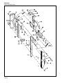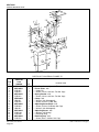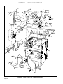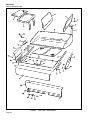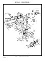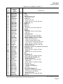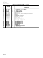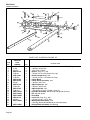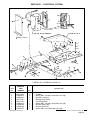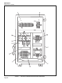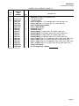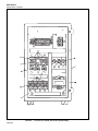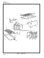
1
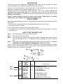
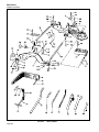
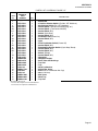
REPAIR PARTS CATALOG FOR
SUNNEN® POWER STROKED
PRECISION HONING MACHINE
MODEL:
MBC-1805
THIS CATALOG COVERS THE
ABOVE MODEL BEGINNING
WITH SERIAL NO. 96110.
“SUNNEN AND THE SUNNEN LOGO ARE REGISTERED TRADEMARKS OF SUNNEN® PRODUCTS COMPANY.”
SUNNEN® PRODUCTS COMPANY
7910 MANCHESTER AVENUE • ST. LOUIS, MO 63143, U.S.A. • PHONE: 314-781-2100
X-MBC-5046
Like any machinery, this equipment may
be dangerous if used improperly. Be
sure to read and follow instructions for
operation of equipment.
INTRODUCTION
Illustrations show all major components in exploded detail. Item numbers on each illustration are keyed to
the corresponding parts list, providing a descriptive identification of each part.
The parts lists include assemblies as well as detail parts. An item listed without a part number can be
obtained as a component of the complete assembly of which it is a part.
Standard hardware items are listed with complete descriptions, such as Item 29 below. These may be
purchased at your local hardware store, but it is important to replace an item with one having the same
dimensions as the original. In some places brand names and part numbers are shown. These may change
depending upon availability.
Sunnen® Products Company reserves the right to make changes, without notice, to materials,
specifications, colors, designs and accessories included with units.
HOW TO ORDER
When ordering replacement parts be sure to include the following information to ensure prompt shipment of
correct parts:
1. The part number and description of each part desired, obtained from this parts catalog.
2. The quantity of each part desired.
3. The voltage, frequency and phase, when ordering electrical parts.
4. The model and serial number of the machine, obtained from the name plate, where there is any question
concerning a part.
HOW TO USE THIS PARTS LIST
Step 1. – Locate desired part on illustration. Note item number.
Step 2. – Locate item number in the parts list.
Step 3. – If the item has a part number listed, order by part number and the description. A part number in
light face type indicates that it is a component of the last preceding part number in bold face
type.
Step 4. – If no number is listed, order the part number of the unit of which the desired part is a component.
ORDER ONLY BY PART NUMBER AND DESCRIPTION – NOT by item number.
NOTE: In this manual, parts may be followed by “(For CE Machines)” or “(For Non-CE Machines)” to denote
domestic machines from exported machines. The CE version is constructed to meet the requirements of the
European market, and is available to any customer.
1
Step 1.
4
2
3
15
17
14
Step 2.
Step 3.
Step 4.
ITEM
NO.
ORDER BY
PART
NUMBER
QTY.
1
2
3
4
MVH-4499A
PHSM-405
PHW-354
MVH-4422
1
3
3
1
....Spindle Cap includes
......Screw (M6 x 1 x 16 SHCS)
......Washer (M6)
....Inner Spindle Nose
14
15
16
17
PEM-870A
PEM-871
PEM-872
PHSM-600
1
1
1
1
....Cable Carrier includes
......Cable Carrier Bracket
......Cable Carrier Bracket
....Screw (M3 x 0,5 x 5mm FHCS)
iii
DESCRIPTION
GENERAL INFORMATION
The Sunnen® equipment has been designed and engineered for a wide variety of parts within the capacity and limitation of the equipment. With proper care
and maintenance this equipment will give years of service.
READ THE FOLLOWING INSTRUCTIONS CAREFULLY AND THOROUGHLY BEFORE UNPACKING, INSPECTING, OR INSTALLING THIS
EQUIPMENT.
IMPORTANT: Read any supplemental instructions BEFORE installing this equipment. These supplemental instructions give you important information to
assist you with the planning and installation of your SUNNEN® equipment.
Sunnen Technical Service Department is available to provide telephone assistance for installation, programming, & troubleshooting of your Sunnen
equipment. All support is available during normal business hours, 8:00 AM to 4:30 PM Central Time.
Review all literature provided with your Sunnen equipment. This literature provides valuable information for proper installation, operation, and maintenance
of your equipment. Troubleshooting information can also be found within the Instructions. If you cannot find what you need, call for technical support.
Where applicable, programming information for your Sunnen equipment is also included. Most answers can be found in the literature packaged with your
equipment.
Help us help you. When ordering parts, requesting information, or technical assistance about your equipment, please have the following
information available:
• Have ALL MANUALS on hand. The Customer Services Representative or Technician will refer to it.
• Have Model Number and Serial Number printed on your equipment Specification Nameplate.
• Where Applicable: Have Drive model and all nameplate data. Motor type, brand, and all nameplate data.
For Troubleshooting, additional information may be required:
• Power distribution information (type - delta, wye, power factor correction; other major switching devices used, voltage fluctuations)
• Installation Wiring (separation of power & control wire; wire type/class used, distance between drive and motor, grounding).
• Use of any optional devices/equipment between the Drive & motor (output chokes, etc.).
For fast service on your orders call:
Sunnen Automotive Customer Service toll free at: 1-800-772-2878
Sunnen Industrial Customer Service toll free at: 1-800-325-3670
Customers outside the USA, contact your local authorized Sunnen Distributor.
Additional information available at: http://www.sunnen.com or e-mail: [email protected]
NOTE: Sunnen reserves the right to change or revise specifications and product design in connection with any feature of our products contained herein.
Such changes do not entitle the buyer to corresponding changes, improvements, additions, or replacements for equipment, supplies or accessories
previously sold. Information contained herein is considered to be accurate based on available information at the time of printing. Should any discrepancy of
information arise, Sunnen recommends that user verify the discrepancy with Sunnen before proceeding.
ESD PREVENTION REVIEW
Let's review the basics of a sound static control system and its effective implementation. First, in the three step plan:
1.
Always ground yourself when handling sensitive components or assemblies.
2.
Always use a conductive or shielded container during storage or transportation. These materials create a Faraday
cage which will isolate the contents from static charges.
3.
Open ESD safe containers only at a static safe work station.
At the static safe work station, follow these procedures before beginning any work:
A.
Put on your wrist strap or foot grounding devices.
B.
Check all grounding cords to make sure they are properly connected to ground, ensuring the effective dissipation of static charges.
C.
Make sure that your work surface is clean and clear of unnecessary materials, particularly common plastics.
D.
Anti-static bubble wrap has been included for use at the machine when an ESD safe workstation is not available.
You are now properly grounded and ready to begin work. Following these few simple rules and using a little common sense will go a long
way toward helping you and your company in the battle against the hazards of static electricity. When you are working with ESD sensitive devices, make sure you:
GROUND
ISOLATE
NEUTRALIZE
iv
SUNNEN® LIMITED PRODUCT WARRANTY
SUNNEN® Products Company and its subsidiaries (SPC) warrant that all new SPC honing machines, gaging equipment, tooling, and related equipment will
be free of defects in material and/or workmanship for a period of one year from the date of original shipment from SPC.
Upon prompt notification of a defect during the one-year period, SPC will repair, replace, or refund the purchase price, with respect to parts that prove to be
defective (as defined above). Any equipment or tooling which is found to be defective from improper use will be returned at the customer's cost or repaired
(if possible) at customer's request. Customer shall be charged current rates for all such repair.
Prior to returning any SPC product, an authorization (RMA#) and shipping instructions must be obtained from the Customer Service Department or items
sent to SPC will be returned to the customer.
Warranty Limitations and Exclusions This Warranty does not apply to the following:
• Normal maintenance items subject to wear and tear: (belts, fuses, filters, etc).
• Damages resulting from but not limited to:
› Shipment to the customer (for items delivered to customer or customer's agent F.O.B., Shipping Point)
› Incorrect installation including improper lifting, dropping and/or placement
› Incorrect electric power (beyond +/- 10% of rated voltage) including intermittent or random voltage spikes or drops
› Incorrect air supply volume and/or pressure and/or contaminated air supply
› Electromagnetic or radio frequency interference from surrounding equipment (EMI, RFI)
› Storm, lightning, flood or fire damage
› Failure to perform regular maintenance as outlined in SPC manuals
› Improper machine setup or operation causing a crash to occur
› Misapplication of the equipment
› Use of non-SPC machines, tooling, abrasive, fixturing, coolant, repair parts, or filtration
› Incorrect software installation and/or misuse
› Non-authorized customer installed electronics and/or software
› Customer modifications to SPC software
THE LIMITED WARRANTY DESCRIBED HEREIN IS EXPRESSLY IN LIEU OF ALL ANY OTHER WARRANTIES. SPC MAKES NO REPRESENTATION OR WARRANTY OF
ANY OTHER KIND, EXPRESS OR IMPLIED, WHETHER AS TO MERCHANTABILITY, FITNESS FOR A PARTICULAR PURPOSE OR ANY OTHER MATTER. SPC IS NOT
RESPONSIBLE FOR THE IMPROPER USE OF ANY OF ITS PRODUCTS. SPC SHALL NOT BE LIABLE FOR DIRECT, INDIRECT, INCIDENTAL, OR CONSEQUENTIAL
DAMAGES INCLUDING BUT NOT LIMITED TO: LOSS OF USE, REVENUE, OR PROFIT. SPC ASSUMES NO LIABILITY FOR PURCHASED ITEMS PRODUCED BY OTHER
MANUFACTURERS WHO EXTEND SEPARATE WARRANTIES. REGARDLESS OF ANY RIGHTS AFFORDED BY LAW TO BUYER, SPC's LIABILITY, IF ANY, FOR ANY AND
ALL CLAIMS FOR LOSS OR DAMAGES WITH RESPECT TO THE PRODUCTS, AND BUYER'S SOLE AND EXCLUSIVE REMEDY THEREFORE, SHALL IN ALL EVENTS BE
LIMITED IN AMOUNT TO THE PURCHASE PRICE OF THAT PORTION OF THE PRODUCTS WITH RESPECT TO WHICH A VALID CLAIM IS MADE.
Shipping Damages
Except in the case of F.O.B., Buyer's destination shipments, SPC will not be liable for any settlement claims for obvious and/or concealed shipping damages.
The customer bears the responsibility to unpack all shipments immediately and inspect for damage. When obvious and/or concealed damage is found, the
customer must immediately notify the carrier's agent to make an inspection and file a claim. The customer should retain the shipping container and packing
material.
SUNNEN® SOFTWARE LICENSE AGREEMENT
This document is a Legal Agreement between you, as user and licensee (Licensee), and Sunnen® Products Company (SPC) with respect to preprogrammed
software (Software) provided by SPC for use on SPC Equipment. By using the Software, you, as Licensee, agree to become bound by the terms of this
Agreement.
In consideration of payment of the license fee (License Fee) which is part of the price evidenced by your receipt (Receipt), SPC grants to you as Licensee
a non-exclusive right, without right to sub-license, to use the particular copy of the SPC Software licensed hereunder only on the particular equipment sold with
the Software. SPC reserves all rights including rights not otherwise expressly granted, and retain title and ownership to the Software including all subsequent copies or updates in any media. The Software and all accompanying written materials are covered by copyrights owned by SPC. If supplied on
removable media (floppy disk), you, as Licensee, may copy the Software only for back up purposes; or you may request that SPC copy the Software for you
for the same purposes. All other copying of the Software or of the accompanying written materials is expressly forbidden and is in violation of the Agreement.
The Software and accompanying written materials (including the user's manual, if any) are provided in an "as is" condition without warranty of any kind
including the implied warranties of merchantability and fitness for a particular purpose, even if SPC has been advised of this purpose. SPC specifically does
not warrant that it will be liable as a result of the operation of the Software for any direct, indirect, consequential or accidental damages arising out of the
use of or inability to use such product even if SPC has been advised of the possibility of such use. It is recognized that some states do not allow the exclusion or limitation of liability for consequential or accidental damages and to the extent this is true, the above limitations may not apply.
Any alteration or reverse engineering of the software is expressly forbidden and is in violation of this agreement.
SPC reserves the right to update the software covered by this agreement at any time without prior notice and any such updates are covered by this
agreement.
v
SAFETY INSTRUCTIONS
READ FIRST
This machine, like any equipment, may be dangerous if used improperly. Please
read all warnings and instructions before attempting to use this machine.
Always disconnect power at main enclosure before servicing machine.1
Always wear eye protection when operating this machine.
NEVER open or remove any machine cover or protective guard with power "ON."
Always disconnect power at main enclosure before servicing this equipment.1
DO NOT attempt any repair or maintenance procedure beyond those described in
this book. Contact your Sunnen® Field Service Engineer or Technical Services
Representative for repairs not covered in these instructions.
Due to the wide variety of machine configurations, all possibilities cannot be
described in these instructions. Instructions for safe use and maintenance of
optional equipment ordered through Sunnen, will be provided through separate
documentation and/or training provided by your Sunnen Field Service Engineer or
Technical Services Representative.
DO NOT attempt to defeat any safety device on this machine or on any of the
optional equipment.
If specially built automation components are added to this system, be sure that
safety is not compromised. If necessary, obtain special enlarged work area safety
system from Sunnen Products Co.
Indicates CE version ONLY.
1
DO NOT touch electrical components until main input power has been turned off and CHARGE
lamps are extinguished. WARNING: The capacitors are still charged and can be quite dangerous.
vi
CONTENTS
PAGE
Introduction ..........................................................................................................
How To Order ......................................................................................................
How To Use This Parts List .................................................................................
General Information .............................................................................................
ESD Prevention Review ......................................................................................
Limited Product Warranty ....................................................................................
Sunnen Software License Agreement ..................................................................
General Safety Instructions ..................................................................................
Contents ...............................................................................................................
iii
iii
iii
iv
iv
v
v
vi
1
HONING MACHINE HEAD
A Honing Machine Head & Motor Assembly ..........................................................
B Honing Machine Head Assembly ........................................................................
C Automatic Shutoff ................................................................................................
D Stone Saver Assembly ........................................................................................
2
5
8
10
HONING MACHINE BASE
E Base, Filter, Pump & Coolant Assembly .............................................................
F Air Actuated Pedal Depressor .............................................................................
G Coolant Reservoir Unit ........................................................................................
H Foot Pedal Unit ....................................................................................................
I Drip Tray & Accessories ......................................................................................
12
16
19
20
22
POWER STROKER
J Power Stroking Attachment .................................................................................
K Arm Assembly .....................................................................................................
L Tube & Shaft Assembly .......................................................................................
M Cross Arm Assembly ...........................................................................................
24
28
31
32
ELECTRICAL SYSTEM
N Automatic Size Control ........................................................................................
O Electrical Control Enclosure (For Non “CE” Machines) .......................................
P Electrical Control Enclosure (For Non “CE” Machines).......................................
Q Electrical Control Enclosure (For “CE” Machines) ..............................................
R Control Box ..........................................................................................................
33
35
36
38
40
COVERS & GUARDS
S Sheet Metal Covers & Latches ............................................................................ 42
T Belt Guard Assembly ........................................................................................... 44
U Work Area Cover ................................................................................................. 46
“SUNNEN AND THE SUNNEN LOGO ARE REGISTERED TRADEMARKS OF SUNNEN® PRODUCTS COMPANY.”
© Copyright 2004 by Sunnen® Products Company • Printed in U.S.A.
Page 1
SECTION I - HONING MACHINE HEAD
FIGURE A - HONING MACHINE HEAD & MOTOR ASSEMBLY
Page 2
SECTION I
HONING MACHINE HEAD
PARTS LIST COVERING FIGURE “A”
ITEM
NO.
1
1
1
2
3
4
5C
6
6A
6B
6A
7
7A
8
8A
9
10
11
12
13
14
14A
15
16
17
18
19
N/S
20
21
22
23
24
25
N/S
26
27
28
29
30
31
32
33
34
35
36
37
38
38A
ORDER BY
PART
NUMBER
QTY.
PMO–580A
PMO–579A
PMO–580H
KN-567
KN-568
PEC-103
MBB–2606A
MBB–1826A
LBN-340
MBB–1846A
LBN-340
MBB–1830A
MBB-1833A
MBB–1815A
MBB–1835A
MBB–1840A
MBB–1850A
MBB–1870A
UN-18
PHW-120
PHS-686
MBB–1855A
KN-523
MBB–1867A
PHS-637
MBB–1860A
KN-568
LBB-891
PHW-119
MBB–1874A
DL-36
MBB–968A
LBN-431
MBB–978A
MBB-977
PHN-121
MBB-973C
PHS-630
MBB-972
MBB-1821
MBB-1823A
MSN-277
MBH-396
MBB-985A
MBB-976A
MBB-2441A
MAN-1223
PHS-605
PBR-57A
PHS-128
1
1
1
4
4
1
1
1
2
1
2
1
1
1
1
1
1
1
1
1
1
1
2
1
1
1
1
1
1
1
1
1
1
1
1
1
1
1
2
1
1
1
1
1
1
1
1
1
1
1
DESCRIPTION
....*Motor (1HP, 208/230/460V, 60Hz, 3Ph, 1745 RPM, 7/8 Dia. Shaft)
....*Motor (1HP, 380/400V, 50Hz, 3Ph, 1450 RPM, 7/8 Dia. Shaft)
....*Motor (1HP, 220/440V, 50Hz, 3Ph, 1450 RPM, 7/8 Dia. Shaft)
....Screw (5/16–18 x 1 Hex Hd. Cap)
....Washer (5/16 Plain)
....Connector includes 4A and 5
....Guard
....Motor Pulley (60 Hz Machines) with
......Set Screw (1/4–20 x 3/8 Soc. Cup Pt.)
....Motor Pulley (50 Hz Machines) with
......Set Screw (1/4–20 x 3/8 Soc. Cup Pt.)
....“V” Belt (60 Hz Machines)
....“V” Belt (50 Hz Machines)
....Countershaft Pulley (60 Hz Machines) with Bearing
....Countershaft Pulley (50 Hz Machines) with Bearing
....“V” Belt
....Idler Assembly includes
........Idler Release Assembly with
........Washer (5/16 Fiber)
........Spring Washer
........Shoulder Screw (5/16 x 3/8 with 1/4–20 x 7/16 Thd.)
......Idler Arm with
........Set Screw (5/16–18 x 1/2 Soc. Plain Cup Pt.)
......Shoulder Bushing with
........Screw (5/16–18 x 1–1/4 Soc. Flat Hd. Cap)
......Idler Pulley Assembly with
........Washer (5/16 Plain)
........Screw (5/16–18 x 3/4 Soc. Hd. Cap)
........Washer (5/16 Lock)
....Stud with
......Nut (3/8–16 Hex)
....Brake Adjusting Screw with
......Nut (1/4–20 Hex)
....Brake Lever with
........Shoulder Screw (5/16 x 5/8 with 1/4-20 x 7/16 Thd.)
........Locknut (1/4-20 Hex)
....Brake Cam with
......Screw (5/16-18 x 1-1/4 Soc. Hd. Cap)
......Washer (5/16 Serrated Lock)
......Spacer
....Brake Strap with
......Screw (10-32 x 3/8 Rd. Hd.)
......Washer (Bent)
....Brake Rod Assembly with
......Retaining Ring
....Brake Anchor with
......Washer (3/8 Lock)
......Screw (3/8-16 x 1 Soc Hd. Cap)
....Bearing
....Set Screw (10-32 x 1/4 Soc. Nylon Tip)
N/S indicates Not Shown
*Specify brand name of motor, voltage and hertz if other than as listed.
(Parts continued on next page)
Page 3
SECTION I
HONING MACHINE HEAD
PARTS LIST COVERING FIGURE “A” (cont’d)
ITEM
NO.
ORDER BY
PART
NUMBER
QTY.
39
40
41
42
43
44
45
46
47
48
52
53
54
55
56
57
58
42
43
44
-59
60
61A
61
61B
61C
61D
62
63
65
67
67A
67B
68
69
70
71
71A
71B
71C
72
72A
73
74
74A
75
76
77
MBB-2529A
MBB-1807A
MBB-365A
MBB-646
MBB-647
MBB-359A
LBN-385A
LBN-386
KN-172
MB-3089A
MBB-3491A
MBB-2498A
PBR-147A
MBB-2497A
PHS-582
MBB-3495A
MBH-649A
MBB-646
MBB-647
MBB-359A
MBC-345A
MBC-346A
MBB-642A
MBB-332A
MBC-353A
PHS-165A
MBC-354A
PHS-164A
MBC-347A
AG-128A
PNP-329A
MBB-2320
MAN-1223
KN-416
MBB-2563A
MAN-612
PNP-328A
PHM-306A
PHW-119
KN-567
PHS-775
KKN-943A
PHM-728A
MBB-2528A
PHS-506
LBA-451
LBN-462A
LN-570A
MBC-356A
1
1
1
1
1
1
2
4
4
1
1
1
1
1
4
1
1
1
1
1
1
1
1
1
4
1
4
1
1
2
1
1
4
4
1
1
1
1
1
1
1
1
1
1
4
4
1
1
1
N/S indicates Not Shown
Page 4
DESCRIPTION
....Spacer
....Spindle Pulley
....Thrust Assembly with
......Screw (3/8-16 x 3/4 Soc. Hd. Cap)
......Washer (3/8)
......Washer (.555 Special)
....Feed Arm Assembly (Pkg. of 2) with
......Screw (5/16-18 x 1/2 Hex Hd. Cap)
......Nut (5/16-18 Hex)
....Feed Arm Stabilizer with Attaching Hardware
....Bearing Spacer
....Bearing Sleeve
....Bearing with Snap Ring
....Bearing Retainer with
......Screw (1/4-20 x 3/4 Soc. Hd. Cap)
....Spindle
....Feed Rod Assembly with
......Screw (3/8-16 x 3/4 Soc. Hd. Cap)
......Washer (3/8 Special)
......Washer (.555 Special)
....Adjustable Spindle Nose Complete includes
......Spindle Nose Shell
......Drive Plate with
........Set Screw (1/4-20 x 3/8 Soc. Full Dog Pt.)
......Set Screw (5/16-24 x 5/8 Soc. Flat Pt.) (Pkg. of 4)
......Set Screw (1/2-20 x 1/2 Soc. Flat Pt.)
......Set Screw (5/16-40 x .480 Soc. Ground Flat Pt.) (Pkg. of 4)
......Set Screw (1/4-20 x 1/2 Soc. Full Dog Pt. / Nylok)
......Adjustable Nose
......Screw (1/4-20 x 3/4 Soc. Hd. Cap) (Pkg. of 2)
....Heavy Pressure Dial Overlay
....Housing
....Washer (3/8 Plain)
....Screw (3/8-16 x 1-1/4 Hex Hd. Cap)
....Dial Pointer with
......Screw (1/4-20 x 3/8 Hex Hd. Cap)
....Feed Dial Overlay
....Belt Cover Latch Pin with
......Washer (5/16 Lock)
......Screw (5/16-18 x 3/4 Hex Hd. Cap)
......Screw (5/16-18 Lock)
....Top Cover
....Grommet
....Cover with
......Screw (10-32 x 1/4 Button Hd. Cap)
......Washer
....Mandrel Wrench
....Concentric Sleeve - Optional (Not Supplied with Machine)
....Spindle Nose Cover
SECTION I
HONING MACHINE HEAD
S E E F IG . N
FIGURE B - HONING MACHINE HEAD ASSEMBLY
PARTS LIST COVERING FIGURE “B”
ITEM
NO.
ORDER BY
PART
NUMBER
QTY.
1
2
3
4
5
6
7
8
9
MBB-2485A
EL-11
LBA-437
LBN-450C
LBN-369
LBA-150
LBA-445A
MB-908
LBA-456A
1
1
1
1
1
2
1
1
1
N/S indicates Not Shown
DESCRIPTION
....Pressure Dial Assembly, Upper with
......Spring
......Plate
......Set Collar with
........Set Screw (1/4-20 x 1/4 Soc. Cup Pt.)
......Nut (3/8-24 Hex)
......Spherical Socket with
........Spherical Washer
......Thread Nut with
(Parts continued on next page)
Page 5
SECTION I
HONING MACHINE HEAD
PARTS LIST COVERING FIGURE “B” (cont’d)
ITEM
NO.
ORDER BY
PART
NUMBER
QTY.
9A
10
11
12
2
3
4
5
6
13
14
7
8
9
9A
10
11
15
16
17
18
19
20
21
22
23
24
25
26
27
28
29
30
31
32
33
34
35
36
37
38
39
40
41
42
43
44
45
46
47
48
49
50
51
52
53
54
PHN-147
LBA-438C
MSA-63
MBB-2475A
EL-11
LBA-437
LBN-450C
LBN-369
LBA-150
MSA-151
LBA-453A
LBA-445A
MB-908
LBA-456A
PHN-147
LBA-438C
MSA-63
MBB-2525A
MBB-938
MSN-345
MBB-946A
MBB-939
MBB-947C
MBB-2487A
PHW-118
LBN-431
MBB-885A
PBR-54A
PBR-34A
MBB-2920A
MBB-866A
PHS-106
MBB-858
MBB-859
MBB-867A
MBB-1897A
MBB-312
LBA-381A
LBA-367C
PBR-53A
MBB-1859A
MBB-1858A
LBN-337A
KN-456
MBB-2912A
LBN-485
PSP-303A
LBA-446A
MBB-2915A
PHS-612
PHW-145A
MBB-2464A
MBB-2460A
CK-3187
LBN-408
LBA-395A
LBN-406A
1
1
1
1
1
1
1
1
2
1
1
1
1
1
1
1
1
1
1
1
1
1
1
1
1
1
1
1
2
1
1
1
1
1
3
1
1
1
1
2
1
2
1
1
1
1
1
1
1
1
1
1
1
1
1
1
1
N/S indicates Not Shown
Page 6
DESCRIPTION
........Jam Nut (3/8-24 Hex)
......Pin with
........Nut (10-32 Hex)
....Pressure Dial Assembly, Lower with
......Spring
......Plate
......Set Collar with
........Set Screw (1/4-20 x 1/4 Soc. Cup Pt.)
......Nut (3/8-24 Hex)
......Washer (3/8 Hardened)
......Spring
......Spherical Socket with
........Spherical Washer
......Thread Nut with
........Jam Nut (3/8-24 Hex)
......Pin with
........Nut (10-32 Hex)
....Pressure Rod Assembly with
......Spring Collar
......Set Screw (5/16-18 x 5/16 Soc. Cup Pt.)
......Spring with
........Washer (Special)
....Lever with
......Lever Pivot with
........Washer (1/4 Lock)
........Nut (1/4-20 Hex)
....Spring Support Assembly
....Bearing
....Bearing (Pkg. of 2)
....Arm & Shaft Assembly with
......Set Collar with
........Set Screw (1/4-28 x 5/16 Soc. Cup Pt.)
........Washer (Special)
........Sping Washer
........Thrust Bearing, Nylon (Pkg. of 3)
......Spacer
......Set Screw (3/8-16 x 1/2 Soc. Cup Pt.)
....Adjusting Nut Assembly
....Sleeve
....Bearing (Pkg. of 2)
....Idler Shaft
....Thrust Bearing (Pkg. of 1)
....Set Collar with
......Set Screw (1/4-20 x 3/8 Soc. Cup Pt.)
....Idler Tension Arm with
......Set Screw (3/8-16 x 5/8 Soc. Cup Pt.)
....Spring
....Lever
....Crank Arm Lever with
......Screw (1/4-28 x 3/4 Soc. Flat Hd. Cap)
......Washer (Spring)
....Bearing Insert
....Stub Crank Arm Assembly with
......Washer (1/4 Plain)
......Cotter Pin (1/16 x 1/2 Long)
....Feed Arm Link Assembly
....Stop Pin with
(Parts continued on next page)
SECTION I
HONING MACHINE HEAD
PARTS LIST COVERING FIGURE “B” (cont’d)
ITEM
NO.
55
56
57
59
60
58
61
58
62
63
64
65
66
67
68
69
70
71
72
73
74
68
75
76
77
78
79
80
81
82
83
84
85
86
87
88
90
91
92
93
94
95
96
97
97A
99
100
N/S
101
98
102
103
104
105
106
107
108
ORDER BY
PART
NUMBER
QTY.
KN-568
LBN-408
MBB-2405A
MBB-986A
LBN-369
LBN-379
PSP-105A
LBN-379
LBN-372A
LBN-369
MBB-719A
MBB-2895A
MBB-718A
MBB-716
PG-587
PHS-122
PHS-583
KKN-1116A
PHS-579
KKN-1110A
PHR-326
PG-587
PHW-132
KKN-1114A
PG-505
PG-984
KKN-1120A
PHS-120
KKN-1139A
MSN-277
MBB-707A
MBB-708TA
MBB-709TA
MBB-705A
MBB-2320
--MSN-189
PHS-584
KKN-1165A
KKN-1169
PHW-119
LBB-891
KKN-1171
LBS-451
AG-178
KKN-1155A
KKN-1161
POR-107A
KKN-1163A
PHS-532
ASC-377A
ASC-378
PHS-532
ASC-358A
--PHS-582A
PHW-118
1
1
1
1
1
1
1
2
1
1
1
1
2
1
2
1
1
1
1
1
1
2
1
1
2
2
1
2
1
1
1
1
1
1
1
1
1
1
1
2
2
2
1
1
1
1
1
1
1
2
1
1
1
1
1
2
2
DESCRIPTION
......Washer (5/16 Plain)
......Nut (5/16-18 Hex)
....Feed Screw with
......Set Collar with
........Set Screw (1/4-20 x 1/4 Soc. Cup Pt.)
......Fiber Washer
....Spring with
......Fiber Washer
....Dial Assembly with
......Set Screw (1/4-20 x 1/4 Soc. Cup Pt.)
....Plate
....Body Assembly with
......Spring (Pkg. of 3)
......Rocker
......Washer
......Set Screw (1/4-20 x 1/2 Soc. Flat Pt.)
......Screw (1/4-20 x 1 Soc. Hd. Cap)
....Follower Spring Stop with
......Screw (10-32 x 1-1/4 Soc. Hd. Cap)
....Follower Block Assembly with
......Retaining Ring
......Washer
......Spring Washer
......Follower Spring Set (2 Pieces) with
........Washer
........Screw (4-40 x 5/16 Self Tapping Binding Hd.)
....Trigger Assembly with
......Set Screw (8-32 x 1/2 Soc. Oval Pt.)
....Spindle Nose Cover Clip with
......Screw (10-32 x 3/8 Rd. Hd.)
....Dial Indicator & Pin Assembly includes
....Dial Indicator Bezel & Crystal
......Dial Indicator Face
......Cushion Indicator Tip
....Housing
....Automatic Shutoff (See Fig. “C”)
......Washer (1/4 Plain)
......Screw (1/4-20 x 1-1/2 Soc. Hd. Cap)
....Base Assembly with
......Spacer Washer
......Washer (5/16 Lock)
......Screw (5/16-18 x 3/4 Soc. Hd. Cap)
......Cover
......Washer
......Screw (10-32 x 3/8 Soc. Hd. Cap)
....Piston Assembly with
......Cylinder
......“O” Ring
....Pivot Cross Pin with
......Screw (10-32 x 1/4 Button Hd. Cap)
....Cable Pull with
......Bushing
......Screw (10-32 x 1/4 Button Hd. Cap)
....Cable Kit
....Stone Saver Assembly (See Fig. “D”)
....Screw (1/4-20 x 3/4 Soc. Hd. Cap) (Pkg. of 2) with
......Washer (1/4 Lock)
N/S indicates Not Shown
Page 7
SECTION I
HONING MACHINE HEAD
FIGURE C - AUTOMATIC SHUTOFF
Page 8
SECTION I
HONING MACHINE HEAD
PARTS LIST COVERING FIGURE “C”
ITEM
NO.
ORDER BY
PART
NUMBER
QTY.
1
2
3
4
5
6
7
8
9
10
11
12
15
16
17
18
19
20
21
22
23
24
28
25
29
30
31
32
33
34
-35
35A
36
37
-38
39
40
41
42
-43
44
45
46
47
48
KKN-964A
PHS-506
PHS-580
PNP-333A
PHS-584
MSN-189
KKN-2041A
KKN-1079A
PHS-751
PHS-579
PG-587
KKN-1069A
KKN-1068A
KKN-1062A
PHR-307
KKN-1078A
KKN-1061A
KKN-1064A
KKN-1019A
LBN-309
LN-1656
KKN-1021A
PHS-506
PSP-304A
PHS-594A
KKN-1024A
KKN-1015A
PHS-611
KKN-1022A
PHS-626
KKN-1050A
KKN-1030A
PSP-312A
PHS-603
KKN-1059A
KKN-1055A
KKN-1056
LN-78
KKN-1057A
MSA-63
KKN-1025A
KKN-1040A
KKN-1035A
KKN-1045A
PG-587
PG-2252
PSP-301A
KKN-1080A
1
3
1
1
1
1
1
1
2
1
1
1
1
1
1
1
1
1
1
1
2
1
3
1
1
1
1
1
1
1
1
1
1
1
1
1
1
1
1
1
1
1
1
1
1
1
1
1
DESCRIPTION
....Cover with
......Screw (10-32 x 3/8 Button Hd. Cap)
......Screw (1/4-28 x 3/8 Button Hd. Cap)
......Instruction Label
....Screw (1/4-20 x 1-1/2 Soc. Hd. Cap)
....Washer (1/4 Plain)
....Manual Trip Lever with
......Lock Out Spring with
........Screw (4-40 x 1/4 Self Tapping Binding Hd.)
......Screw (10-32 x 1-1/4 Soc Hd. Cap)
......Washer
......Manual Trip Pivot
....Retaining Plate
....Switch Box Spacer with
......Retaining Ring
....Spring
....Guide Rail
....Spacer
....Lower Mount with
......Set Screw (1/4-20 x 1/2 Soc. Cup Pt.)
......Screw (10-32 x 5/8 Soc. Flat Hd. Cap)
....Front Bar with
......Screw (10-32 x 3/8 Button Hd. Cap)
....Spring
....Shoulder Screw (5/16 x 1/4 with 1/4-20 x 7/16 Thd.)
....Lockout Screw
....Base
....Screw (1/4-20 x 5/8 But. Hd. Cap)
....Main Bearing Shaft with
......Screw (1/4-28 x 11/16 Flat Hd. Soc. Cap)
....Toggle Set includes
......Toggle Link Assembly, Lower with
........Spring
......Screw (10-32 x 3/4 Button Hd. Cap)
......Inner Race
......Toggle Link Assembly, Outer includes
........Toggle Link, Outer
........Groove Pin
........Cam Screw
........Nut (10-32 Hex)
......Toggle Link Assembly, Inner
....Auto Trip Assembly includes
......Auto Trip Lever Assembly
......Trip Catch Assembly
......Washer
......Retaining Ring
......Spring
....Cocking Lever
N/S indicates Not Shown
Page 9
SECTION I
HONING MACHINE HEAD
FIGURE D - STONE SAVER ASSEMBLY
PARTS LIST COVERING FIGURE “D”
ITEM
NO.
1
3
4
5
6
5
7
8
9
10
11
12
13
14
15
16
17
ORDER BY
PART
NUMBER
KKN-860A
KKN-895A
PHP-567
PHS-612
KKN-924A
PHS-612
PEM-336A
LBA-451
PHS-552
KKN-889A
PHS-683
LBA-451
KKN-893A
PHW-163
PHR-308
KKN-894A
PHS-578
N/S indicates Not Shown
Page 10
QTY.
1
1
1
1
1
1
1
1
1
1
2
2
1
1
1
1
2
DESCRIPTION
....Sub Base Assembly with Threaded Inserts
....Piston Pivot with
......Groov-Pin
......Screw (1/4-28 x 3/4 Soc. Flat Hd. Cap)
....Spring Anchor with
......Screw (1/4-28 x 3/4 Soc. Flat Hd. Cap)
....Clamp with
......Washer (#10 Shakeproof)
......Screw (10-32 x 1/2 Rd. Hd.)
....Adjusting Screw Block with
......Screw (10-32 x 5/8 Button Hd. Cap)
......Washer (#10 Shakeproof)
....Adjusting Screw with
......Washer (1/4 Spring)
......Retaining Ring
....Retaining Cap with
......Screw (6-32 x 3/8 Soc. Hd. Cap)
(Parts continued on next page)
SECTION I
HONING MACHINE HEAD
PARTS LIST COVERING FIGURE “D” (cont’d)
ITEM
NO.
18
19
20
21
22
19
20
21
23
24
25
26
27
28
29
30
31
33
34
36
37
38
39
40
41
42
43
44
45
46
48
47
49
50
51
52
53
54
55
56
57
58
59
60
61
62
63
64
65
ORDER BY
PART
NUMBER
KKN-887A
PG-587
LBA-451
PHS-506
KKN-886A
PG-587
LBA-451
PHS-506
KKN-872A
PHR-307
TN-54
KKN-871A
KKN-883A
AG-438D
KKN-882A
PHS-713
KKN-875A
PHR-307A
KKN-915A
CRG-939A
KKN-912A
PSP-307A
KKN-905A
KKN-909A
PHR-305A
KKN-927A
PHW-171
MBB-982
KKN-929A
KKN-930A
LN-1545
KKN-908A
KKN-949A
LN-1545
KKN-944A
PG-587A
PHN-134A
KKN-918A
MSN-177C
KKN-920A
PHR-302
KKN-935A
PHM-727A
PHN-117
KKN-952A
PHS-506
LBA-451
PNP-332A
KKN-953A
QTY.
1
2
2
2
1
2
2
2
1
1
1
1
1
16
1
2
1
1
1
1
1
1
1
1
1
1
4
3
1
1
1
1
1
1
1
1
1
1
1
1
1
1
1
1
1
4
4
1
1
DESCRIPTION
....Top Clamp with
......Washer (#10 Plain)
.....Washer (#10 Shakeproof)
......Screw (10-32 x 3/8 Button Hd. Cap)
....Bottom Clamp with
......Washer (#10 Plain)
......Washer (#10 Shakeproof)
......Screw (10-32 x 3/8 Button Hd. Cap)
....Cam with
......Retaining Ring
......Spring Washer
....Cross Slide
....Ball Carrier with
......Gage Ball (Pkg. of 16)
....End Plate with
......Screw (5-40 x 3/16 Soc. Hd. Cap)
....Fork & Rod with
......Retaining Ring
......Cylinder & Pin with
......“O” Ring
....Cylinder
....Spring
....Piston
....Piston Nut
....Retaining Ring
....Metering Screw
....Washer (1/4 Spring)
....Washer (1/4 Plain)
....Metering Stop
....Stop Collar & Pin with
......Set Screw (8-32 x 1/4 Soc. Cup Pt.)
....Spring Clip
....Metering Knob with
......Set Screw (8-32 x 1/4 Soc. Cup Pt.)
....Pointer with
......Washer (#10 Plain)
......Nut & Lockwasher
....Cam Lever with
......Screw (10-32 x 5/8 Soc. Hd. Cap)
....Pull Rod Pivot with
......Retaining Ring
....Pull Rod
....Stud Bumper with
......Nut & Lockwasher
....Cover with
.....Screw (10-32 x 3/8 Button Hd. Cap)
......Washer (#10 Shakeproof)
......Stonesaver Overlay
......Hole Plug
N/S indicates Not Shown
Page 11
SECTION II - HONING MACHINE BASE
FIGURE E - BASE, FILTER, PUMP, & COOLANT ASSEMBLY
Page 12
SECTION II
HONING MACHINE BASE
PARTS LIST COVERING FIGURE “E”
ITEM
NO.
1
1
1
2
3
4
2A
3
3A
4
2B
5
N/S
N/S
6
6A
6B
6C
6D
6E
N/S
N/S
N/S
7
7A
7B
7C
7D
7E
7F
7J
8
9
10
11
11A
12
13
14
15
16
16A
N/S
N/S
17
18
19
N/S
21
N/S
ORDER BY
PART
NUMBER
PMO-345A
PMO-347A
PMO-345H
PF-224A
PHW-119
KN-172
PF-224D
--PHW-119
KN-172
CH-371A
MB-3297A
KN-568
KN-172
PF-500A
PF-501
PHS-164A
PF-502A
PHW-119
LBN-386
PF-505A
PF-506A
PF-507A
PPP-147A
PPP-161A
PPP-171A
PF-171A
PPP-29A
PPP-22A
PPP-116A
PPP-169A
PPP-41A
PPP-207A
PPP-42A
PF-317A
PEM-315
PF-162C
MAN-1028
PHW-118
LBN-431
PF-240A
PF-243A
PF-244A
PF-247A
PF-246A
PF-260A
PF-270A
PF-105-4
PF-257A
PF-258A
N/S indicates Not Shown
QTY.
1
1
1
1
8
8
1
1
1
2
1
1
4
2
1
1
1
1
1
1
1
1
1
1
1
1
1
1
1
1
1
1
1
1
1
1
1
4
4
4
1
1
1
1
1
1
1
1
1
1
DESCRIPTION
....Motor (1/2 H.P., 208/230/460 Volt, 60 Hz, 3 Ph.)
....Motor (1/2 H.P., 380/400 Volt, 50 Hz, 3 Ph.)
....Motor (1/2 H.P., 220/440 Volt, 50 Hz, 3 Ph.)
....Flex Bolt Mounting Set with
......Washer (5/16 Plain)
Nut (5/16-18 Hex)
....Flex Bolt Mounting with
......Washer (5/16 Plain)
......Washer (5/16 Lock)
......Nut (5/16-18 Hex)
....Pump Bracket
....Motor Base with
......Washer (5/16 Plain)
......Nut (5/16-18 Hex)
....Pump with
......Collar
......Set Screw (1/4-20 x 1/2 Full Dog Point with insert)
....Bracket with
......Washer (5/16 Lock)
......Screw (5/16-18 x 1/2 Hex Hd. Cap)
....Mechanical Seal (PF-500A Pump)
....Bearing (PF-500A Pump)
....Gasket Set (PF-500A Pump)
....Close Nipple
....Adapter
....Side Outlet Elbow
....Relief Valve
....Hose Assembly
....Hose Assembly
....Adapter
....Street Elbow
....Hose Assembly
....Tee
....Hose
....Intake Strainer with
......Clamp
....Mounting Bracket with
......Screw (1/4-20 x 3/4 Hex Hd. Cap)
......Washer (1/4 Lock)
......Nut (1/4-20 Hex)
....Filter Container Assembly with
......Cover
......Gasket
......Spring
......Air Vent
......Clamp Assembly with
........Tee Handle Assembly
....Filter Element (Pkg. of 4)
....Standpipe with
......Washer (Fiber) (Pkg. of 2)
(Parts continued on next page)
Page 13
SECTION II
HONING MACHINE BASE
PARTS LIST COVERING FIGURE “E” (cont’d)
ITEM
NO.
22
23
24
25
26
27
28
29
30
31
32
33
33A
34
35
36
37
37A
38
39
N/S
40
41
42
43
44
45
N/S
46
47
48
49
50
51
52
53
54
55
60
61
62
63
65
64
65
66
67
68
69
70
ORDER BY
PART
NUMBER
QTY.
PF-259A
PPP-351
MB-2267A
CRG-404
MB-2165A
PHS-599
MB-2177A
MB-2184A
MB-2176A
MB-2182A
MBB-1630A
PPP-41A
PPP-27A
PEM-340
PPP-148A
PPP-533
PES-338A
PES-338-1A
MB-2185A
MB-2194A
PHN-116
MB-2193A
MB-2202A
MB-2203A
MB-2205A
KN-538
MB-2210A
PHP-101
P-144
LBA-451
MSA-63
PF-288A
PHSM-629
PHW-327
LBA-451
MB-2214A
MB-2299A
CRG-404
MB-2143A
MB-2135A
MB-2140A
MAN-1028
PHW-118
MB-2132A
PHW-118
MSA-219
KKN-1124A
MBB-977
PHN-121
MB-3095A
1
1
1
2
1
1
1
1
3
3
1
1
1
3
1
1
1
1
3
3
3
3
1
1
1
1
1
4
2
6
6
1
2
1
1
1
2
2
1
1
2
4
4
1
2
2
1
1
1
1
N/S indicates Not Shown
Page 14
DESCRIPTION
....Draincock
....Close Nipple (1/2 NPT Black Iron)
....Rear Splash Guard - Left with
......Screw (1/4-20 x 3/8 Rd.Hd.)
....Valve Body Assembly with
......Screw (1/4-20 x 2 Soc. Hd. Cap)
......Inlet Stem with
........“O” Ring
......Outlet Stem (Pkg. of 1) with
........“O” Ring (Pkg . of 3)
....Check Valve
....Hose Assembly
....Hose Assembly
....Clamp
....Tee (1/2 x 1/2 x 1/2)
....Relief Valve
....Solenoid Valve
....Solenoid
....Jet Assembly (Pkg. of 1) with
......Jet Clamp (Pkg. of 1)
......Wing Nut
....Flexible Tube Feeder with Clamp (Pkg. of 1)
....Support Rod Clamp
....Support Rod Clamp
....Wing Hand Screw Assembly with
......Washer (1/2 Plain)
....Door & Hinge with
......Screw (10-32 x 1/2 Flat Hd.)
......Screw (10-32 x 1/2 Soc. Hd. Cap)
......Washer (#10 Shakeproof)
......Nut (10-32 Hex)
....Handle with
......Screw (8-32 x 1/4 Rd. Hd.)
......Washer (3/8 Shakeproof)
......Nut (3/8-24 Hex. Jam)
......Cam
....Reservoir Retainer (Pkg. of 1) with
......Screw (1/4-20 x 3/8 Rd. Hd.)
....Clutch Return Spring
....Clutch Tube
....Bearing & Bracket Assembly (Pkg. of 1) with
......Screw (1/4-20 x 3/4 Hex Hd. Cap)
......Washer (1/4 Lock)
....Pedal Stop with
......Washer (1/4 Lock)
......Screw (1/4-20 x 3/4 Hex Hd. Cap)
....Clutch Nut with
......Shoulder Screw (5/16 x 5/8 with 1/4-20 x 7/16 Thd.)
......Nut (1/4-20 Hex Lock)
....Top Plate with
(Parts continued on next page)
SECTION II
HONING MACHINE BASE
PARTS LIST COVERING FIGURE “E” (cont’d)
ITEM
NO.
ORDER BY
PART
NUMBER
QTY.
71
72
73
74
75
76
77
78
79
80
81
82
83
84
85
86
87
88
89
90
92
104
105
105A
106
107
108
109
110
111
PHS-567
LBN-452
MAN-1223
KN-383
PHS-644
KN-568
PHW-119
KN-172
KKN-1149A
CRG-404
MB-2148C
KKN-1132A
KKN-1131A
MSN-189
PHS-619
KKN-1125C
KKN-348A
PHS-614
PHN-122
KKN-1123A
MB-3075
MBB-3132A
LBN-401
PHW-118
MAN-1028
MBB-3138A
LN-1676
PES-155A
PHS-695
PHN-117
2
2
2
2
2
4
2
2
1
2
1
1
1
1
1
1
1
1
1
1
1
1
1
1
1
1
1
1
2
2
DESCRIPTION
......Screw (3/8-16 x 1-1/2 Flat Hd. Soc. Cap)
......Washer (3/8 Plain)
......Washer (3/8 Lock)
......Nut (3/8-16 Hex)
......Screw (5/16-18 x 1 Hex Hd. Cap)
......Washer (5/16 Plain)
......Washer (5/16 Lock)
......Nut (5/16-18 Hex)
....Rear Splash Guard - Right with
......Screw (1/4-20 x 3/8 Rd. Hd.)
....Pivot Block with
......Lower Bearing Nut
......Sleeve with
........Washer
........Screw (1/4-20 x 1-3/4 Soc. Hd. Cap)
....Pull Rod & Collar with
......Cam Rod Bushing
......Screw (10-32 x 1/2 Button Hd. Cap)
......Nut (5/16-24 Hex Jam)
......Bumper
....Base Shell
....Switch Plate with
......Washer (1/4 Plain)
......Washer (1/4 Lock)
......Screw (1/4-20 x 3/4 Hex Hd. Cap)
......Pivot Bushing with
........Screw (1/4-20 x 7/8 Flat Hd. Soc.Cap)
....Switch with
......Screw (6-32 x 1-1/2 Flat Hd.)
......Nut (6-32 Hex)
N/S indicates Not Shown
Page 15
SECTION II
HONING MACHINE BASE
FIGURE F - AIR ACTUATED PEDAL DEPRESSOR
Page 16
SECTION II
HONING MACHINE BASE
PARTS LIST COVERING FIGURE “F”
ITEM
NO.
ORDER BY
PART
NUMBER
QTY.
1
2
3
4
5
-6
7
8
9
10
11
12
13
14
15
16
17
18
19
20
21
22
23
24
25
26
27
28
29
30
31
32
33
35
36
37
38
39
40
41
42
43
44
45
46
47
48
49
50
MBC-506A
PPP-242A
PPP-294A
78156A
PPP-40A
MBC-507C
----PHS-1062
----MBC-537C
PHS-582
PHW-118
LBN-431
MBC-528A
PG-719
PES-330A
PHW-156
PHS-735
PPP-297A
78156A
78156A
MBC-529A
KN-46
PG-762
PPP-439A
PPP-323A
PPP-316A
78156A
MBC-614
PPP-127A
PPPM-402A
PFC-116A
PHN-103
MBC-544A
MBC-524A
PHS-170
KKN-26
LBN-431
MBC-547A
MBC-546A
PHW-174
P-165
PHS-657
MBC-298A
PHW-119
KN-172
LBN-408
PHW-118
1
1
1
*
1
1
1
4
4
1
2
1
4
4
4
1
2
1
2
2
2
*
*
1
2
2
1
2
1
*
1
1
1
1
1
1
1
1
1
1
1
1
2
1
1
1
1
1
1
4
N/S indicates Not Shown
DESCRIPTION
....Cylinder
....Reducer Bushing
....Swivel Elbow
....Tubing (5/32 O.D. Natural)
....Sintered Breather
....Mounting Kit includes
......Bracket
......Washer
......Screw
......Clevis Pin
......Hair Pin
....Eye Bracket with
......Screw (1/4-20 x 3/4 Hex. Soc. Hd. Cap)
......Washer (1/4 Lock)
......Nut
....Valve Bracket with
......Screw (1/4-20 x 1/2 Flat Hd. Soc. Cap)
....Directional Valve with
......Washer (#8 Shakeproof)
......Screw (8-32 x 7/8 Hex Soc. Button Hd. Cap)
....Connector (Pkg. of 1)
....Tubing (5/32 O.D. Natural)
....Tubing (5/32 O.D. Natural)
....Air Valve with
......Washer (#10 Lock)
......Screw (10-32 x 1-1/8 Hex. Hd. Cap)
....Swivel Elbow
....Low Profile Breather (Pkg. of 2)
....Male Swivel Branch Tee
....Tubing (5/32 O.D. Natural)
....Solenoid Cable Assembly
....Pipe Plug
....Adapter
....Flow Control Valve
....Nut (1/2-20 Hex. Jam)
....Spring
....Rod End with
......Set Screw (1/4-20 x 1/4 Hex. Soc. Cone Pt.)
......Set Screw (1/4-20 x 5/8 Hex. Soc. Flat Pt.)
....Nut (1/4-20 Hex)
....Bushing
....Sleeve
....Washer (1-1/8 Plain)
....Washer (9/16 Plain)
....Screw (5/16-18 x 2-1/4 Hex. Soc. Hd. Cap)
....Clamp
....Washer (5/16 Lock)
....Nut (5/16-18 Hex)
....Nut (5/16-18 Hex. Jam)
....Washer (1/4 Lock)
*Material sold by the foot only.
(Parts continued on next page)
Page 17
SECTION II
HONING MACHINE BASE
PARTS LIST COVERING FIGURE “F” (cont’d)
ITEM
NO.
ORDER BY
PART
NUMBER
QTY.
51
52
53
54
55
56
57
58
59
60
61
62
63
64
65
66
67
68
69
70
71
72
73
74
PHS-762
MBC-297A
ASC-776A
PHSM-523
LBA-451
PHNM-402
PPP-439A
PPP-440A
PPPM-406A
78161A
PEM-320A
MBC-515A
MBC-532A
PHW-119
LBN-408
PPP-190A
HS-226A
MBC-531A
MBC-531-1A
--PPP-242A
78161A
PPPM-406A
PPP-479A
4
1
2
2
2
2
2
1
1
*
2
1
1
1
1
1
1
1
1
1
1
*
1
1
N/S indicates Not Shown
Page 18
DESCRIPTION
....Screw (1/4-20 x 1-3/4 Hex. Hd. Cap)
....Upper Clamp
....Air Valve (Pkg. of 1) with
......Screw (M4 x .07 x 55mm Slot Hd. Machine)
......Washer (#6 Lock)
......Nut (M4 x .07 Hex)
....Male Elbow (Pkg. of 1)
....Straight Fitting
....Male Run Tee
....Tubing (5/32 O.D. Orange)
....Solenoid Connector (Pkg. of 1)
....Filter Regulator Assembly includes
......Stud
......Washer (5/16 Lock)
......Nut (5/16-18 Hex. Jam)
......Hose Barb
......Tubing (3/8 O.D.)
......Filter Regulator
......Gauge
....Air Hose (Supplied By Customer)
....Reducing Bushing (1/4 Male to 1/8 Female)
....Tubing (5/32 O.D. Orange)
....Male Swivel Run Tee
....Union “Y” Fitting (For “CE” Machines)
*Material sold by the foot only.
SECTION II
HONING MACHINE BASE
FIGURE G - COOLANT RESERVOIR UNIT
PARTS LIST COVERING FIGURE “G”
ITEM
NO.
1
2
3
4
5
6
7
8
ORDER BY
PART
NUMBER
MB-3275A
MB-2281A
MB-3262A
PF-397A
PHS-693
MSN-189
PHW-118
LBN-431
QTY.
1
1
1
1
1
1
1
1
DESCRIPTION
....Oil Reservoir with
......Pipe Plug (3/8 NPT)
....Settlement Tray
....Hose Bracket with
......Screw (1/4-20 x 5/8 Hex. Hd. Cap)
......Washer (1/4 Plain)
......Washer (1/4 Lock)
......Nut (1/4-20 Hex.)
N/S indicates Not Shown
Page 19
SECTION II
HONING MACHINE BASE
FIGURE H - FOOT PEDAL UNIT
Page 20
SECTION II
HONING MACHINE BASE
PARTS LIST COVERING FIGURE “H”
ITEM
NO.
1
2
3
4
N/S
5
6
7
8
9
10
11
12
13
14
11
12
13
-15
16
17
18
-19
20
21
22
23
24
25
ORDER BY
PART
NUMBER
PHS-594A
PHN-121
MB-2123A
LBN-450C
LBN-369
PSP-308
MB-908
MB-907
MB-2295A
KKN-37
MB-3110A
MB-2117A
MAN-1223
MAN-922
MB-3115A
MB-2117
MAN-1223
MAN-922
--MB-2122A
MB-2118
MBB-971
LBN-452
--MBC-710
MBC-720A
PHP-415
MB-2118
MBB-971
MBC-725
MBC-728
QTY.
2
1
2
1
1
1
1
1
1
1
1
1
1
1
1
1
1
1
1
2
2
2
1
1
1
1
1
1
1
DESCRIPTION
....Shoulder Screw (5/16 x 1/4 with 1/4-20 x 7/16 Thd.)(Pkg. of 1) with
......Nut (1/4-20 Hex)
....Pedal Link Assembly (Pkg. of 1) with
......Set Collar (Pkg. of 1) with
........Set Screw (1/4-20 x 1/4 Soc. Cup Point)
......Spring
......Spherical Washer
......Nut (3/8-16 Hex. Self Locking)
....Tread Assembly with
......Screw (5/16-18 x 1/2 Soc. Hd. Cap)
....Foot Pedal Assembly - Right with
......Pedal Bushing
......Washer (3/8 Lock)
......Screw (3/8-16 x 3/4 Hex. Hd. Cap)
....Foot Pedal Assembly - Left with
......Pedal Bushing
......Washer (3/8 Lock)
......Screw (3/8-16 x 3/4 Hex. Hd. Cap)
FOLLOWING PARTS ARE FOR NON “CE” MACHINES
....“U” Bar
....Clamp Nut
....Screw (5/16-18 x 1 Soc. Hd. Cap)
....Washer (3/8 Plain)
FOLLOWING PARTS ARE FOR “CE” MACHINES
....Pedal Assembly
....Pedal Extension Assembly
....Spring Pin
....Clamp Block
....Screw (5/16-18 x 1 Soc. Hd. Cap)
....Pedal Cover Assembly
....Pedal Yoke
N/S indicates Not Shown
Page 21
SECTION II
HONING MACHINE BASE
FIGURE I - DRIP TRAY & ACCESSORIES
Page 22
SECTION II
HONING MACHINE BASE
PARTS LIST COVERING FIGURE “I”
ITEM
NO.
1
2
3
4
5
6
7
8
9
10
11
12
13
14
15
16
17
18
19
20
21
22
23
24
25
22
23
24
26
27
28
29
-30
31
23
24
-30
N/S
32
33
34
35
36
37
ORDER BY
PART
NUMBER
MB-2230A
PHN-124
MBB-856A
MB-2220A
MB-2224
KN-99
KN-422
MAN-1079A
MB-2228A
MB-2405A
MB-2418A
MB-2235A
MB-2248A
MB-2253
MB-2254
KN-972
MB-2208A
MB-2207
KN-568
PHN-116
MB-2249A
MB-2251
CRG-868
PHS-601
MB-2258A
MB-2251
CRG-868
PHS-601
MB-2256A
MB-2257
PG-724
MAN-700
--MB-2328C
MB-2252A
CRG-868
PHS-601
--MBC-706A
MB-2328C
MBC-730
GGN-109A
MBC-736
MBC-702A
PHR-335
PHS-1014
QTY.
2
4
1
1
2
2
2
1
1
1
1
1
2
1
1
4
1
1
1
1
1
1
1
1
1
1
1
1
1
2
2
1
1
1
1
1
1
1
1
2
2
2
2
2
DESCRIPTION
....Stationary Spalsh Guard (Pkg. of 1) with
......Nut (1/4-20 Hex. Acorn)
....Neoprene Bumper
....Stationary Drip Tray with
......Reinforcing Block
......Washer (3/8 Plain)
......Screw (3/8-16 x 1 Hex. Hd. Cap)
....Elbow
....Pipe Extension
....Work Tray
....Tray Pad
....Movable Tray Assembly with
......Guide Rod (Pkg. of 2)
......Detent Rail - Right
......Detent Rail - Left
......Screw (10-24 x 3/8 Flat Hd. I.M.S.)
....Rear Support Rod with
......Rear Support Clamp
......Washer (5/16 Plain)
......Wing Nut (5/16-24)
....Movable Splash Guard with
......Spacer
......Washer (3/16 Plain)
......Screw (10-24 x 5/8 Button Hd. Cap)
....Movable Splash Guard with
......Spacer
......Washer (3/16 Plain)
......Screw (10-24 x 5/8 Button Hd. Cap)
....Accessory Holder with
......Spacer
......Screw (10-32 x 3/4 Flat Hd. Soc. Cap)
....Diamond Dresser
FOLLOWING PARTS ARE FOR NON “CE” MACHINES
....Anti-Splash Pads (Upper and Lower)
....Front Splash Guard
....Washer
....Screw (10-24 x 5/8 Button Hd. Cap)
FOLLOWING PARTS ARE FOR “CE” MACHINES
....Anti-Splash Pad (Upper)
....Anti-Splash Pad (Lower) (Pkg. of 2)
....Splash Gate
....Washer (Nylon) (Pkg. of 1)
....Spring Post
....Torsion Spring (Pkg. of 1)
....Retaining Ring
....Screw (10-32 x 1-3/4 Soc. Hd. Cap)
N/S indicates Not Shown
Page 23
SECTION III - POWER STROKER
C
FIGURE J - POWER STROKING ATTACHMENT
Page 24
SECTION III
POWER STROKER
PARTS LIST COVERING FIGURE “J”
ITEM
NO.
1
1
1
1A
1A
1A
1B
1B
1B
2
3
4
5
8
N/S
8A
N/S
25
23
31
32
10
33
34
35
36
37
38
39
10
41
43
44
45
46
47
47A
47B
47C
48
49
50
51
52
N/S
53
54
54A
55
56
ORDER BY
PART
NUMBER
QTY.
PMO-381A
PMO-382A
PMO-383A
MBC-381A
MBC-382A
MBC-383A
CV-241A
CV-243A
CV-246A
KN-567
KN-568
PHW-119
KN-172
KKN-338A
LBN-340
KKN-438A
LBN-340
KKN-454A
PHS-506
KKN-168A
KKN-167
PHS-506
KKN-1855A
KKN-1858A
MAN-1223
PHS-605
KKN-1975A
--PHW-182
PHS-506
KKN-1976A
KKN-1878
KKN-374A
KKN-371A
KKN-372A
KKN-378A
PHW-127
MSN-189
PG-36
--PHS-589A
KN-538
PHS-572A
LBN-401
PHW-118
KKN-1870A
PHS-627
KKN-334
KKN-340A
PHS-613
1
1
1
1
1
1
1
1
1
4
4
4
4
1
1
1
1
1
1
1
1
6
1
1
1
1
1
2
3
1
1
3
1
1
1
1
1
1
1
1
1
1
1
1
1
1
1
1
1
1
N/S indicates Not Shown
DESCRIPTION
....*Motor w/Brake (1/2HP, 208/230/460V, 60Hz, 3Ph, 1725 RPM, 5/8 Dia. Shaft)
....*Motor w/Brake (1/2HP, 220/380/400V, 50Hz, 3Ph, 1450 RPM, 5/8 Dia. Shaft)
....*Motor w/Brake (1/2HP, 220/440V, 50Hz,3 Ph, 1425 RPM, 5/8 Dia. Shaft)
....Brake Assembly (208/230/460V, 60Hz) includes Coil Kit
....Brake Assembly (220/380/400V, 50Hz) includes Coil Kit
....Brake Assembly (220/440V, 50Hz) includes Coil Kit
....Coil Kit (208/230/460V, 60Hz)
....Coil Kit (220/380/400V, 50Hz)
....Coil Kit (220/440V, 50Hz)
....Screw (5/16-18 x 3/4 Hex Hd. Cap)
....Washer (5/16 Plain)
....Washer (5/16 Lock)
....Nut (5/16-18 Hex)
....Motor Pulley (60 Hz Machine) with
......Set Screw (1/4-20 x 1/2 Soc. Full Dog Pt.)
....Motor Pulley (50 Hz Machines) with
......Set Screw (1/4-20 x 1/2 Soc. Full Dog Pt.)
....Lower Brace with
......Screw (10-32 x 1/4 Button Hd. Cap)
....Shaft Cover with
......Caplug
......Screw (10-32 x 3/8 Button Hd. Cap)
....Frame Assembly
....Pivot Stud with
......Washer (3/8 Lock)
......Screw (3/8-16 x 1 Soc. Hd. Cap)
....Pivot Assembly with
......Bearing (Not Recommended to be sold separately)
......Thrust Washer
......Screw (10-32 x 3/8 Button Hd. Cap)
......Wedge with
........Set Screw (Special)
......Spring (Pkg. of 1)
......Lift Pin
......Spring
....Pivot Support with
......Washer (1/4 Lock)
......Washer (1/4 Plain)
......Screw (1/4-28 x 5/8 Hex Hd. Cap)
....Cross Arm Assembly (See Fig. M)
....Screw (1/2-20 x 2-1/2 Soc. Hd. Cap) with
......Washer (1/2 Plain)
....Screw (1/4-20 x 5/8 Nylok Button Hd. Cap) with
......Washer (1/4 Plain)
......Washer (1/4 Lock)
....Drive Head Assembly with
......Screw (5/16-24 x 1 Soc. Hd. Cap)
......Washer
....Lever Assembly with
......Screw (3/8-16 x 1 Flat Hd. Cap)
(Parts continued on next page)
Page 25
SECTION III
POWER STROKER
PARTS LIST COVERING FIGURE “J” (cont’d)
ITEM
NO.
ORDER BY
PART
NUMBER
QTY.
57
58
35
59
60
64
65
66
67
70A
71
72
73
73A
74
75
76
77
78
35
79
80
81
91
92
93
6
94
95
96
97
97A
98
99
100
101
102
103
104
105
106
108
109
97A
110
112
113
115
10
116
--PHS-607
MAN-1223
PHS-811
--KKN-364A
KKN-363A
KKN-362A
KKN-366A
KKN-384A
KKN-361A
KKN-367A
DL-36
KKN-387A
PHS-584A
KKN-355A
POR-112
KKN-354A
KKN-1665A
MAN-1223
KN-416
KKN-108A
PHS-583
KKN-382A
KKN-346A
KKN-440A
PHN-124
MBB-977
P-165
PHW-120
KKN-348A
LBA-451
PHS-614
KKN-383A
PHN-106
PHS-640
SN-13
KKN-331A
KKN-332A
PHS-612
KKN-315A
KKN-318A
PHS-603
LBA-451
PES-155A
PEC-112A
--PEM-331A
PHS-506
KKN-325A
1
4
4
2
1
1
1
1
1
1
1
1
1
1
4
1
1
1
1
2
2
1
1
1
1
1
1
1
2
1
1
1
1
1
1
1
1
1
1
1
1
2
2
2
1
1
1
2
2
1
N/S indicates Not Shown
Page 26
DESCRIPTION
....Tube & Shaft Assembly (See Fig. L)
....Screw (3/8-16 x 1-3/4 Hex Hd. Cap)
....Washer (3/8 Lock)
....Screw (3/8-16 x 3/4 Flat Hd.)
....Arm Assembly (See Fig. K)
....End Washer
....Thrust Spacer
....Thrust Disk
....Bearing Retainer with
......Thumb Screw
....Spacer
....Knob with
......Nut (3/8-16 Hex Jam)
......Thumb Screw
....Screw (1/4-20 x 1-1/2 Soc. Hd. Cap) (Pkg. of 4)
....Adjustment Tube with
......“O” Ring (.670 I.D. x 29/32 O.D. x .118)
....Adjustment Rod
....Torque Bar Assembly with
......Washer (3/8 Lock)
......Screw (3/8-16 x 1-1/4 Hex Hd. Cap)
....Guide Cover with
......Screw (1/4-20 x 1 Soc. Hd. Cap)
....Link Rod
....Handle with
......Clutch Knob
......Nut (1/4-20 Hex Acorn)
......Shoulder Screw (5/16 x 5/8 with 1/4-20 x 7/16 Thd.)
......Washer (5/16 Plain)
......Spring Washer (5/16 Shakeproof)
....Cam Rod Bushing with
......Washer (#10 Shakeproof)
......Screw (10-32 x 1/2 Button Hd. Cap)
....Rod End with
......Nut (1/4-28 Hex Jam)
......Screw (1/4-28 x 3/4 Soc. Hd. Cap)
......Spacer
....Cam with
......Bushing
......Screw (1/4-28 x 3/4 Flat Hd. Cap)
....Switch Rod Assembly
....Switch Rod Bearing (Pkg. of 1) with
......Screw (10-32 x 3/4 Button Hd. Cap)
......Washer (#10 Shakeproof)
....Switch (For Non “CE” Machines) with Attaching Hardware
....Cable Connector (For Non “CE” Machines)
....Cable Assembly (For Non “CE” Machines)
....Cable Clamp (For Non “CE” Machines) (Pkg. of 2) with
......Screw (10-32 x 3/8 Button Hd. Cap)
....Motor Base Assembly with
(Parts continued on next page)
SECTION III
POWER STROKER
PARTS LIST COVERING FIGURE “J” (cont’d)
ITEM
NO.
117
6
118
119
120
121
122
123
35
124
N/S
124A
N/S
N/S
N/S
N/S
N/S
N/S
ORDER BY
PART
NUMBER
QTY.
KKN-447A
PHN-124
KKN-343
PHR-308
KKN-444A
CRF-1833A
KKN-1832
KN-422
MAN-1223
KKN-1834A
LBN-340
KKN-1844A
LBN-340
KKN-1836A
KKN-1837A
KKN-1838A
KKN-1839A
KKN-1840A
1
1
1
2
1
1
1
4
4
1
1
1
1
1
2
1
1
1
DESCRIPTION
......Tension Knob
......Nut (1/4-20 Hex Acorn)
......Motor Pivot
......Retaining Ring
....Belt
....Gear Reducer with
......Key (1/4 Sq. x 1-3/8 Long)
......Screw (3/8-16 x 1 Hex Hd. Cap)
......Washer (3/8 Lock)
....Gear Box Pulley (60 Hz Machine) with
......Set Screw (1/-20 x 1/2 Soc. Full Dog Pt.)
....Gear Box Pulley (50 Hz Machine) with
......Set Screw (1/4-20 x 1/2 Soc. Full Dog Pt.)
....High Speed Oil Seal
....Slow Speed Oil Seal (Pkg. of 2)
....Bearing Set (High Speed Shaft)
....Bearing Set (Low Speed Shaft)
....Gasket Set
N/S indicates Not Shown
Page 27
SECTION III
POWER STROKER
FIGURE K - ARM ASSEMBLY
Page 28
SECTION III
POWER STROKER
PARTS LIST COVERING FIGURE “K”
ITEM
NO.
1
5
5A
5B
6
6A
6B
7
10
10A
11
11B
12
13
14
15
16
17
18
-19
20
21
22
22A
23
N/S
24
22
24A
24B
26
27
22
30
23
25
33
22
35
37
38
36
42
N/S
N/S
37
43
44
ORDER BY
PART
NUMBER
QTY.
KKN-141D
MBC-483A
PHS-571A
LBN-401
MBC-484A
PHW-170
PHS-571
KKN-154A
KKN-743A
KKN-777A
KKN-756A
PHS-117
PSP-143A
KKN-763A
PHS-172
KKN-763
KKN-757A
KN-180
AG-128
KKN-720A
KKN-721A
KKN-613A
PHS-629
LBB-891
PHS-766
P-165
KKN-723A*
KKN-767A
LBB-891
KKN-768
PHS-764
KKN-769A
KKN-773A
LBB-891
KKN-735A
P-165
MBB-971
KKN-738A
LBB-891
PBR-33A
KKN-538
KKN-158
CRF-464A
CRF-420A
CRF-432A
CRF-431A
KN-538
PHS-550
LBN-738A
1
1
3
1
1
1
1
2
1
1
1
1
1
1
1
1
1
1
1
2
2
2
2
2
2
2
1
1
1
1
1
1
1
1
1
1
1
1
1
1
1
1
1
1
1
2
3
3
1
DESCRIPTION
....Arm
....Clamp
....Screw (Pkg. of 1) with
......Washer (1/4 Plain)
....Clamp with
......Washer (1/4 Plain)
......Screw (1/4-20 x 1-1/4 Soc. Hd. Cap)
....Clamp (Pkg. of 1)
....Rod (12”)
....Rod (12”)
....Gate with
......Set Screw (10-32 x 5/16 Cup Point)
....Spring
....Latch with
......Set Screw (10-32 x 1/2 Oval Point)
......Latch Pin
....Latch Block with
......Set Screw (10-32 x 1/4 Flat Point)
......Screw (10-32 x 3/4 Soc. Hd. Cap)
....Finger Assembly (Pkg. of 2) includes
......Finger with Pin (Pkg. of 2)
......Carbide Pad Set (Pkg. of 2) with
........Screw (8-32 x 5/16 Flat Hd. Soc. Cap)
......Screw (5/16-18 x 3/4 Soc. Hd. Cap)
......Screw (5/16-18 x 1-1/4 Soc. Hd. Cap)
......Washer (5/16 Plain)
....Finger Set - Optional (Not Supplied with Machine)
....Pivot Block with
......Screw (5/16-18 x 3/4 Soc. Hd. Cap)
......Pivot Pin
......Screw (1/4-28 x 1/2 Soc. Hd. Cap)
....Key
....Stop Block with
......Screw (5/16-18 x 3/4 Soc. Hd. Cap)
....Torque Bracket Assembly with
......Washer (5/16 Plain)
......Screw (5/16-18 x 1 Soc. Hd. Cap)
......Torque Cap
......Screw (5/16-18 x 3/4 Soc. Hd. Cap)
......Bearing with
........Washer (1/2 Plain)
........Locknut (1/2-20 Special)
......Eccentric
....Heavy Work Support with
......Support Rail with Screw & Washer
......Cam (Pkg. of 2) with Screw
......Washer (1/2 Plain)
......Screw (1/2-13 x 1-3/4 Soc. Hd. Cap)
....Arm with
N/S indicates Not Shown
*KKN_723A Fingers are withour Pads and are used for External Honing.
(Parts continued on next page)
Page 29
SECTION III
POWER STROKER
PARTS LIST COVERING FIGURE “K” (cont’d)
ITEM
NO.
45
37
46
37
47
N/S
48
49
50
51
52
53
N/S
N/S
N/S
N/S
N/S
54
55
56
57
ORDER BY
PART
NUMBER
MB-2325A
KN-538
AAN-37A
KN-538
MB-2331A
MB-2333A
KKN-742A
KKN-197A
KKN-198A
KKN-680A
CRF-546A
KKN-196A
LN-1546A
KN-574A
KN-575A
KN-229A
PHS-14A
MBC-400A
MBC-475A
MBC-480A
PHR-335A
N/S indicates Not Shown
Page 30
QTY.
1
1
1
1
1
1
1
1
1
1
1
1
1
1
1
1
1
1
1
1
1
DESCRIPTION
......Handle Screw (1/2-20 Thread) with
........Washer (1/2 Plain)
......Clamping Screw with
........Washer (1/2 Plain)
....Offset Bar (13”)
....Offset Bar (23”) - Optional (Not Supplied with Machine)
....Rod (4”)
....Torque Bar (1/2 Diameter)
....Oiler Bar (3/8 Diameter)
....Safety Shield
....Wrench (1” Open End)
....Wrench (1/2 & 5/8 Open End)
....Hex Key Wrench (5/64)
....Hex Key Wrench (1/8)
....Hex Key Wrench (5/32)
....Hex Key Wrench (3/16)
....Hex Key Wrench (7/32)
....Indicator with
......Sliding Block Screw with Ball
......Pivot Rod with
........Retaining Ring
SECTION III
POWER STROKER
FIGURE L - TUBE & SHAFT ASSEMBLY
PARTS LIST COVERING FIGURE “L”
ITEM
NO.
1
2
3
4
5
6
7
8
9
10
11
ORDER BY
PART
NUMBER
MBB-355A
KKN-133A
KKN-124A
PHS-506
PHM-701A
KKN-120A
KKN-115A
KKN-119A
KKN-130A
KKN-135A
PHS-571
QTY.
1
2
2
8
2
2
1
1
1
1
1
DESCRIPTION
....Spring Washer
....Cover Support (Pkg. of 1)
....Seal Retainer (Pkg. of 1) with
......Screw (10-32 x 3/8 Button Hd. Cap)
....Seal (Pkg. of 2)
....Ball & Cage Assembly (Pkg. of 2)
....Bearing Tube Assembly
....Bearing Spacer
....Hub & Shaft Assembly
....Collar Assembly with
......Screw (1/4-20 x 1-1/4 Soc. Hd. Cap)
N/S indicates Not Shown
Page 31
SECTION III
POWER STROKER
FIGURE M - CROSS ARM ASSEMBLY
PARTS LIST COVERING FIGURE “M”
ITEM
NO.
ORDER BY
PART
NUMBER
QTY.
1
2
3
4
5
6
7
8
9
10
11
12
13
14
15
16
17
18
19
20
21
22
PHS–610A
P-165
KN-172
KKN–412A
PHS-611
PNP–339A
PHS-532
KKN–424A
KKN–425A
KN-99
KKN–413A
PHW-106
KKN–414A
PHS-114
KKN–1915A
KKN–1897A
KKN–1898A
KKN–411A
KN-704
KKN–1895A
--KKN–1905A
2
2
2
2
8
1
2
1
1
1
1
2
1
2
1
1
1
2
2
1
2
1
N/S indicates Not Shown
Page 32
DESCRIPTION
....Shoulder Screw (3/8 x 1–1/2 with 5/16–18 x 1/2 Thd.) (Pkg. of 1) with
......Washer (5/16 Plain)
......Nut (5/16–18 Hex)
....Spacer (Pkg. of 1) with
......Screw (1/4–20 x 5/8 Button Hd. Cap)
....Stroke Length Scale with
......Screw (10–32 x 1/4 Button Hd. Cap)
....Clamp Block
....Clamp Screw Assembly with
......Washer (3/8 Plain)
....Adjusting Screw with
......Washer (9/32 Plain)
....Adjusting Knob with
......Set Screw (10–32 x 3/16 Soc. Cone Pt.)
....Input Bar Assembly with Bearing and Spacer Bushing
....Pin with Set Screw
....Pivot Rod
....Cross Bar (Pkg. of 2) with
......Screw (10–32 x 1/4 Fil. Hd.)
....Moving Block Assembly with
......Bearing (Not recommended to be sold separately)
....Driving Block Assembly with Bearing
SECTION IV - ELECTRICAL SYSTEM
I TE M 42 FIG. K
S E E F I G . B FO R HO O KUP
I T E M 1 1 F IG . S
FIGURE N - AUTOMATIC SIZE CONTROL
PARTS LIST COVERING FIGURE “N”
ITEM
NO.
-1
2
3
4
5
6
7
8
9
ORDER BY
PART
NUMBER
ASC-730A
ASC-736A
PHSM-515
PHNM-401
ASC-718A
ASC-719A
PHSM-474
PHWM-501
PHWM-407
PHSM-415
N/S indicates Not Shown
QTY.
1
1
2
2
1
1
2
2
2
1
DESCRIPTION
....Probe Body and Clamp Assembly includes
......Platform
......Screw (M8 x 1.25-6G x 25mm Soc. Hd. Cap)
......Nut (M8 x 1.25-6H)
......Bearing Shaft Clamp
......Tee Clamp Block
......Screw (M8 x 1.25-6G x 45mm Soc. Hd. Cap)
......Washer (8mm Lock)
......Washer (8mm Flat)
......Screw (M5 x 0.8 x 35mm Soc. Hd. Cap)
(Parts continued on next page)
Page 33
SECTION IV
ELECTRICAL SYSTEM
PARTS LIST COVERING FIGURE “N” (cont’d)
ITEM
NO.
10
11
12
13
14
15
16
17
18
19
20
21
22
23
24
25
26
N/S
27
28
29
30
31
32
33
34
-35
36
37
38
39
40
41
N/S
42
43
44
45
46
47
48
49
50
51
52
53
54
ORDER BY
PART
NUMBER
QTY.
ASC-757A
--PPPM-402A
PPPM-401A
PHNM-401
ASC-756A
PHSM-963
ASC-724A
ASC-788A
PHSM-516
PHSM-479
PHSM-473
ASC-741A
ASC-795A
PHP-421A
ASC-746A
PSP-323A
PHP-433A
PHPM-507A
ASC-753A
MBB-335A
--ASC-722A
ASC-735A
PHSM-410
PG-2183A
ASC-235A
ASC-249A
PSP-506A
ASC-246A
ASC-236A
PHSM-520
ASC-248A
PG-697
PHW-156
ASC-773A
PHSM-963
PHWM-502
PHSM-410
PEM-407A
ASC-230A
CRG-299E
PHM-301A
PES-160A
PES-161A
PEM-408A
78161A
78161A
1
1
2
2
1
1
2
1
1
1
1
1
1
1
1
1
1
1
1
1
1
1
1
1
1
1
1
1
1
1
1
4
1
1
1
1
2
2
2
1
1
1
1
1
1
1
*
*
N/S indicates Not Shown
Page 34
DESCRIPTION
......Air Cylinder includes
........Nut
......Reducing Nipple (Pkg. of 1)
......Flow Control Valve (Pkg.of 1)
......Nut (M8 x 1.25-6H)
......Position Bracket
......Screw (M5 x 0.8-6G x 20mm Soc. Hd. Cap)
......Bearing Assembly
......Probe Extension Arm
......Screw (M5 x 0.8-6G x 25mm Soc. Hd. Cap)
......Set Screw (M8 x 1.25-6G x 12mm Flat Point)
......Screw (M4 x 0.7-6G x 40mm Soc. Hd. Cap)
......Pivot Post
......Pivot Assembly
......Roll Pin
......Spring Support
......Spring with
........Roll Pin
......Dowel Pin
......Guide Rod
......Bearing includes
........Retaining Ring
......Bearing Block
......Knob and Shaft Assembly
......Set Screw (M5 x 0.8 x 8mm)
......Nylon Plunger
....Plunger Assembly includes
......Sealing Boot
......Coned Spring
......Plunger
......Plunger Nose
......Screw (8-32 x 3/8 Soc. Hd. Cap)
......Collar
......Screw (8-32 x 5/16 Soc. Hd. Cap)
....Washer (#8 Shakeproof)
....Probe Body with
......Screw (M5 x 0.8-6G x 20mm Soc. Hd. Cap)
......Washer
......Set Screw (M5 x 0.8 x 8mm)
....Proximity Sensor
....Conduit Assembly
....Switch
....Knob
....Solenoid, Wires, Markers and Screws
....Potentiometer, Wires and Markers
....Rate Sensor Board Assembly
....Tubing (5/32 O.D. Orange)
....Tubing (5/32 O.D. Orange)
*Material sold by the foot only.
SECTION IV
ELECTRICAL SYSTEM
FIGURE O - ELECTRICAL CONTROL ENCLOSURE (NON-CE MACHINES)
PARTS LIST COVERING FIGURE “O”
ITEM
NO.
1
N/S
N/S
2
3
4
5
6
7
8
9
10
11
ORDER BY
PART
NUMBER
--PEM-319A
MBC-567A
PEF-115A
PES-297A
PEF-114A
PES-718
PES-728
PES-725
PES-724
PES-724
PEM-532A
PEM-1095
QTY.
1
1
1
3
1
1
3
1
1
1
1
1
3
DESCRIPTION
....Enclosure (For Non “CE” Machines) with
......Disconnect Handle
......Extension Shaft
....Fuse, Time Lag Diazed (Pkg. of 1)
....Non-Fused Disconnect Switch
....Fuse, 2 Amp, Slo-Blo
....Contactor (Pkg. of 1)
....Pneumatic Timer
....Overload Relay
....Overload Relay
....Overload Relay
....Control Transformer
....AC Coil Suppressor / Adapter
N/S indicates Not Shown
Page 35
SECTION IV
ELECTRICAL SYSTEM
FIGURE P - ELECTRICAL CONTROL ENCLOSURE (NON-CE MACHINES)
Page 36
SECTION IV
ELECTRICAL SYSTEM
PARTS LIST COVERING FIGURE “P”
ITEM
NO.
1
N/S
N/S
2
2
3
4
5
6
7
7
8
8
9
9
10
10
11
12
ORDER BY
PART
NUMBER
--PEM-319A
MBC-567A
PEF-21A
PEF-24A
PES-297A
PEF-114A
PES-718
PES-728
PES-724
PES-725
PES-724
PES-725
PEF-22A
PEF-25A
PEF-23A
PEF-26A
PEM-532A
PEM-1095
QTY.
1
1
1
3
3
1
1
3
1
1
1
1
1
3
3
2
2
1
3
DESCRIPTION
....Enclosure (For Non “CE” Machines) with
......Disconnect Handle
......Extension Shaft
....Fuse, 12 Amp (Pkg. of 1) for (208/230V, 60Hz, 3Ph & 220V, 50Hz, 3Ph)
....Fuse, 6 Amp (Pkg. of 1) for (440V, 50Hz, 3Ph & 460V, 60Hz, 3Ph)
....Non-Fused Disconnect Switch
....Fuse, 2 Amp, Slo-Blo
....Contactor (Pkg. of 1)
....Pneumatic Timer
....Overload Relay for (440V, 50Hz, 3Ph & 460V, 60Hz, 3Ph)
....Overload Relay for (208/230V, 60Hz, 3Ph & 220V, 50Hz, 3Ph)
....Overload Relay for (440V, 50Hz, 3Ph & 460V, 60Hz, 3Ph)
....Overload Relay for (208/230V, 60Hz, 3Ph & 220V, 50Hz, 3Ph)
....Fuse, 5.6 Amp (Pkg. of 1) for (208/230V, 60Hz, 3Ph & 220V, 50Hz, 3Ph)
....Fuse, 3 Amp (Pkg. of 1) for (440V, 50Hz, 3Ph & 460V, 60Hz, 3Ph)
....Fuse, 1.5 Amp (Pkg. of 1) for (208/230V, 60Hz, 3Ph & 220V, 50Hz, 3Ph)
....Fuse, .75 Amp (Pkg. of 1) for (440V, 50Hz, 3Ph & 460V, 60Hz, 3Ph)
....Control Transformer
....AC Coil Suppressor / Adapter
N/S indicates Not Shown
Page 37
SECTION IV
ELECTRICAL SYSTEM
FIGURE Q - ELECTRICAL CONTROL ENCLOSURE (CE MACHINES)
Page 38
SECTION IV
ELECTRICAL SYSTEM
PARTS LIST COVERING FIGURE “Q”
ITEM
NO.
1
N/S
N/S
2
3
4
5
6
7
7
7
8
8
9
9
10
11
12
13
ORDER BY
PART
NUMBER
--PEM-319A
MBC-567A
PEF-115A
PES-297A
PEF-114A
PES-718
PES-728
PES-746
PES-725
PES-747
PES-725
PES-724
PES-725
PES-724
PES-729
PES-729
PEM-532A
PEM-1095
QTY.
1
1
1
3
1
1
3
1
1
1
1
1
1
1
1
3
1
1
3
DESCRIPTION
....Enclosure (For “CE” Machines) with
......Disconnect Handle
......Extension Shaft
....Fuse, Time Lag Diazed (Pkg. of 1)
....Non-Fused Disconnect Switch
....Fuse, 2 Amp, Slo-Blo
....Contactor (Pkg. of 1)
....Pneumatic Timer
....Overload Relay (220V, 50Hz, 3Ph)
....Overload Relay (400V, 50Hz, 3Ph)
....Overload Relay (440V, 50Hz, 3Ph)
....Overload Relay (220V, 50Hz, 3Ph)
....Overload Relay (400/440V, 50Hz, 3Ph)
....Overload Relay (220V, 50Hz, 3Ph)
....Overload Relay (400/440V, 50Hz, 3Ph)
....Control Relay (Pkg. of 1)
....Relay
....Control Transformer
....AC Coil Suppressor / Adapter
N/S indicates Not Shown
Page 39
SECTION IV
ELECTRICAL SYSTEM
2C
4B
FIGURE R - CONTROL BOX
Page 40
SECTION IV
ELECTRICAL SYSTEM
PARTS LIST COVERING FIGURE “R”
ITEM
NO.
ORDER BY
PART
NUMBER
QTY.
1
2
2
2A
2B
2C
3
3A
4
4A
4B
5
5A
6
6A
6B
7
7A
8
9
10
11
12
13
14
15
16
17
18
19
--PES-755A
PES-495A
PES-761A
PES-762A
PES-763A
PES-756A
PES-763A
PES-757A
PES-763A
PES-764A
PES-758A
PES-765A
PES-759A
PES-763A
PES-765A
PES-760A
PES-765A
PNP-335A
MBB-856A
MBC-267A
MBC-266A
MBC-265A
PHN-134
MBB-3172A
PHS-506
PHN-134
MBB-3169A
MBB-3205A
MBB-3218A
1
1
1
1
1
1
1
1
1
1
1
1
1
1
1
*
1
1
1
1
1
1
1
4
1
2
2
1
1
1
DESCRIPTION
....Switch Box
....3 Position Selector Switch (For Non “CE” Machines)
....Key Selector Switch (For “CE” Machines)
....Contact Block (Two Contact NO/NC)(Pkg. of 1)
....Contact Block - (Two Contact NO/NC)
....Contact Block (NO)
....Switch (Cycle Start)
....Contact Block (NO)
....Pushbutton Unit (Power On)
....Contact Block (NO)
....Light
....Flush Pushbutton Switch (Power Off)
....Contact Block (NC)
....Extended Pushbutton Switch (Cycle Stop / Reset)
....Contact Block (NO)
....Contact Block (NC)
....Switch (E-Stop)
....Contact Block (NC)
....Nameplate
....Neoprene Bumper
....Drain Tube with Bushings
....Tray Pad
....Tray
....Nut & Lockwasher
....Switch Box Angle
....Screw (10-32 x 3/8 Button Hd. Cap)
....Nut (10-32 Hex)
....Side Cover
....Work Tray
....Tray Pad
N/S indicates Not Shown
*1 Contact block required for Non CE Machines.
2 Contact blocks required for CE Machines.
Page 41
SECTION V - COVERS & GUARDS
FIGURE S - SHEET METAL COVERS & LATCHES
PARTS LIST COVERING FIGURE “S”
ITEM
NO.
ORDER BY
PART
NUMBER
QTY.
1
2
3
4
5
6
7
8
KKN-1630A
KKN-1519A
KKN-458A
PHW-118
MSA-219
KKN-1647A
KKN-1715A
MBC-701A
1
1
3
1
1
1
1
1
N/S indicates Not Shown
Page 42
DESCRIPTION
....Filter Door Assembly with
......Pilot with Washer and Screw
......Knob (Pkg. of 1) with
........Washer (1/4 Lock)
........Screw (1/4-20 x 1/2 Hex. Hd. Cap)
....Bumper Set - Left Side
....Door Assembly
....Cover Restraint
(Parts continued on next page)
SECTION V
COVERS & GUARDS
PARTS LIST COVERING FIGURE “S” (cont’d)
ITEM
NO.
9
10
11
12
13
14
15
16
17
18
19
20
21
22
23
24
25
26
27
28
29
N/S
30
-31
32
33
-32
33
34
35
36
37
38
N/S
39
40
41
42
43
44
45
46
47
48
ORDER BY
PART
NUMBER
PHS-674
PF-287A
KKN-1624A
PNP-338A
KKN-1748A
KKN-1622A
KKN-1619A
KKN-1618A
KKN-1620A
KKN-1612A
--KKN-1512A
KKN-1712A
KKN-2066A
PHS-672
MSN-189
PHW-118
LBN-431
KKN-1615A
PF-309
KKN-1657A
KKN-455A
PHS-506
PNP-337A
--KKN-1705A
KKN-1744A
KKN-1743A
--MBC-747A
MBC-746A
PHM-746
MBC-742A
PEM-734A
MBC-743
PHS-506
PHN-134
PES-494A
PHS-715
PG-605
PHN-134
MBC-741A
MBC-739
LBN-401
PHS-602
PHW-118
LBN-431
QTY.
1
1
1
1
1
1
1
1
1
1
1
1
1
1
1
1
1
1
1
1
1
1
4
1
2
1
1
1
1
2
1
2
1
2
2
2
2
2
2
1
1
2
1
1
1
DESCRIPTION
....Screw (8-32 x 1/2 Binding Hd.)
....Bushing
....Cover Support
....Stroke Length Selector Label
....Bumper Set - Right Side
....Wrap Around includes
......Right Panel
......Rear Panel
......Left Panel
....Front Strip
....Rear Splash Guard (See Fig. E)
....Tap Strip
....Tap Strip
....Front Cover with
......Screw (1/4-20 x 1 Button Hd, Cap)
......Washer
......Washer (1/4 Lock)
......Nut (1/4-20 Hex.)
....Side Panel Assembly with
......Caplug
....Rear Plate
....Lower Door with
......Screw (10-32 x 1/4 Button Hd. Cap)
......Stroke Speed Selector Chart
FOLLOWING PARTS ARE FOR NON “CE” MACHINES
....Safety Latch (Pkg. of 1)
....Bumper Strip
....Bumper Strip
FOLLOWING PARTS ARE FOR “CE” MACHINES
....Bumper Strip
....Bumper Strip
....Button Plug
....Safety Key Bracket
....Safety Key (Pkg. of 1)
....Switch Bracket
....Screw (10-32 x 3/8 Button Hd. Cap)
....Nut and Lockwasher
....Safety Interlock (Pkg. of 1) with
......Screw (8-32 x 1-1/4 Soc. Hd. Cap)
......Washer
......Nut and Lockwasher
....Switch Bracket
....Safety Key Plate
....Washer
....Screw (1/4-20 x 1-1/2 Hex. Hd. Cap)
....Lockwasher
....Nut (1/4-20 Hex.)
N/S indicates Not Shown
Page 43
SECTION V
COVERS & GUARDS
FIGURE T - BELT GUARD ASSEMBLY
Page 44
SECTION V
COVERS & GUARDS
PARTS LIST COVERING FIGURE “T”
ITEM
NO.
ORDER BY
PART
NUMBER
1
2
3
4
5
6
7
8
9
10
11
12
13
14
15
-16
17
18
19
20
-21
22
23
24
25
26
27
28
29
30
31
32
33
KKN-970A
PNP-336A
MBB-1019A
PHS-506
MAN-1028
LBN-401
KKN-960A
MSA-219
PHW-118
PHS-652
AN-13B
KN-567
KN-568
PHW-119
KN-172
--MBB-807A
MBB-806
MBB-804
AN-15A
PHN-121
--KKN-458A
MBB-804
MBC-738
PHS-560
PHW-118
PEM-734A
PHS-506
LBA-451
PES-494A
PHS-715
PG-605
MBC-737
PHS-571
QTY.
1
1
1
1
1
1
1
1
1
1
1
1
2
1
1
1
1
2
1
1
1
1
1
1
1
1
2
2
1
2
2
1
1
DESCRIPTION
....Belt Guard Assembly with
......Spindle Speed Selection Chart
......Upper Support
......Screw (10-32 x 3/8 Button Hd. Cap)
......Screw (1/4-20 x 3/4 Hex. Hd. Cap)
......Washer (1/4 Plain)
......Belt Guard Bracket with
........Screw (1/4-20 x 1/2 Hex. Hd. Cap)
........Lockwasher
......Screw (1/4-20 x 1/2 Button Hd. Cap)
......Lockwasher
......Screw (5/16-18 x 3/4 Hex. Hd. Cap)
......Washer (5/16 Plain)
......Lockwasher
......Nut (5/16-18 Hex.)
FOLLOWING PARTS ARE FOR NON “CE” MACHINES
......Latch
......Latch Pivot
......Washer (1/4 Special)
......Spring
......Nut (1/4-20 Hex. Self-Locking)
FOLLOWING PARTS ARE FOR “CE” MACHINES
......Knob
......Washer (1/4 Special)
......Safety Key Block
......Screw (1/4-20 x 1-1/4 Hex. Hd. Cap)
......Lockwasher
......Safety Key
......Screw (10-32 x 3/8 Button Hd. Cap)
......Washer (Shakeproof)
....Safety Interlock
....Screw (8-32 x 1-1/4 Soc. Hd. Cap)
....Washer
....Switch Mounting Block
....Screw (1/4-20 x 1-1/4 Soc. Hd. Cap)
N/S indicates Not Shown
Page 45
SECTION V
COVERS & GUARDS
FIGURE U - WORK AREA COVER
Page 46
SECTION V
COVERS & GUARDS
PARTS LIST COVERING FIGURE “U”
ITEM
NO.
-1
2
3
4
5
6
7
8
9
10
11
12
13
14
N/S
N/S
15
16
-17
18
19
20
21
22
23
24
25
26
22
27
28
29
30
31
32
33
34
35
36
37
38
39
40
41
42
43
44
45
46
47
ORDER BY
PART
NUMBER
MBC-755
MBC-836A
MBC-830A
MBC-824
MBC-828
PHM-351A
KN-568
MBC-826
MBC-837
MBC-841
MBC-843
MBC-839
PHS-683
PEM-737A
PHS-715
PG-605
CL-26
PES-493A
PEC-193
MBC-750
MBC-821A
PHS-652
PHK-109A
MBC-818
MBC-816
AG-128
PBR-171A
PHS-971
MBC-813
MBC-811
AG-128
MBC-845
AN-320
----MBC-858
LBA-150
MBC-856
MBC-854A
MBC-857A
MBC-852
----PPP-328
MBC-859A
PPP-370
PPP-242
PPPM-430
PFC-126A
PPPM-406
78160A
MBC-851
N/S indicates Not Shown
DESCRIPTION
QTY.
1
1
1
1
1
2
2
2
2
1
1
1
4
1
2
2
2
1
1
1
1
4
1
1
1
4
2
1
1
1
4
1
2
1
2
1
1
1
1
1
1
1
2
1
1
1
1
1
1
1
*
1
....Adjustable Work Area Cover includes
......Bottom Cover
......Top Cover Assembly
......Top Mounting Rail - Left Hand
......Top Mounting Rail - Right Hand
......Plastic Knob (Pkg. of 1)
......Washer
......Stud
......Bottom Mounting Rail
......Left Top Slide Rail
......Right Top Slide Rail
......Tie Bar
......Screw (10-32 x 5/8 Button Hd. Cap)
......Magnet Actuator
......Screw (8-32 x 1-1/4 Soc. Hd. Cap)
......Washer
......Nut (8-32 Hex.)
......Magnetic Proximity Sensor
......Cord Grip
Cover Support Linkage includes
......Axle
......Screw (1/4-20 x 1/2 Button Hd. Cap)
......Key
......Bracket Support - Right Side
......Bracket - Right Side
......Screw (10-32 x 3/4 Soc. Hd. Cap)
......Teflon Bearing (Pkg. of 2)
......Shoulder Screw (1/2-16 x 1-1/4 Soc. Hd. Cap)
......Bracket Support - Left Side
......Bracket - Left Side
......Screw (10-32 x 3/4 Soc. Hd. Cap)
......Crank Assembly
......Set Screw (10-32 x 1/4 Cup Point)
......Pin
......Retaining Ring
......Rod Clevis
......Nut (3/8-24 Hex.)
......Cylinder Extension
......Air Cylinder
......Reed Switch
......Pivot Bracket
......Pin
......Retaining Ring
......Adapter
......Blocking Valve
......Adapter
......Reducing Bushing
......Nipple
......Regulator
......Male Run Tee
......Tubing (5/32 O.D. Yellow)
....Mounting Block
*Sold by the foot only.
Page 47
SECTION V
COVERS & GUARDS
Page 48
Like any machinery, this equipment may
be dangerous if used improperly. Be
sure to read and follow instructions for
operation of equipment.
FRACTION / DECIMAL / MILLIMETER EQUIVALENTS CHART
INCH
FRACTION
DECIMAL
MILLIMETER
INCH
FRACTION
DECIMAL
MILLIMETER
INCH
FRACTION
DECIMAL
MILLIMETER
....
.003937
0,1000
9/32
.281250
7,1438
21/32
.656250
16,6688
....
.007874
0,2000
19/64
.296875
7,5406
....
.669291
17,0000
....
.011811
0,3000
5/16
.312500
7,9375
43/64
.671875
17,0656
1/64
.015625
0,3969
....
.314961
8,0000
11/16
.687500
17,4625
....
.015748
0,4000
21/64
.328125
8,3344
45/64
.703125
17,8594
....
.019685
0,5000
11/32
.343750
8,7313
....
.708661
18,0000
....
.023622
0,6000
....
.354331
9,0000
23/32
.718750
18,2563
....
.027559
0,7000
23/64
.359375
9,1281
47/64
.734375
18,6531
1/32
.031250
0,7938
3/8
.375000
9,5250
....
.748031
19,0000
....
.031496
0,8000
25/64
.390625
9,9219
3/4
.750000
19,0500
....
.035433
0,9000
....
.393701
10,0000
49/64
.765625
19,4469
....
.039370
1,0000
13/32
.406250
10,3188
25/32
.781250
19,8438
3/64
.046875
1,1906
27/64
.421875
10,7156
....
.787402
20,0000
1/16
.062500
1,5875
....
.433071
11,0000
51/64
.796875
20,2406
5/64
.078125
1,9844
7/16
.437500
11,1125
13/16
.812500
20,6375
....
.078740
2,0000
29/64
.453125
11,5094
....
.826772
21,0000
3/32
.093750
2,3813
15/32
.468750
11,9063
53/64
.828125
21,0344
7/64
.109375
2,7781
....
.472441
12,0000
27/32
.843750
21,4313
....
.118110
3,0000
31/64
.484375
12,3031
55/64
.859375
21,8281
1/8
.125000
3,1750
1/2
.500000
12,7000
....
.866142
22,0000
9/64
.140625
3,5719
....
.511811
13,0000
7/8
.875000
22,2250
5/32
.156250
3,9688
33/64
.515625
13,0969
57/64
.890625
22,6219
....
.157480
4,0000
17/32
.531250
13,4938
....
.905512
23,0000
11/64
.171875
4,3656
35/64
.546875
13,8906
29/32
.906250
23,0188
3/16
.187500
4,7625
....
.551181
14,0000
59/64
.921875
23,4156
....
.196850
5,0000
9/16
.562500
14,2875
15/16
.937500
23,8125
13/64
.203125
5,1594
37/64
.578125
14,6844
....
.944882
24,0000
7/32
.218750
5,5563
....
.590551
15,0000
61/64
.953125
24,2094
15/64
.234375
5,9531
19/32
.593750
15,0813
31/32
.968750
24,6063
....
.236220
6,0000
39/64
.609375
15,4781
....
.984252
25,0000
1/4
.250000
6,3500
5/8
.625000
15,8750
63/64
.984375
25,0031
17/64
.265625
6,7469
....
.629921
16,0000
1
1.000000
25,4000
....
.275591
7,0000
41/64
.640625
16,2719
1-1/16
1.062500
26,9880
FORMULAS:
MULTIPLY
INCHES (in)
FEET (ft)
x
x
BY
25.4
0.3048
=
=
TO GET
MILLIMETERS (mm)
METERS (m)
MULTIPLY
MILLIMETERS (mm)
METERS (m)
x
x
BY
0.03937
3.281
=
=
TO GET
INCHES (in)
FEET (ft)
“SUNNEN AND THE SUNNEN LOGO ARE REGISTERED TRADEMARKS OF SUNNEN® PRODUCTS COMPANY.”
Sunnen® reserves the right to change or
revise specifications and product design
in connection with any feature of our
products contained herein. Such changes
do not entitle the buyer to corresponding
changes, improvements, additions, or
replacements for equipment, supplies or
accessories previously sold. Information
contained herein is considered to be
accurate based on available information
at the time of printing. Should any
discrepancy of information arise, Sunnen
recommends that user verify discrepancy
with Sunnen before proceeding.
PRINTED IN U.S.A.
0409
SUNNEN PRODUCTS COMPANY
7910 Manchester Ave., St. Louis, MO 63143 U.S.A.
Phone: 314-781-2100
Fax: 314-781-2268
U.S.A. Toll-Free Sales and Service –
Automotive: 1-800-772-2878 • Industrial: 1-800-325-3670
International Division Fax: 314-781-6128
http://www.sunnen.com
e-mail: [email protected]
SUNNEN PRODUCTS LIMITED
No. 1 Centro, Maxted Road
Hemel Hempstead, Herts HP2 7EF ENGLAND
Phone: ++ 44 1442 39 39 39
Fax: ++ 44 1442 39 12 12
SUNNEN AG
Fabrikstrasse 1
8586 Ennetaach-Erlen, Switzerland
Phone: ++ 41 71 649 33 33
Fax: ++ 41 71 649 34 34
SHANGHAI SUNNEN MECHANICAL CO., LTD.
889 Kang Qiao East Road, PuDong
Shanghai 201319, P.R. China
Phone: 86 21 5 813 3322
Fax: 86 21 5 813 2299
SUNNEN ITALIA S.R.L.
Viale Stelvio 12/15
20021 Ospiate di Bollate (MI) Italy
Phone: 39 02 383 417 1
Fax: 39 02 383 417 50
©COPYRIGHT SUNNEN® PRODUCTS COMPANY 2004, ALL RIGHTS RESERVED