1
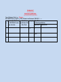
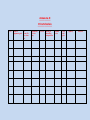
Central Purchase unit National Institute of Technology Srinagar-190006 Tel:- 0194-2424792/2429423/2424809/2424797 Fax:- 0194-2420475 *************************************************************** No. NITS/CPU/ /2015/Mech./1729-35 Dated.:- 12.11.2015 M/S………………………………….. ………………………………………. Sub: Invitation of Bids for the supply of Lab equipment for Material Laboratory of Mechanical Engg.Deptt Dear sir, 1…You are here by invited to submit your most competitive Bid for the lab equipment with detailed Specification of these goods as give in Annexure-A. The offer to be submitted in two bid System. 2. (Envelope- A (Technical Bid) It should contain the following; (As per tender opening format) (a) Authorization /dealership/manufacturer certificate. (b) Valid tax clearance certificate for bidders from J&K State. (c) Technical specification/ literature for the goods/equipment (d) Bid security @ 3% in the form of CDR in favour of Chairman, Central Purchase Unit NIT Sgr. and tender document fee Rs. 300/- in the form of DD, in favour of Director, NIT Srinagar. (e) Certificate of sale after sale service support wherever necessary. (f) Proof of legal status. 3. (Envelope-B (Price Bid) It should contain the following (a) Bid prices ( Preferably in Indian Rupees) (b) Bid price should be firm for the bid validity period. © All duties, taxes and levies (CST/GST/VAT or other taxes) payable, must be quoted separately. (d) As per SRO 129 of Government of Jammu & Kashmir, the institute is Exempted for state entry tax. The Institute will provide Entry tax exemption certificate to successful bidder with supply order. The Institute is also exempted for Custom/Excise duty. (e) The rate quoted should be FOR NIT Srinagar. (f) Bid price should be without over writing, however minor over writing should be clearly signed by the bidder. In case of any discrepancy between price quoted in figures and words, the price quoted in words shall be accepted. (g) The rates should be covered with transparent tape. (h) Bid form in the format given in Annexure-B (i) Technical specification Schedule as per Annexure-C (j) Price bid schedule in the format enclosed in Annexure-D 4. Validity of Bids Bids shall remain valid at least for 120 days from the date of opening. 5. Evaluation of Bids. (a) The purchaser shall evaluate and compare the bids which are found substantially Responsive. i.e which are (i) Properly signed (ii) Conform to terms and conditions and technical specifications. (iii) Accompanied with Bid security and all other documents. (b) Bids shall be evaluated separately for each item. 6. Award of contract (a Contract shall be awarded to the bidder whose bid is commercially, technically responsive and offered at lowest evaluated price. (b) Successful bidder shall be notified about the award of the contract where in terms and conditions of supply shall be incorporated. 7. 8. (a) 9. (a) (b) 10. 11. 12. 13. (a) (b) (c) Payment. 100% payment shall be made against delivery of goods at NIT Srinagar Campus in good condition, as per specifications and successful installation/commission. Warranty: All items shall carry comprehensive standard warranty of two years. Performance security. Successful Bidders shall submit performance security promptly after award of contract. Performance security shall be in the form of Bank Guarantee for the amount as mentioned in the award of contract letter/supply order. However it shall not exceed 10% of the contract value. Penalty for delay. A penalty of 0.15% (fifteen paisa per hundred ) per day shall be imposed if the supply is made beyond the prescribed period mentioned in supply order. Settlement of disputes. Settlement of any dispute will be made under the jurisdiction of Srinagar court. Liquidated Damages. If the bidder after accepting the purchase order of goods/equipments or services, fails to deliver any or all of the goods/equipments or to perform the services with in the specified period, a penalty of 15 paisa per hundred per day shall be charged. The maximum penalty can be limited to 10% of the cost. Once maximum is reached NIT Srinagar may proceed on its own to consider the termination of the supply order. Submission of Bids. The last date for submission of bids is 21.12 .2015 upto 2.30 P.M. Bids should be properly sealed. The two envelopes A & B should be kept in separate one envelope. Enquiry No., due date of opening and Quotation for supply of equipment for Mechanical Engg.Deptt. must be mentioned on this envelope. (d) Bids should be addressed to Chairman Central Purchase unit NIT Srinagar. (e) Bids shall be accepted up to one hour before opening. (f) Bidders not from Srinagar shall dispatch bids sufficiently well in advance s as to reach the destination one day prior to bid opening. 14. Bid opening (a) The Technical Bid (Envelope- A) will be opened first and price Bid (Envelope-B) of the bidder will be opened after qualifying the Technical Bid (Envelope-A). (b) Interested bidders can attend the bid opening. 15. Not withstanding above the purchaser reserves the right to reject any or all the bids. 16. We look forward for your quotation. Thanking you, Chairman Central Purchase unit, NIT Srinagar Note: 1. Before preparing your valuable bid kindly go through the document fully and take care of all the requirements. 2. Bidders from outside Srinagar may please send their Bids much in advance so that they are received in time. Annexure-A Schedule of Requirements. Details of Equipment:- Item specifications S.No 1 Qty Deliver y Period Load Frame Universal Testing Manual crosshead – up, down stop and jog control. Machine Cross head drive system shall be by AC Servo motor with high with precision low backlash Ball screw type. maximum Force accuracy of ±0.1% of applied load across the load cell display range or better. capacity of Displacement resolution of 0.0001 mm or better. 100kN for Speed resolution of 0.001 mm/min or better. conducting Built-in intelligent active force and displacement alarm system tensile, 32 bit precision motor controller flexural and 150% mechanical overload capacity or better. 20% digital load tare while maintaining full load cell capacity or other tests better. Automatic motor drive alarms that monitor over/ under voltage, current and temperature Position measurement accuracy: +/- 0.01% of reading or 0.001 mm, whichever is greater Speed accuracy: +/- 0.005% of set speed or better. Test speed range shall be 0.001 to 500 mm/min or better. Return Test speed shall be 700mm/min or better. Clearance between columns shall be 650mm or better. Load weighing system meets or exceeds the requirements of the following standards: ASTM E4, ISO 7500-1, and EN 10002-2. Load measurement system Load measurement accuracy: 0.2% to 100% of capacity of Load cell or better. Through the load cell confirming to EN10002-2, ASTM E4, and DIN51221. Grips Self-Tightening Wedge Grips shall have gripping length of 75mm/3 in. Temperature limits of -150 to 1200°C Tensile Testing Machine with software with facility to conduct and execute test Software To also be able to conduct a post test analysis. To be able to review test results at a later date. To include test generator (to be able to generate own test routines & test database (should include test software routines) as per international & Industrial standards 45 days ( ASTM/BIS/DIN etc.) Real time auto-ranging graphic display. Max. Data Processing Rate shall be 165MHz or better. Storage and retrieval of test parameters. Dedicated function keys for fast access. Input of test data and formatting of test report. Cyclic control between zero existing and a selected value of extension, force or strain. Stress calculations based on width and thickness or on width entries. Shall be Bluetooth enabled with v4.0with A2DP,LE,EDR. Electrical connection – 220 V/1 phase/50Hz Humidity range: 10% to 90% non-condensing, wet bulb method Weight of the machine shall be 800kg or less. Shall supply Computer with 4GB RAM, 2 GH z Pentium Dual Core or better, 40 GB of available hard disk space (minimum). Machine communication through RS 232 or USB and one additional USB port for software. DVD-ROM Drive (to run installation DVD), Mouse or pointing device and keyboard supported by Windows , Monitor - 32-bit color, 1600 x 900 (Widescreen) or higher, Windows compatible printer, Windows compatible sound card and speakers. 2 Specifications of the Impact testerPendulum Basic Pendulum Capacity: 400 J or higher Impact Drop Height: 1.52 m Tester for Impact Velocity: 5.3 – 5.47m/s Digital Display facility should be available Metals with Electronic Brake facility should be available Digital Charpy Set-up including Striker, centering tongs and anvils as Display per (ASTM E 23) should be provided Izod set-up including striker, height setting gage and anvil should be provided Notch cutting blade should be supplied along with the Impact tester Electric Supply: 220-240V, 50-60Hz AC Pendulum Impact Tester for metals should comply with the latest requirements of ASTM E 23 and ISO 148. The microprocessor impact Display, should be provided with a backlit LCD display and key pad membrane for conducting the test, obtaining test results, calibrating and configuring the system. Other features should include: Port for output of test data to a serial printer or to a computer Automatic windage and friction correction Windage and friction loss should be displayed and it should not exceed 0.5% Automatic or manual update of specimen number Operator selectable energy units of in.- lbf, ft-lbf, Joules, kg-m, kg-cm Units of ft-lbf/in., J/m, in.-lbf/in., kg-m/m, ft-lbf/in², kJ/m², in.lbf/in², kg-m/m² should be selectable. Charpy setup Carbide Striker (ASTM E 23) : Charpy Striking Tup for testing in accordance with ASTM E 23 Charpy Centering Tongs: Self-Centering Tongs for properly setting Charpy specimens in the machine, especially those which have been subjected to either heat or cold. Charpy Anvils Izod Setup Izod Striker: Izod Striking Tup. Metal Impact Izod Height Setting Gage: A Notched Izod Height Setting Gage is required to clamp the 10mm square izod specimen firmly in the support vice so that the centerline of the notch is in the plane of the top of the vise within 0.125mm (0.005in.). Izod Anvils. Acceptance criterion Vendor to calibrate applied system as per ASTM E23 at purchaser’s site as the part of installation. Machine should confirm to the CE directives 3 Rockwell and Brinell hardness tester Basic Unit: Basic unit with accessories shall perform tests in accordance with ISO 6508, ASTM E18 and other relevant international standards. Scales: Rockwell: All scales Superficial Rockwell: All scales Brinell : All Scales Load application & measurement: Fully automatic, load cell based, closed loop system Pre-load 3kgf & 10kgf Main load Up to 150kgf Dwell time: 1-99s or better Test cycle: Motorized, Fully automatic, Load,Dwell, Unload Process. Specimen: Height: 250mm or higher Width : 175mm(from center)or higher Display: 6.5” or higher color touch screen for control settings, results, statistics, conversion values, shape correction etc. Hardness conversion: Vickers, Leeb, tensile etc. Power: 240V, 50Hz, single phase Connectivity : USB, RS232, LAN Weight: shall be 120kg or less Standard supply: Basic unit shall consist of: Brinell Microscope 6.5” touch screen V anvil Flat anvil 60mm Precision spindle Installation & user manual Certified Rockwell diamond indenter – 2no. Certified 1/16” carbide ball indenter – 2no. NVLAP or UKAS certified Rockwell C block - 2no. NVLAP or UKAS certified Rockwell B block - 2no. 01 No 4 MicroVickers Hardness tester NVLAP certified Brinell Ball indenter 2.5 mm -2 no. NVLAP certified Brinell hardness standardized test block – 02no. Frame Basic unit with accessories shall perform tests in accordance with ISO, ASTM, JIS & other international standards. Scales: Micro-Vickers Test selection procedure: Manual Test Procedure: Automatic, loading/dwelling/unloading Turret: 4 positions over 360°, automatic, memorized start position, 1 indenter and 3 objectives Dwell Time: User defined, 1 to 60s , Shall have built-in high speed thermal printer. Specimen: Vertical Capacity: 90mm or better Horizontal Capacity: 120mm or better User Display: Length of diagonals, hardness value, converted value, test force, online statistics Rockwell, Rockwell Superficial, Brinell, Leeb & Tensile Resolution 0.1HV, HK Digital Microscope: Eyepiece shall be bright dual line filar eyepiece with 15x magnification with a resolution of 0.1µm or better reading. Objectives supplied shall be of 10x , 20x, 40x. Power: 100V AC to 240V AC, 50Hz, single phase Connectivity: USB or RS232 Weight: shall be 40kg or less. Operating Temperature Range: 5° to 40°C (41° to 104°F). Operating Humidity Range: 10% to 90% non-condensing. Stage Dimensions 100 mm x 100 mm (3.93" x 3.93") or better Travel 25 mm x 25 mm (.98" x .98") or better Reading 0.01 mm (.00039") or better Standard supply: Basic unit shall consist of: Manual X-Y stage Objectives (10x, 20x and 40x) Electronic microscope 15x Certified Vickers indenter – 1no. Certified test block – 2no. Built-in silent thermal printer Set of work- piece fixtures, vice, chuck, clamp, adjustable feet Spare halogen lamp Installation and user manual. Optional Vendor to quote for 2MP or higher camera, PC, software for onscreen hardness measurement, brightness/contrast adjustment, pass/fail limit setup, program & data storage, report generation, Shall supply Vibration free Study table 5 Video Gauge System For Material Testing Applications Torsion 6 Testing Machine A non-contact single camera system shall work on pattern recognition technology which tracks point to point movement on the specimen in real time. It shall work as a standalone system or with computerized UTMs to perform measurements like axial & transverse strain, shear strain, Poisson’s ratio, distance, rotation & displacement in tensile, compression, 3 point & 4 point bend modes. This system shall have following features: Non-contact continuous measurement through sample break Multiple measurements between 200 or more points in given field of view (FOV) Time stamped measurement High strain measurement upto 1000% Temperature testing in the range of -190 0C to + 1200 0C Harsh environments compatibility (chemical/radioactive) Cool low energy lighting to avoid specimen heating Video record or discard facility Multiple measurements facility from recorded video Raw data availability to use with programs like MS Excel, Ansys, Matlab etc. UKAS accreditation Technical details Real time strain measurement in both longitudinal and transverse direction Range: 0.1 - 1000% or higher Accuracy: ISO 9513 Class 0.5, ASTM E83 Class B1 or better Resolution: 1/100000 of lens FOV or better Results: %strain, elongation in mm or %, displacement in mm, Poisson’s ratio, modulus, rotation in degrees Vendor shall supply all necessary accessories like GigE PoE camera, 1MP or higher Variable lenses with 8mm, 25mm & 50mm focal length, 2μm or better resolution Material test lens with FOV of 32 x 24mm, resolution 0.15μm or better resolution Cool LED light panel for illumination Sturdy, multi-adjustment tripod I/O module with 8AI, 2AO Complete software for video recording & post processing functionality, multiple target fixing, axial strain & transverse strain, shear strain, displacement, distance, rotation & Poisson’s ratio measurement, I/O signal calibration facility High end dedicated controller to take upto 4 cameras Max. Torque Capacity 1000 Nm Vendor to offer compact, bench mounted torsion tester with digital control Loading system shall be Through electromechanical system with variable speed drive, Bi-directional Application: To provide a machine to measure angle of twist, torque machine should be capable of measuring the turning angle upto 360 degree and above and should determine the specimen behavior under continuous or intermittent torque loading in both directions. Machine should be capable of conducting torsion test on both metallic and non-metallic materials Torque measurement: Accuracy of +/- 0.5% of indicated torque over the range of 0.2 to 100% capacity. Torque range should be adjusted by auto torque or torque can be applied to specimen by geared motor through gear box. Specifications: Specimen diameter- 35mm or higher, Specimen length- 450 mm or higher,Test speed range- 0.5 to 360 deg/min or better Speed accuracy : ± 0.1% of set speed or better Position accuracy- 0.050 deg or better Output- High speed RS232 or USB Power supply- Standard 220/240 VAC, 50Hz, Weight- 500 Kg or less. Handheld controller: Hand held controller with LCD display. It shall allow to setup machine, control & display results like force, displacement etc. Gripping system: Bi-directional grips to ensure slip-free clamping regardless of the twist direction Software platform: Tabbed navigation for easy user interface Fully customizable report format Fully customizable screen layout Multiple graphs on same screen & report to observe multiple events at the same time Curve regenerations, post data analysis Pass/fail limits Advanced windows style password security to manage & secure data Online support for test methods, reports should be available from the helpdesk Graph of tests should be available Auto graphic recorder that gives relation between torque and angle of twist. Service & local support: Shall provide service support for supplied instrument through factory trained personnel. Shall be able to take AMC including calibration of system. Supplier should also provide necessary manuals and experimental manuals to be performed on equipments. 7 Fatigue Testing Machine: One set of Digitally controlled, closed loop, Servo-hydraulic Fatigue Testing Machine of 100KN Capacity with the following basic Features: Load Frame Capacity: +/- 100 KN static and dynamic loading. Construction: Free-standing, Rigid, Heavy-duty precision aligned high stiffness two column intelligent loading frame with fixed lower platen and adjustable upper cross-head, ensuring all operations at ergonomically convenient height for efficient operation. Height: Vertical (Cross head to base platen) : >1400mm. Horizontal (Width between two columns) : >600mm. Upper Cross Head: Hydraulically operated, fitted with hydraulic lifts for adjustment of upper cross head at variable heights and hydraulic clamps for position-locking of the crosshead with all the operations linked/integrated with electronic controls. Lower Platen: Integral, Actuator mounted and with all other controls. Actuator: Capacity: +/-100 KN; Total stroke: 150mm (+/75mm) the servo-hydraulic actuator shall be fitted complete with stroke transducer, servo-valve, filter, accumulator and actuator electronic system for signal conditioning and control. Signal conditioning units to be of integrated modular type. The actuator provide with labyrinth bearing should be coupled with internally mounted LVDT for precise measurement of actuator displacements. Provision shall also be made for a hand-held control mechanism with operational facilities for Actuator positioning, grip control etc. Manifold/Servo Valves Hoses: Hydraulic service manifold mounted directly to actuator system with servo-valves of suitable capacity and hoses of rated capacity compatible with the hydraulic power package offered. Hydraulic Power Pack: Water cooled power pack of sufficiently rated capacity of above 60 L/min nominal flow at 280 Bar on 60Hz. 280 bar maximum output pressure with guaranteed high service life shall include matching Pump, highly efficient cooler (water) for maintaining oil temperature, protection devices for oil conditions viz. Oil level, temperature, filter and pressure, power level, over-load, filter blockage warming besides facility for emergency stop for pump. Offer shall also include specifications for quality and quantity of oil required and complete fill of oil at the time of supply. 3micron pressure and return line filtration. Local or remote start/stop functionality. Star-Delta starting shall allow hydraulic power supply to be started and stopped from control panel. Pump should be outside the power pack. Operational Voltage: 415 (+/-10%) V, 3Ph., 50Hz power supply. Preventive Devices & Controls: Anti-Vibration Mount: Provision shall be provided to prevent vibration transmission to the Laboratory floor. Anti-Rotation Device: Provision to suit the purpose to prevent rotation of the holder with the specimen from the axis for effective functioning of the testing machine. Grip Control: Effective interlocking of the grips with the controls so the user cannot open grips while running a test. Noise & Filter: Within satisfactory operational limits. Amplitude Control: Provision for full amplitude and mean level control shall be available. Adaptive Control : 6 term control for PID, Lag, Feed-forwarded & notch system shall be provided. Shall allow continuous update of PID terms at 1KHz, eliminating the need for operator set-up and automatically compensating for specimens stiffness. Resolution: System resolution should be 19 bit across the complete span of the sensor. Transducer Filtration: Filtration range is preferred from 0.001Hz to 1 KHz in increments of 0.001Hz which is necessary for LCF Test. Load Cells: Capacity: +/- 100 KN, Dynamic Inertia Compensating type with an over-load capability of over 150% capacity without mechanical failure. Accuracy: +/-0.25% of load reading from full capacity down to 1/100 of range. Basic Characteristics : Auto-transducer recognition ; Signal conditioning of transducers to offer greater stability and low noise levels with transducer filtration system facilitating infinite adjustment in the range of 0 to 1 KHz (0.001 Hz steps). Frequency: 0.01 Hz to 100 Hz. Calibration Validity: The interval of calibration of the testing machine should be quoted to ensure the period of validity of test results. Extensometer: Dynamic extensometer for direct strain measurement & close-loop strain control suitable for tensile & fatigue testing with varying gauge length of 12.5/25/50mm and travel +/-5mm. Operator’s Franchise: The testing should offer dual mode control viz. manual control & computerized automatic control. There shall be provision for the operator to opt for either or both the control modes and ensure a virtual standby in case the computer does not work. Control System Control Panel: The system should be provided with state-ofthe-art Digital Controller with high resolution and different functional modules placed in server type cabinet with facilities of digital linearization, adaptive control, low noise of 2 - 3mV & manual control panel with intuitive user interface. Filtration system variable between 0 to 1KHz data acquisition rate should be about 5KHz continuous & synchronous in all channels. PC interface to machine should be faster data transfer rate (7MB/sec) through GPIB interface. Specimen protection facility should be provided for complete safety for the specimen installation. It should allow at least 4 control modes & high precision control loop updating the system to the desired level, when necessary. It should have facilities to run either or both the frames at any time, as necessary. It should be provided with adequate protection device, applicable for a modern sophisticated testing machine. 8 digital I/O and 4 analogue outputs per controller. Multi-function Microprocessor System: The P.C.B. of digital control electronic system & also advanced console with suitable software should be designed to offer the following functions for efficient & foolproof operation of the testing machine. Operator Panel: 32 Bit up to 1KHz waveform generation; Transducer recognition & calibration, Mode changing, Limit setting, Digital displays, Continuous synchronous data acquisition on all channels, Service data play-back digital display, Overload protection etc. as feasible by present day advanced electronic control system & advanced sensor technology in the field. The electronic system shall have additional provision for modification/updating the system in the long run. The controller should be provided for an adequate number (slots up to four) of conditioning modules and automated dynamic control mode switching between the connected transducer in a bump less manner. Computer System Computer : Minimum Specification that will be supplied as follows: - Intel Core 2 Duo Processor E6750 (2.66 GHz, 4 MB,1333 MHz) - Vertical Chassis Orientation (Minitower, W: 170,2 x H: 447.3 x D: 468.4 mm) - 2GB DDR2 667 ECC Dual Channel Memory (2x1GB) - 160GB (7,200rpm) SATA2 Hard Drive - 16X DVD+/-RW - 256MB PCIe x16 nVidia Quadro NVS 290 (ULGA8), Dual Monitor DVI or VGA Graphics Card - Internal Speaker - 1 x Integrated Ethernet Port and 1 x Ethernet PCI-E Network Card (for use with Ethernet Frame Interface) - 3 PCI Slots (2 full length, 1 short length) - 1 free PCI Express Slots - Dell Black 2 Button USB Scroll Optical Mouse Software: The interface & software should be compatible PC based. Detailed specifications of the computer required for running various software packages should be listed and the computer system to be quoted separately. Comprehensive, Operating system: Win XP Professional, Professional or NT based, soft- ware packages to conduct tension, compression, bend, fatigue (fatigue crack growth and adequate provision for future up gradation for low cycle fatigue) and fracture toughness (both K1C and J1C) properties as per appropriate standards, should be included. Each software should be quoted separately. Program: All software must be 32 bit running in Windows XP Professional or Windows7. Program for Tensile Test : Program for conducting tensile test to latest issues of specifications : BIS,BS 18, ISO 6892, EN 10002, ASTM E-8M, DIN50-145 & GOST 1497 for determination/direct reading of the following characteristics : Upper yield stress & lower yield stress. 0.2% proof stress (off set). Ultimate tensile strength. % elongation. Graphical representation of stress Vs strain curve on screen in real time and provision for copying the graphical presentation per graphic printer. Program for Fracture Toughness (Pre-crack) : Programmed for growing a fatigue crack at a controlled and specified stress intensity at the crack tip as per ASTM E-647. The test shall be automatically stopped at the pre-specified crack length. The crack length cycle count shall be stored and printed at regular intervals during the test. Program for Fracture Toughness (Fracture) : Program for fracture of the pre-cracked specimen at a programmed rate at a selected control mode as per ASTM E-399. The crack opening displacement should be measured with a clip gauge. The signal and the load should be stored during the test. This program should use the data file from pre-crack for the pre-test information. The equipment shall also include provision for low cycle fatigue test facility. Other Fracture Mechanics Software: CTOD tests according to ASTM E 1290-08e1. Shall have unloading compliance software to perform JIC tests as per ASTM E 813-89. Shall have software package to perform tests according to ASTM E 1820-09e1 enabling determination of fracture toughness of metallic materials using K, J & CTOD. Program for LCF Test: Program for LCF test with real- time graphs, calculation of results, storage of data to disk and post test graphs and reports in accordance with ASTM E-606. For determining LCF test Automatic PID controller ie, Adaptive control is must for automatic changing the PID Control 1000 times per second. Program for Single Axis Fatigue test: Single Axis Fatigue Package – Operating System: Win XP Professional, 95, 98, 200 Professional or NT. Standard and user- defined (ASCII input) waveforms. Waveform Preview window: graphically displaying how the test will run. Data acquisition from up to four transducers and up to 16 high – level signals. Capabilities for tension, compression, flex, and fatigue tests with data storage to disk. Shall allow Ramp, hold, sine, triangle, square, and trapezoidal waveforms for control in a series of test blocks. Shall support block to block event triggers. Shall display up to five user defined real-time graphs. Waveform preview window shall graphically display how the test will run. Data storage to computer disk in ASCII format at rates up to 5kHz continuous. Continuous, periodic, or logarithmically decreasing data storage. Up to four independent, simultaneous real time graphs. User input for on-the-fly changes to test waveform mean level and amplitude. Save / recall test setups from computer disk On-line help system. Status and Display software, which shall appear at the top of the PC screen while using the other software. Status and Display shall provide digital displays of transducer values, cycle counts, and elapsed test time, as well as system status information such as test system control mode and limits. Grips and Fixture Hydraulic Grips and Manifolds: Hydraulic grips of capacity: 100 KN static and dynamic loading with suitable grip control manifolds quality: one pair. Control of the grips shall be via a frame mounted handset and the grips shall be interlocked to prevent opening when the system is in load or strain control for safety reasons Jaw Faces: For holding flat specimens of width: 50mm & thickness ranges up to 15mm. Vee Jaw Faces: For holding round specimens of diameter ranges 6mm to 16mm. Bend Fixture: Three points bend fixtures suitable for bend testing of test specimens within the rated capacity of the machine: one set. Clevis Grips: For holding 6.5mm,13mm and 25mm thickness CT specimens. COD Gauge: One (10mm GL), 4mm Travel + -20 to +60 deg C. Environmental Chamber: (-150°C to 1000°C). 3-zone split furnace for testing up to 1000°C on the test specimen. Set of 4 Type N thermocouples, 3 for control, 1 for alarm. Excludes specimen monitoring thermocouple. Temperature control system featuring 3x Independent Eurotherm 3216 controllers capable of following a single ramp to set-point. and 3448 ESeries self-supporting extensometers (up to 50mm GL, +50% Travel). 220-230 volts 50/60Hz single phase operation. Set of Furnace Support Bracketry to suit 8862 machine option Set of 2 insulating refractory top/bottom insulating port plugs to suit pull rods, 64mm bore. Extensometer: Low temperature and High temperature strain gauge extensometer suitable for use up to 1000 °C in resistance furnace. 12.5mm gauge length +20% -10%. Specimen strain is transmitted by means of quartz chisel end rods through an aperture in the furnace wall. Attaches to specimen using ceramic wrap around cord or using spring attachment. Outside the furnace the rods secure to the extensometer body. Strain gauges arranged in a fully active Wheatstone Bridge are bonded to a flexural element within the extensometer body. Manufacturer has to provide ISO-9000 or equivalent international certificate. All the necessary items are to be mentioned for commissioning this equipment. Details of the service personnel are to be mentioned. Calibration facility should be mentioned in detail. References of this offered Model are to be mentioned. Dynamic Performance curve to be submitted in the Offer. All the necessary details are to be mentioned in offer eg; Chilling water, motor, UPS, Etc. from Indian Sources. (Tender opening format) Name of the firm:-_____________________________________________ Tender for supply of ___________________________________________ NIT No. & Date:- ___________________________________________ Technical specification/ literature attached:- Yes/No Valid tax clearance certificate attached:- Yes/ No Registration/ Authorization Dealership/ manufacturer certificate attached:- Yes/ No Revenue stamp affixed. Yes/ No Rates covered with transparent tape:- Yes/ No Bid document fee deposited:- Yes/ No Call Deposit Receipt enclosed:- Yes/ No. Bid price in Indian Rupees:- Yes/ No FOR Srinagar:- Yes/ Bid without correction/overwriting:- Yes/ No No Seal & Signature of the Supplier. Annexure-B BID FORM **************** From M/S……………………………… ……………………………………….. To, Chairman, Central Purchase unit, NIT Srinagar. Ref: NIT No.: NITS/CPU/ /2015-16 Dated:.....................................goods/Equipment for ………………………………Department Sir, With reference to above invitation for bids we would like to say that we have gone through your bid document thoroughly and hence offer our competitive Technical/Price Bid in sealed envelope for the supply of various goods/equipment listed in your document. The following documents constitute our Bid. (a) (b) (c) (d) (e) (f) (g) (h) Bid form Price Bid schedule in the requisite format Authorization dealer ship certificate from the manufacturer Valid sales tax certificate Technical literature for the goods/equipment Names of organization where this equipment has been supplied. (Applicable for equipment whose unit price exceeds Rs.2.00 lacks Bid security as mentioned in the schedule of requirements in the form of CDR drawn in favour of the Chairman Central Purchase Unit NIT Srinagar. Telephone No………………………………………………. Kindly feel free for any enquiries and clarifications. Yours Sincerely (……………..) From M/S……………….. Place…………………. ………………………….. Date…………………… Annexure-C ************** Technical specification. *************************** Name of Equipment /Goods : e.g., Tribometer Make /Model/ Country of origin: e.g., Marus Tribometers and Instruments/ TR20-2013/ ……... S. Technical Specifications (as Technical Complies Higher/Better No. per. NIT/CPU/13/ aaaaSpecifications of the (with detail quantification) aaaa Advertised) Make /Model Higher/Better Quantification 1 2 3 Yes ---- Higher Annexure-D ********************** Price Schedule **************************** S. No Name of equipment/goods Ex Factory/Ex show room cost Custom Duty & Excise Duty CST/VAT Packing & forwarding transportation Incidental services Total unit price Quantity Total Price