1
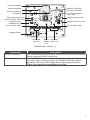
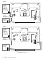
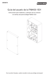
Internal Antenna
Receive LED (D4)
Transmit LED (D5)
2 | 4 Wire Jumpers
(J19, J20)
Antenna Module
External Antenna
Connector
Power Connector (J2)
Power/Tamper LED (D3)
Tamper Switch
Connector (J1)
Link 1 Button (S2)
Link 1
LED
USB Connector (J9)
Link 2 LED
RS485 Connector (J5)
Link 2 Button (S3)
Tamper Switch
Not used
(J8, J7)
Reset Not used
Button (J10, J11)
(S1)
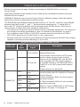
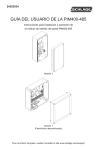
PIM400-485 (Version 1)
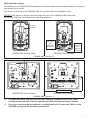
Component
RS485 connector
Power connector
Description
The PIM400-485 connects up to 16 WAPMs to an Access Control
Panel using the RS485 connection.
The PIM400-485 power input is non-polarized. If power is lost
or cycled, upon restoring power, the PIM400-485 will continue
operation with the same configuration and linking information.
There is no need to re-configure or re-link.
5