1
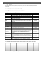
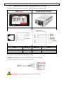
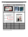
IMPORTANT
The controller delivered with this manual may be modified for specific needs.
In this case, please give us the controller serial number written on our shipping note or the
approximate controller delivery date when you will place an order for a new similar controller or for
spare parts.
In this way, you will be sure to get the required controller and/or spare parts.
WARNING
This information has to be kept in a location known to all users.
Each operator has to read carefully this instructions manual before installing,
using, and mending the product.
Be sure that the operator has understood usage recommendations and the meaning of signs put on
the product.
Most accidents could be avoided respecting this Instructions Manual. As a matter of fact, they were
created according to European laws and norms applied to the product.
In each case, please respect and follow national safety norms. Do not take off nor damage the
stickers or notifications put on the product and above all the details imposed by the law.
SUMMARY
1.
2.
SPECIFICATIONS .................................................................................................................... 3
HARDWARE .......................................................................................................................... 4
2.1
Dimensions and mounting interface ....................................................................................... 4
2.2
3.
4.
5.
6.
Interface ports ......................................................................................................................... 5
GETTING STARTED................................................................................................................. 6
MAIN MENU ......................................................................................................................... 6
JOB MANAGER ...................................................................................................................... 7
NEW JOB CREATION .............................................................................................................. 8
6.1
Fastening step creation ........................................................................................................... 9
6.1.1 Manual programming of fastening step:.............................................................................. 10
6.1.2 Automatic programming of fastening step: ......................................................................... 11
6.1.3 Smart tolerance detection feature: ...................................................................................... 11
7.
8.
9.
6.2
Logical Input step creation .................................................................................................... 12
6.3
Logical Output step creation ................................................................................................. 12
6.4
Delay step creation................................................................................................................ 12
6.5
Message step creation .......................................................................................................... 13
6.6
Job example ........................................................................................................................... 14
SETTINGS ............................................................................................................................ 15
7.1
Operating............................................................................................................................... 15
7.2
Encoders ................................................................................................................................ 17
7.3
Inputs ..................................................................................................................................... 18
7.4
Outputs .................................................................................................................................. 19
7.5
Network ................................................................................................................................. 20
7.6
Other ..................................................................................................................................... 20
OPERATING MODE .............................................................................................................. 21
ELECTRICAL WIRING ............................................................................................................ 22
9.1
Encoder’s port wiring scheme ............................................................................................... 22
9.2
RS232 port wiring scheme ..................................................................................................... 22
9.3
Inputs wiring scheme ............................................................................................................ 23
9.4
Outputs wiring scheme ......................................................................................................... 24
9.5
Connection of DOGA low voltage tools GX/GY/DO/GA ........................................................ 25
9.6
Connection of DOGA Hybrid HDC and Current control SDC tools ......................................... 26
9.7
Connection of Stanley Alpha and Kappa tools ...................................................................... 28
9.8
Connection of Kolver EDU Series tools .................................................................................. 29
9.9
Two tools wiring example ..................................................................................................... 30
9.10
Automation equipment wiring example ............................................................................... 31
9.11
I/O port adaptor (DB44
DB25 + DB9) wiring scheme ....................................................... 32
10. Troubleshooting.................................................................................................................. 33
DPC Touch User Manual
1. SPECIFICATIONS
No
Specification
1. Input power
DC24V, 1A
AC 100-240V / DC 24V adaptor is provided
2. Dimensions
202(W) x 128(H) x 38(D) mm
3. Weight
0.55 kg
4. Screen
7” LCD Touch screen, 800 x 480 px
5. Graphical interface
Visualization of assembly process with graphical instructions
6. Inputs and Outputs 24V
12 inputs and 12 outputs with assignable functions
Logical I/O’s for workstation automation
7. Analog encoders
4 channels, 0...5V
8. Memory card
Removable SD card, 8Gb
9. Total jobs memory
999 jobs with open structure
10. Total positions memory
999 jobs x 255 steps x 99 positions per fastening step
max 999 positions in one job (counter limit)
11. Programming
Automatic and manual programming of a Fastening step
12. Positioning accuracy
0.09° for angular encoders
<0.5 mm for linear encoders
13. Positioning tolerance
Adjustable for each position and for each axis.
Smart tolerance detection feature.
14. Compatible tools
All tool with signals – electric or pneumatic.
Min required signals: «Fastening OK», «Tool Lock»
15. Communication
RS232 for bar code scanner and firmware upgrade
Ethernet (not enabled in firmware v.0.2.8)
3
DPC Touch User Manual
2. HARDWARE
2.1
Dimensions and mounting interface
Mounting plate with 4 x M3 screws is delivered with the controller as a standard accessory.
Weight of the controller: 0.55 kg
4
DPC Touch User Manual
2.2
5
Interface ports
Power supply
SD card
Ethernet port
USB mini-B port
1:GX,GY,DO,GA
USB-B port
2:GX,GY,DO,GA
I/O port DB44
Encoders
RS232
NOTE: ports shown in grey are not used in firmware v.0.2.8
I/O port adaptor
This adaptor is used to split I/O signals for
tool interface and other automation
equipment (see Electric wiring chapter for
the wiring scheme).
Encoders port adaptor
(supplied only for controllers with serial numbers
starting with SC******)
Encoders port adaptor is used to connect standard
DOGA positioning arms to DPC Touch.
ATTENTION: Do not connect positioning arm directly to
DPC Touch (serial numbers starting with SC*******)!
This may damage encoders!
DPC Touch User Manual
6
3. GETTING STARTED
1. Connect power supply to the controller to turn it on. Normal booting time is about 2 sec. If
controller is not booted, the last booting step indicates the problem (e.g. Init SD Card… missing or damaged SD card).
2. After first booting, calibration screen may appear. Follow instructions on the screen -press
and hold the center of the cross for 1 sec for each position of the cross.
ATTENTION: if calibration is not correctly performed, the touch screen may become
unresponsive. In this case turn off the controller, take out the SD card, access the SD card
from your computer and delete the following file: SD:\system\setting\Setting_posi.dat
3. Controller is started automatically in operating mode. If default job is selected it will start
automatically.
4. Tap on the HOME button in order to access to the main menu screen. While not logged in,
JOB MANAGER and SETTINGS are not accessible.
5. To log into the system tap on the LOGIN button. Default factory password is “0”.
4. MAIN MENU
The main screen provides access to the main menu with four buttons:
-
-
Job manager
Provides access to the list of saved jobs and allows creation/modification jobs. This button is
locked while user is logged out.
Operation mode
Provides access to the operating screen.
Settings
Provides access to the controller settings. This button is locked while the user is logged out.
Login/Logout
Allows logging into the system by entering the password to access Job manager and Settings.
NOTE: default factory password is “0”. If the password is lost, turn off the controller, take out the SD
card, access the SD card from PC and delete the following file: SD:\system\setting\Setting_posi.dat
After rebooting, the controller will be reset to default factory settings.
DPC Touch User Manual
5. JOB MANAGER
Job manager interface provides access to the list of saved jobs. It also allows to Edit or to Delete
saved jobs as well as to create new ones by pressing New button or by Copying an existing job.
Load button is used to load selected job into operating mode.
NOTE: a job can’t be loaded if it doesn’t contain any steps.
Each job has its sequential number (№). In order to change job number tap one more time on the
selected job and then change its position in the list by using Up and Down buttons.
For information purposes number of steps and screws in a job is displayed in corresponding line in
the list.
Home button provides access to the main menu screen.
Maximum number of jobs is 999.
NOTE: while not logged in, the only active buttons are Load and Home, other buttons are locked.
7
DPC Touch User Manual
8
6. NEW JOB CREATION
While in Job Manager screen, press NEW button. New job will be created and placed in the end of
the list. New job creation screen will be displayed automatically.
A job is represented by a sequence of steps. These steps can be organized in any order which
corresponds to the desired production sequence. There are 5 types of steps and each one of them
can be used multiple times if necessary.
-
Fastening: this step contains fastening positions including information associated with these
positions (positioning tolerance, tightening program, tightening time, etc.)
Logical In: this step is used to verify an input signal in order to pass to the next step (e.g.
signals from proximity sensors, buttons, etc.).
Logical Out: this step is used to send an output signal(s) to manage automation equipment
on work station (e.g. activation of pneumatic valves, lights, etc.).
Delay: this step allows to maintain the current state of I/O’s for specified time (e.g. a delay
required between receiving an input signal and sending an output signal).
Message: this step is used to display a graphical or text message on the operating screen
during working cycle.
A job may contain up to 255 steps. The maximum number of positions in a single fastening step is 99.
In order to change sequence of steps in a job, tap one more time on the selected step and then
change its position in the list by using Up and Down buttons.
Created steps can be modified by using EDIT button or deleted by using DELETE button. COPY button
creates a copy of the selected step and inserts it in the end of the list.
Press SAVE button to save the job or CANCEL button to quit programming without saving changes.
DPC Touch User Manual
6.1
9
Fastening step creation
NOTE: it is useful to define encoder’s reference point before creating a fastening step. See encoder’s
settings for more information.
While in Job creation screen, tap on FASTENING step button. The Fastening step creation screen will
appear.
Current field displays the number of position being programmed.
Saved field displays the total number of saved position in the fastening step being programmed.
Current channels fields display current values from analog encoders. Only active channels are shown.
Saved channels fields display saved values from analog encoders. Current values are saved when
Apply button is pressed or when Fastening OK signal is received.
Tolerance fields display tolerance values for analogue encoders to be applied for each encoder for
the current position. Tolerance values can be automatically detected by using Smart Tolerance
detection feature (please refer to corresponding chapter for more details).
Approaching area (orange):
Tool is disabled
Out of position area (red):
Tool is disabled
OK zone (green):
tool can be enabled
Screw
NOTE: real shapes of tolerance areas are not circular; they depend on the geometry of the
positioning arm being used. To avoid overlapping of tolerance areas of different screws, keep
tolerance values as low as possible.
DPC Touch User Manual
10
Time control fields display measured Tightening time and calculated Min and Max limits. Min and
Max values are calculated according to percentages defined in operating settings.
Tightening job is a preset number to be selected for the current tightening position via 24V outputs
(direct or binary logic) if supported by the tool.
Retightening job is similar to the Tightening job but it is used only for rework operation and it is
automatically selected after NG tightening (if retightening is enabled in operating settings).
Pick up positions 1 and 2 can be selected to allow to start the tool in a specific position or area
(outside position OK zone) in order to pick up a screw. Fastening OK signals and Motor run signals are
not effective on pick-up position.
Driver 1 and 2 selection is only applied to DOGA tools (GX, GY, DO, GA) connected through RJ45 port.
This selection allows enabling and disabling tools for each individual position.
Reset button is used to reset current position data to default values. To delete a position press Reset
button one more time after resetting the position data to defaults.
NOTE: there is no need to use APPLY button after modification of any of the above values. APPLY
button is only used to save current values from encoders for the current position.
A Fastening step can be programmed manually or automatically.
6.1.1 Manual programming of fastening step:
0. Optional: Use Smart tolerance detection feature (refer to Smart tolerance detection below)
1. Position the arm on the first screw.
Encoders monitoring fields are displaying the current position of the arm.
2. Press APPLY button to save current position of the arm. Saved values from encoders will be
displayed in corresponding fields. If not satisfied with the result press APPLY button again to
rewrite saved values from encoders.
3. Default tolerance values for the approaching Area and for the OK zone are applied. To
change default values refer to encoders’ settings. Tolerance values can be adjusted manually
for each individual position or by using Smart tolerance detection feature.
4. If necessary, define Tightening and Retightening programs to be used for the current
position, feeding point (see Pick Up positions in encoders’ settings) and the screwdriver to be
used for this tightening position (used only for DOGA GX/GY/DO/GA tools).
5. If necessary, enter Min and Max tightening time limits in corresponding fields. Tightening
time control is not used if limits are equal to 0.
6. Press NEXT button to pass to the next position.
7. Repeat 1-6 for each position.
8. Activate Non-sequential mode if there is no need to keep strict tightening sequence.
NOTE: in non-sequential mode, retightenings can’t be managed.
9. Press SAVE button to save the step or CANCEL button to quit programming without saving
changes.
DPC Touch User Manual
11
6.1.2 Automatic programming of fastening step:
For automatic programming, make sure that the tool is connected to the controller and signals are
correctly assigned. In order to register tightening time, Motor run and Fastening OK signals have to
be connected.
0. Optional: Use Smart tolerance detection feature (refer to Smart tolerance detection below)
1. Position the arm on the first screw.
Monitoring fields are displaying the current position of the arm.
2. Default tolerance values for the approaching Area and for the OK zone will be applied. To
change default values refer to encoders settings. Tolerance values can be adjusted manually
for each individual position or by using Smart tolerance detection feature.
3. If necessary, define Tightening and Retightening programs to be used for the current
position, feeding point (see Pick Up position in encoders’ settings) and the tool being used.
4. Perform a tightening operation as it has to be performed during production.
5. Tightening time will be registered automatically. Min and Max tightening time limits are
calculated automatically by using default values in operating settings. Tightening time control
is not used if limits are equal to 0.
6. Repeat 1-5 for each position.
7. Activate Non-sequential mode if there is no need to keep strict tightening sequence.
NOTE: in non-sequential mode, retightenings can’t be managed.
8. Press SAVE button to save the step or CANCEL button to quit programming without saving
changes.
6.1.3 Smart tolerance detection feature:
This feature allows automatic detection of OK zone tolerance for each position. Motor Run signal has
to be connected in order to use this feature.
1. Press START button to begin smart tolerance detection.
2. Start the tool and move it around the screw to define OK zone (the zone where operator is
allowed to run the tool).
3. Stop the tool and press STOP button on the screen.
Or perform a tightening operation as it has to be performed during production.
In this case tightening time will be saved automatically together with detected tolerance
values and current position coordinates. Next position teaching will start automatically.
4. Continue with Manual or Automatic programming.
DPC Touch User Manual
6.2
12
Logical Input step creation
While in Job modification screen, tap on LOGICAL IN button. The Logical In step creation screen will
appear.
Select an available input from the list of Inputs. If an Input was assigned for a specific function in
Input settings it is not available to be used as a logical signal.
Select the type of the signal. There are four types of input signals:
-
Active High: for this type of signal it is necessary to detect a transition from 0 to 1.
Active Low: for this type of signal it is necessary to detect a transition from 1 to 0.
Status High: for this type of signal it is enough to detect if the signal is equal to 1.
Status Low: for this type of signal it is enough to detect if the signal is equal to 0.
Logical input step is completed if the corresponding input signal matches the condition of the
selected signal type.
If two or more signals are selected, then AND condition will be applied for selected signals to
complete the step.
Press SAVE button to save the step or CANCEL button to quit programming without saving changes.
6.3
Logical Output step creation
While in Job modification screen, tap on LOGICAL OUT button. The Logical Out step creation screen
will appear.
Select an available output and its type from the list of Outputs. If an Output was assigned for a
specific function in Output settings it is not available to be used as a logical signal.
There are two types of output signals:
-
Continuous ON: the signal is continuous until it is deactivated in the next Logical Out step. To
deactivate the signal, create a new Logical Out step and deselect the corresponding signal.
Impulse: the signal is an impulse with defined duration. Duration of the signal is defined in
ms.
Multiple output signals can be used in the same Logical Out step.
Press SAVE button to save the step or CANCEL button to quit programming without saving changes.
6.4
Delay step creation
While in Job modification screen, tap on DELAY button. The message step creation screen will
appear.
The controller will stay on hold for the defined time. Delay step can be used to manage timing
between Logical In and Logical Out steps or between messages.
Press SAVE button to save the step or CANCEL button to quit programming without saving changes.
DPC Touch User Manual
6.5
13
Message step creation
While in Job modification screen, tap on MESSAGE button. The message step creation screen will
appear.
Enter the text to be displayed and activate the corresponding switch.
Select an image to be displayed from the list of available images and activate the corresponding
switch. To hide the displayed message it is necessary to create a new Message step without text
and/or image.
Images are stored on SD card in the following directory:
SD: \user\images\messages
For the best result, use pictures with the following format:
800 x 480 px, 16 bit, RGB565 BMP
NOTE: standard 24 bit BMP images can be used, but processing time will be longer. Use provided
converter utility to convert 24 bit images into 16 bit for better productivity.
Press SAVE button to save the step or CANCEL button to quit programming without saving changes.
Creating 16 bit bitmap images with Image Converter utility
1. Open Image converter utility
2. Select the directory where converted images are to be saved.
NOTE: Image Converter will create a new folder “16bit” where converted files will be saved.
3. Add image files to be converted by using Add button. If necessary remove files by using
Remove button.
NOTE: images have to be in .jpeg or .bmp formats cropped to the size of 800x480 px
4. Press Convert button to convert images into 16 bit bitmap format. Converted images will be
saved in the specified directory in “16bit” folder.
5. Close Image Converter utility.
DPC Touch User Manual
6.6
14
Job example
A simple job may contain only a Fastening step, which will assure screws counting and tool position
control functions.
Example below illustrates a job for management of an automated station with multiple sensors and
actuators.
This job uses 5 logical inputs, 4 logical outputs, 7 messages (text and/or image) and 2 fastening steps.
No
Step type
Step functions
Text or Image message appears on the screen to indicate what workpiece has
to be assembled. Image stays on the screen until replaced by next message or
until screen is touched.
Three input signals (active high) are expected from proximity switch to detect
presence of the workpiece on the table and from two buttons which operator
has to press simultaneously in order to keep his hands off the clamping device.
Text or Image message is shown on the screen to worn the operator about
closing clamping device.
A short delay is used before activation of the clamping device.
Two output signals (continuous) are sent to activate the clamping device to
lock the workpiece on the table and to turn on assembly status light.
Text or Image message is shown on the screen to indicate parts to be picked
1
Message
2
Logical In
3
Message
4
Delay
5
Logical Out
6
Message
7
Logical Out
8
Logical In
9
Logical Out
10
Message
11
Fastening
12
Message
13
Logical Out
14
Logical In
One input signal (active high) is expected for picking verification by sensor 2
15
Logical Out
16
Message
17
Fastening
18
Logical Out
19
Message
Pick to light indicator 2 is turned off once picking is performed
Another message is shown on the screen to indicate second fastening
operations to be performed.
Second fastening operations are performed, screws are counted and tool
position is assured.
Two output signals are disabled to open the clamping device and to turn off
assembly status light.
Job completion message
20
Delay
One output signal (continuous) is sent to turn on pick to light indicator 1
One input signal (active high) is expected for picking verification by sensor 1
Pick to light indicator 1 is turned off once picking is performed
Text or Image message is shown on the screen to indicate first fastening
operations to be performed.
First fastening operations are performed, screws are counted and tool position
is assured.
Text or Image message is shown on the screen to indicate parts to be picked
One output signal (continuous) is sent to turn on pick to light indicator 2
Delay before the job is restarted
DPC Touch User Manual
15
7. SETTINGS
7.1
Operating
Screen 1 of 4: Management of interface
Parameter
Tool selection
Screws
counting
up/down
Screws
counting for
step/job
Torque
selection by
binary outputs
Job selection by
binary inputs
Default job
number
Description
Select one of the following option:
- HDC/SDC: DOGA Hybrid or Current control tools (HDC30i,
HDC35i, HDC40i, SDC24, SDC40)
- DC tools: all electric digital control tools equipped with
24V I/O signals
- GX, GY, DO, GA: DOGA low voltage tools (XS-40D, XS-38D,
XT-30D, XS-35D, XT-35D)
- Other: special applications on request
This parameter manages counting display. Turn it ON to
count up (1,2,3,…) or OFF to count down (...,3,2,1)
This parameter manages counting display. Turn it ON to
display counting separately for each step or OFF to display
counting for the whole job.
Selection of tightening presets for each position is done via
Torque selection outputs. These outputs can function in
binary logic or in direct logic (one output per preset).
Selection of Jobs of DPC Touch can be done via Job
selection inputs. These inputs can function in binary logic
or in direct logic (one input per job).
Default job is a job which is automatically started after
booting of DPC Touch. If default job number is set to 0,
DPC Touch will not boot any jobs.
NOTE: job selection via inputs has higher priority
Screen 2 of 4: Management of buttons in operating mode
Skip button
Enables access to Skip button without entering password.
access without
If turned OFF the password will be asked when Skip button
password
is pressed.
Back button
Enables access to Back button without entering password.
access without
If turned OFF the password will be asked when Back button
password
is pressed.
Reset button
Enables access to Reset button without entering password.
access without
If turned OFF the password will be asked when Reset
password
button is pressed.
Job reset button can be displayed or hidden by using this
Display job
parameter.
reset button
NOTE: if turned OFF and automatic reset is used, then the
current step will be reset instead of the current job.
Job selection
Enables access to Jobs selection without entering
access without
password. If turned OFF the password will be asked when
password
Job selection button is pressed.
Range
Default
value
-
DC tools
ON/OFF
ON
ON/OFF
ON
ON/OFF
ON
ON/OFF
ON
0 - 999
1
ON/OFF
ON
ON/OFF
ON
ON/OFF
ON
ON/OFF
ON
ON/OFF
ON
DPC Touch User Manual
Screen 3 of 4: Management of fastening time
Lower limit of fastening time control in percentage of
actual fastening time detected during programming.
Min fastening
time limit, %
NOTE: changes will be applied only to new jobs, existing
jobs won’t be affected.
Upper limit of fastening time control in percentage of
Max fastening
actual fastening time detected during programming.
time limit, %
NOTE: changes will be applied only to new jobs, existing
jobs won’t be affected.
Start trigger
Fastening time threshold after which trigger release will be
release time
considered as NG tightening. Error message “Trigger
limit, ms
released before Torque Up” will appear.
If fastening is started (Motor Run signal is received), then it
is allowed to exit position OK zone (green) into
approaching area (orange) for the specified time without
Temporary
locking the tool. If this time limit is passed the tool will be
position loss
instantly locked. If position NOK zone (red) is entered the
time, ms
tool will be instantly locked.
NOTE: this parameter is used to avoid interruptions of
fastening process when position is lost for short time due
to vibrations.
Judging time,
Judging time is used if Fastening OK signal is delayed after
ms
the fall of Motor run signal.
Screen 4 of 4: Management of NG tightenings
Maximum number of attempts to rework a NG fastening. If
the maximum number of attempts is reached the current
Number of
position can be skipped or Job/Step can be reset according
retightenings
to parameters selected.
on a position
NOTE: this parameter is not effective in non-sequential
assembly mode.
Skip NG
Allows to skip automatically a NG tightening if rework is
tightening
not allowed or if rework wasn’t successful.
Fastening NG
If turned ON, Fastening NG signal will be provided when a
signal if
position is skipped automatically, by Skip button on the
position
operating screen or by external input. If turned OFF,
skipped
Fastening OK signal will be provided.
Alarm can be reset automatically after the specified delay.
Auto reset
If delay is equal to 0 than reset has to be done manually or
delay, ms
by external input.
16
0 - 100
25
0 - 100
25
0 - 9999
0
0 - 3000
50
0 - 500
100
0 - 10
1
ON/OFF
OFF
ON/OFF
ON
0 - 9999
3000
DPC Touch User Manual
7.2
Encoders
Encoder’s activation and tolerance settings (screen 1 of 2)
Activate or deactivate corresponding encoders by selecting check boxes accordingly.
Enter default tolerance values for the approaching Area and for OK zone where tool is enabled.
Default tolerance values are applied automatically during Fastening step creation. It is possible to
modify tolerances manually for each individual position during creation of a fastening step.
If default tolerances are changed they will be applied only to new jobs, existing jobs will not be
affected.
See more information about approaching Area and OK zone tolerances in Fastening step creation
chapter.
Pick up position 1 and 2 (screen 2 of 2)
It is possible to define two screw feeding positions or areas. The tool can be enabled on the
corresponding feeding position for easier screw picking.
Pick up position can be defined as a single point (Corner 1) or as an area between Corner 1 and
Corner 2 (see below).
Corner 2
Pick up area
Corner 1
NOTE: the real shape of pick-up area is not rectangular and depends on the geometry of the arm.
To register location of a corresponding corner, position the arm and press Pick button.
Setting zero point of encoders (screen 2 of 2)
Encoders’ reference point can be defined by using this function. Definition of the reference point is
useful when encoders have to be replaces after failure or when repeatability of position of the
workpiece can’t be assured.
The reference point can be defined by using Pick button or reset by using Reset button. The
reference point can also be defined by using external input signal in Operating mode.
17
DPC Touch User Manual
7.3
18
Inputs
Activate necessary inputs by selecting corresponding check boxes. Select required input function
from the list.
Non-assigned inputs can be used for Logical In steps.
Impulse signals duration must be between 100 and 500 ms.
Each input function can be assigned only once.
Input name
Function description
Inputs to select jobs on DPC Touch in binary or in direct logic
Job select 1-8
(see the table below). Logic is selected in operating settings.
Skip
Signal is used to skip the current step or position.
Signal is used to get back to previous position. It’s not possible
Back
to get back to previous step.
DPC Touch alarm reset. If maximum number of retightenings
Reset
is reached it’s not possible to reset the alarm. Step or Job has
to be reset.
Reset Step
Signal is used to reset current fastening step.
Reset Job
Signal is used to reset current job.
Next Job
Signal is used to select next job in the job manager list.
Previous Job
Signal is used to select previous job in the job manager list.
Fastening NG (alarm) signal from the tool to indicate that
Tool Alarm
fastening operation wasn’t successful.
Set Origin
Signal is used to set zero of encoders in operating mode.
Signal from tool to indicate that the tool is in reverse rotation
mode. DPC Touch will lock the tool if the signal is received on
D_Reverse
the first tightening. After NG tightening DPC Touch will not
lock the tool if this signal is received to allow rework
operation.
Signal from tool to indicate that the tool is running. Signal is
used to control fastening time and to assure functioning of
D_Motor_Run
Smart tolerance teaching feature and Temporary position loss
feature.
Signal from tool after successful fastening operation. Once the
D_Fastening_OK
signal is received, current position is declared as finished.
Signal type
Continuous
Impulse
Impulse
Impulse
Impulse
Impulse
Impulse
Impulse
Continuous
or Impulse
Impulse
Continuous
Continuous
Impulse
The table below shows the relation between Job select signals and Job number in binary logic.
Job number
Job select 1
Job select 2
Job select 3
0
0
0
0
1
1
0
0
2
0
1
0
3
1
1
0
4
0
0
1
…
255
1
1
1
NOTE: See Output’s settings for direct logic example.
…
0
0
0
0
0
Job select 8
0
0
0
0
0
1
1
DPC Touch User Manual
7.4
19
Outputs
Activate desired outputs by selecting corresponding check boxes. Select required output type from
the list.
Non-assigned outputs can be used for Logical Out steps.
Duration of impulse signals is 100 ms.
Each output function can be assigned to multiple outputs.
Output name
Fastening OK
Fastening NG
Step OK
Step NG
Tool Enable
Tool Disable
D_RUN
D_TORQUE
D_RESET
Torque Select 1-8
Job OK
Job NG
System Ready
Alarm
Function description
Signal is provided after successful fastening operation.
Signal is provided after a fastening operation completed with
errors.
Signal is provided after successful completion of a step.
Signal is provided after if a step was interrupted or
completed with missing screws.
Signal is provided to enable the tool (when position is OK)
Signal is provided to lock the tool (when position is NOK or
during alarm mode)
Signal is provided when the tool is running (D_Motor_Run
input has to be connected)
Signal is provided when Fastening OK signal is received from
the tool (D_Fastening_OK input has to be connected)
Signal is provided when reset was made (manually,
automatically or via I/O)
Signals to select fastening presets on the tool in binary or
direct logic (see the table below). Logic is selected in
operating settings.
Signal is provided after successful completion of a job.
Signal is provided after if a job was interrupted or completed
with missing screws.
Signal is provided when the controller is in operating mode
and ready for selection of jobs. Once a job is started the
signal drops down.
Signal is provided when the controller is in Alarm mode
Signal type
Impulse
Impulse
Impulse
Impulse
Continuous
Continuous
Continuous
Impulse
Impulse
Continuous
Impulse
Impulse
Continuous
Continuous
The table below shows the relation between Torque select signals and Preset number in direct logic.
Pset number Torque select 1 Torque select 2 Torque select 3
0
1
0
0
1
0
1
0
2
0
0
1
…
8
0
0
0
NOTE: See Input’s settings for binary logic example.
…
0
0
0
Torque select 8
0
0
0
0
1
DPC Touch User Manual
7.5
20
Network
Network communication is not enabled in firmware v.0.2.8
7.6
Other
Real time monitoring of encoders and I/O’s (screen 1 of 4)
This interface helps to verify if encoders function correctly. It also helps to check status of input
signals and to force output signals to test wiring.
Touch screen calibration (screen 2 of 4)
Press on Start button to enter into touch screen calibration mode. Press and hold indicated positions
for 2 seconds in order to calibrate the screen.
ATTENTION: if calibration is not correctly performed, the touch screen may become unresponsive. In
this case turn off the controller, take out the SD card, access the SD card from your computer and
delete the following file: SD:\system\setting\Setting_posi.dat
Sounds (screen 2 of 4)
Adjust the volume by using the slide bar.
Select desired sounds for Position Ok, Alarm and Cycle complete signals. Activate sounds to be used.
Date and time (screen 3 of 4)
Adjust current date and time. The controller is equipped with internal battery to keep this data.
Language (screen 3 of 4)
Select language of the graphical interface. Available languages in firmware v.0.2.8:
English, French, German, Spanish
Password (screen 4 of 4)
Enter the new password and press Set.
Default factory password is “0”.
NOTE: If the password is lost, turn off the controller, take out the SD card, access the SD card from
your computer and delete the following file: SD:\system\setting\Setting_posi.dat
After rebooting, the controller will be reset to default factory settings.
Controller reset to factory settings (screen 4 of 4)
Enter “77” to reset the controller to factory settings. Saved jobs will not be deleted.
Firmware version (screen 4 of 4)
Current firmware version of the controller. Upgrade the firmware regularly to keep the controller up
to date. Refer to the firmware upgrade manual for the upgrade procedure.
DPC Touch User Manual
21
8. OPERATING MODE
Controller is started automatically in Operating mode after booting. Default job is loaded
automatically (see operating settings). Operating mode is accessible through the main menu and
though Job Manager by pressing Load button.
In Operating screen functions are managed in Operating settings.
Job selection button
Previous job button
Job manager button
Next job button
Home button
Last image access button
Position indicators
- Green: Position OK
- Orange: Approaching
- Red: Out of position
Fastening status
indicator
2015-12-25
Text message area
Job/Step progress bar
Screws counting area
12:05
Previous position button
Job reset button
Alarm reset button
Step reset button
Next step button
In operating mode the following error messages can occur:
-
Fastening time is too long/short: fastening time is out of min/max limits (see programming)
Trigger released before torque up: tool was stopped before reaching torque (see settings)
Fastening NG (tool alarm): fastening NG (alarm) input signal is received from the tool
System error: operating system error (reboot the controller)
I/O error: error of management of inputs and outputs (check logical and assigned I/O’s)
Job complete NG: job was interrupted or completed with missing screws
DPC Touch User Manual
9. ELECTRICAL WIRING
9.1
Encoder’s port wiring scheme
Function
Only for serial numbers
SC*********
1
5V power supply
1
5V power supply
2
Channel (1)
2
Channel (1)
3
Channel (2)
3
Channel (2)
4
GND (Ch1, Ch3)
4
GND (Ch1, Ch3)
5
GND (Ch2, Ch4)
5
GND (Ch2, Ch4)
6
Channel (3)
6
Channel (3)
7
24V (Ch1, Ch3)
7
24V (Ch1, Ch3)
8
24V (Ch2, Ch4)
8
24V (Ch2, Ch4)
9
Channel (4)
9
Channel (4)
Pin
9.2
RS232 port wiring scheme
Function
Pin
Port 1
1
Port 2
RX (2)
2
RX (1)
3
TX (1)
4
5
6
GND (1)
TX (2)
7
8
9
GND (2)
NOTE: for the firmware upgrade mode pins 7 and 8 have to be short connected (refer to the
firmware upgrade manual).
22
DPC Touch User Manual
9.3
Inputs wiring scheme
23
DPC Touch User Manual
9.4
24
Outputs wiring scheme
NOTE: All outputs are optically isolated. Max current capacity is 100mA per output. Total of 500mA.
DPC Touch User Manual
9.5
25
Connection of DOGA low voltage tools GX/GY/DO/GA
Two tools can be simultaneously connected to corresponding ports DR1 and DR2
DPCTouch
DOGA GX/GY/DO/GA*
RJ45 I/O port 1 and 2
RJ45 I/O port
Signal
Torque Up input
Motor Run input
Driver Lock output
24V
RJ45 pin №
2
3
5, 6
4
RJ45 pin №
2
3
5, 6
4
Signal
Torque Up output
Motor Run output
Driver Lock input
24V
*Controllers XT-30D, XS-38D, XS-40D, XS-35D, XT-35D
NOTE: Select GX/GY/DO/GA tool interface in DPC Touch operating settings.
The tool is locked by short connecting contacts 5 and 6.
ATTENTION! Use only straight RJ45-RJ45 cable (not crossed).
DPC Touch User Manual
9.6
26
Connection of DOGA Hybrid HDC and Current control SDC tools
DPCTouch
DOGA HDC/SDC series
I/O adaptor
(DB44 male to DB9 female and DB25 female)
DB25 I/O port
(potential free)
Input/Output Assigned signal
Output 1
Torque Select 1
Output 2
Torque Select 2
Output 3
Torque Select 3
Output 4
Tool Disable
Input 8
D_Motor_Run
Input 9
Tool Alarm
Input 10
D_Fastening_OK
IN_COM
OUT_COM
DB9 pin №
1
2
3
4
5
6
7
8
9
HDC/SDC pin №
1
2
3
5
16
18
25
22
21
Signal
Preset select 1
Preset select 2
Preset select 3
Driver Lock
Motor Run
Alarm
Fastening OK
0V DC
24V DC
NOTE: Select HDC/SDC tool interface in DPC Touch operating settings. Select PLC (except Start and
Reverse) interface on HDC/SDC controller.
DPC Touch User Manual
Connection of Atlas PF4000
DPCTouch
DOGA HDC/SDC series
I/O adaptor (DB44M to DB9F + DB25F)
I/O connectors (12 + 10 contacts)
Signals assignment
example
D_Fastening_OK
Input 9
Job select 1
Input 10
Job select 2
Input 11
Job select 3
ONE OF
DB9 DB25
pin
pin
5
13
6
7
-
14
15
16
Signals assignment
example
Tightening OK
Select Job 0
Select Job 1
Select Job 2
Output 1(5)
Torque Select 1
1
(7)
Pset select 0
Output 2(6)
Torque Select 2
2
(8)
Pset select 1
Output 3(7)
Torque Select 3
3
(9)
Pset select 2
Tool Enable
4
25
Tool Enable
Output 4
OUT_COM (24V)
IN_COM (GND)
9
8
23,24 Power supply
21,22 Ground
Contacts
1
2
3
4
5
6
7
8
9
10
11
12
NO
C
NC
NO
C
NC
NO
C
NC
NO
C
NC
13
14
15
16
17
18
19
20
21
22
+
+
+
+
-
I/O
RE1
RE2
RE3
RE4
DI 1
DI 2
DI 3
DI 4
24V
GND
NOTE: Select DC Tool interface in DPC Touch operating settings
-
OUTPUT RELAYS
I/O
number
Input 8
Either DB25 or DB9 connectors can be used depending on desired number of I/O’s
If DB9 connector is used, then max 3 jobs can be selected on DPC Touch in binary logic by
using 2 contacts.
In order to use independent power supply to DPC Touch, do not connect 24V contact.
DIGITAL INPUTS
9.7
27
DPC Touch User Manual
9.8
28
Connection of Stanley Alpha and Kappa tools
DPCTouch
Stanley Alpha/Kappa
I/O adaptor
(DB44 male to DB9 female and DB25 female)
I/O port
Input/Output Assigned signal
Output 1
Torque Select 1
Output 2
Torque Select 2
Output 3
Torque Select 3
Output 4
Tool Disable
Input 8
D_Motor_Run
Input 9
Tool Alarm
Input 10
D_Fastening_OK
IN_COM
OUT_COM
DB9 pin №
1
2
3
4
5
6
7
8
9
Stanley pin №
P
R
S
M
C
K
J
V
B
Signal
Select Job (bit)
Select Job (bit)
Select Job (bit)
Disable Tool
Tool Running / Trigger
Cycle NOK
Cycle OK
0V DC
24V DC
NOTE: Select DC tool interface in DPC Touch operating settings.
In order to use 24V supply from Stanley controller, short connect pins A and B. In this case DPC Touch
will be powered by Stanley controller. Don’t connect DPC Touch to external power in this case.
To decouple DPC Touch power supply and I/O external power supply, cut the bridges (15)-(35) and
(30)-(31) in the DB44 connector of the I/O adaptor in order to disconnect 24V power supply.
DPC Touch User Manual
9.9
29
Connection of Kolver EDU Series tools
DPCTouch
KOLVER EDU Series
I/O adaptor
(DB44 male to DB9 female and DB25 female)
CN1 port
(10 contacts)
Input/Output Assigned signal
Output 1
Output 2
Output 3
Output 4
Tool Disable
Input 8
D_Fastening_OK
Input 9
D_Motor_Run
Input 10
Tool Alarm
IN_COM
OUT_COM
DB9 pin №
1
2
3
4
5
6
7
8
9
CN1 contact №
4
6
7
8
9
1
Signal
Stop 5V in
Torque 24V out
Lever 24V out
Error 24V out
Com 0V DC
Com 0V DC
NOTE: Select DC tool interface in DPC Touch operating settings.
ATTENTION! Cut the bridges (15)-(35) and (30)-(31) in the DB44 connector of the I/O adaptor
in order to disconnect 24V power supply before making the interface.
DPC Touch User Manual
30
9.10 Two tools wiring example
Tool A is connected through DB9 connector
Tool B is connected through DB25 connector
Input
Input
Input
Input
Output
Output
Output
Job select bit 0
Job select bit 1
Job select bit 2
Tool disable
Fastening OK
Fastening NG
Motor run
Input
Input
Input
Input
Output
Output
Output
Job select bit 0
Job select bit 1
Job select bit 2
Tool disable
Fastening OK
Fastening NG
Motor run
DB25: pin 19
DB9: pin 2
DB9: pin 5
DB9: pin 6
DB9: pin 7
Output 4
Output 3,6
Output 7,8
Output 1
Output 2
Output 11
Output 12
Input 8
Input 9
Input 10
Torque select 1
Torque select 2
Torque select 3
Tool disable
Logical out: Lock A
Tool Disable
Logical out: Lock B
D_Motor_Run
Tool Alarm
D_Fastening_OK
DB25: pin 20
DB25: pin 13
DB25: pin 14
DB25: pin 15
Inputs and outputs shown in bold text are mandatory, others are optional.
Logical outputs (Lock A and Lock B) are used inside a job. Corresponding output should be enabled
(Continuous On signal) in a Logical Out step to lock corresponding tool during fastening step that
follows.
DPC Touch User Manual
31
9.11 Automation equipment wiring example
I/O adaptor
DB25 DB9 DB44
Push button 1
Push button 2
max 100mA
+
–
Proximity sensor
+
Light 1
Light 2
Light 3
Relay
1
2
3
4
5
6
12
13
14
15
16
17
21
22
+
max 100mA
+
max 100mA
+
max 100mA
–
–
–
25
7
8
9
10
11
18
19
20
23
24
max 100mA
5
6
7
8
1
2
3
4
9
1
2
3
4
5
6
7
8
9
10
11
12
13
14
15
16
17
18
19
20
21
22
23
24
25
26
27
28
29
30
31
32
33
34
35
36
37
38
39
40
41
42
43
44
DPC Touch
Input 1
Input 2
Input 3
Input 4
Input 5
Input 6
Input 7
Input 8
Input 9
Input 10
Input 11
Input 12
In_COM
In_COM
Output 1
Output 2
Output 3
Output 4
Output 5
Output 6
Output 7
Output 8
Output 9
Output 10
Output 11
Output 12
Out_COM
Out_COM
+24V
+24V
+24V
GND
GND
GND
DPC Touch User Manual
INPUTS
9.12 I/O port adaptor (DB44
DPC
Touch
Input 1
Input 2
Input 3
Input 4
Input 5
Input 6
Input 7
Input 8
Input 9
Input 10
Input 11
Input 12
OUTPUTS
IN_COM
Output 1
Output 2
Output 3
Output 4
Output 5
Output 6
Output 7
Output 8
Output 9
Output 10
Output 11
Output 12
OUT_COM
+24V
0V
DB44
(male)
1
2
3
4
5
6
7
8
9
10
11
12
13
14
15
16
17
18
19
20
21
22
23
24
25
26
27
28
29
30
31
32
33
34
35
36
37
38
39
40
41
42
43
44
←
←
←
←
←
←
←
←
←
←
←
←
→
→
→
→
→
→
→
→
→
→
→
→
32
DB25 + DB9) wiring scheme
DB25
(female)
1
2
3
4
5
6
12
13
14
15
16
17
DB9
(female)
21, 22
8
Out Com (0V)
1
2
3
4
Torque Select 1
Torque Select 2
Torque Select 3
Tool Disable
Tool Enable
D_Run
D_Torque
Alarm
Job OK
Logical Out
Logical Out
Logical Out
9
In Com (24V)
25
7
8
9
10
11
18
19
20
23, 24
5
6
7
Example of
assigned signals
Job select 1
Job select 2
Job select 3
Job select 4
Reset
Reset Step
Reset Job
D_Motor_Run
Tool Alarm
D_Fastening_OK
Logical In
Logical In
→
→
→
→
→
→
ATTENTION!
By default, the controller provides 24V output on the
pins 31-33 and 35-37. This power supply can only be
used to power I/O signals (max 100mA per output, max
500mA for all outputs). The controller can also be
powered by external power supply through I/O port.
Bridges (15)-(35) and (30)-(31) are made inside DB44
male connector. Cut them, if signals are to be powered
by external power supply
DPC Touch User Manual
10.
33
Troubleshooting
Problem
Solution
Controller is not
booted (black
booting screen)
Check the boot log on the screen. Last booting step indicates the problem.
Example: “SD card Init” – SD card is not found. Check if SD card is inserted and
not damaged.
Operating screen
is not displayed
after booting
SD card content can’t be found. Check if “system” and “user” folders are placed
in the root directory of the SD card and not placed in other folders. Check if
names of folders are correct. Rewrite the “system” folder content if necessary.
Controller is not
responding after
calibration
Calibration is not performed correctly.
Turn off the controller and delete the following file from the SD card:
SD:\system\setting\Setting_posi.dat
Password is lost
or forgotten
Turn off the controller and delete the following file from the SD card:
SD:\system\setting\Setting_posi.dat
Controller is
unresponsive
Turn off and on the controller.
Input signal is not
received
Input signals should be between 20 and 30V in order to be detected by
controller. Check if signal is detected in Other settings, real time monitoring
Output signal is
not sent
Max current capacity of outputs is 100 mA per output and total of 500mA for all
outputs. To check wiring, force output signal in Other settings, real time
monitoring. Outputs are optically isolated.
Image message is
overlapped with
operating screen
Press on the screen where Image button is situated (top middle) in order to
initialize the screen. Use recommended pictures format 16 bit bitmap. To
convert images into 16 bit format use image converter utility.
Image message is
not displayed on
the screen
Check image size and format. Images have to be in .bmp format of the following
size: 800x480 px. Recommended bit depth is 16 bit. To convert images into 16
bit format use image converter utility.
Job is locked in a
loop with no end
Turn off and on the controller. If the job is assigned as default, delete the job
from the SD card. Make sure that a job contains at least one Fastening or one
Logical input step. Otherwise the job will be stuck in automatic loop.
Error: “Fastening
time is too
short/long”
Check fastening time control limits in operating settings (screen 3 of 4). Check
saved min and max fastening time in corresponding fastening step. Reprogram
or modify manually if needed. To disable tightening time control set min and
max fastening time to 0 in fastening step programming.
NOTE: control limits in operating settings are only applied to newly created jobs.
Error: “Trigger
released before
torque up”
Check min threshold for trigger release control in operating settings (screen 3 of
4). If start trigger is released after the min threshold, the error is displayed. To
disable trigger release control, set the threshold to 0 or to 9999.
Doc.60290.11/15