1
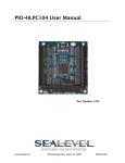
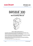
DIO-16.LPCIe Sealevel Systems, Inc. Sealevel.com Phone 864.843.4343 ontents DIO-16.LPCIe .................................................................................................... 1 Item# 8012E ............................................................................................................................ 1 Before You Get Started .......................................................................................................... 4 What‟s Included ...................................................................................................................... 4 Advisory Conventions .......................................................................................................... 4 Optional Items ........................................................................................................................ 5 Introduction ............................................................................................................................... 7 Features .................................................................................................................................... 7 Other Sealevel PCI Digital I/O Products .......................................................................... 8 Software Installation .............................................................................................................. 9 Where to Get Sealevel Software ......................................................................................... 9 Windows Installation............................................................................................................. 9 Guided Software Installation ............................................................................................ 10 Manual Software Installation ............................................................................................ 12 Physical Installation ............................................................................................................. 13 Programming for Windows ............................................................................................... 14 Samples and Utilities .......................................................................................................... 14 Register Layout ..................................................................................................................... 14 Reading the Inputs .............................................................................................................. 14 Reading the Outputs........................................................................................................... 14 Writing the Outputs ............................................................................................................ 14 InterruptS ............................................................................................................................... 15 Input Ports ............................................................................................................................. 15 Input Port Pin Assignments (DB-44 Female) ............................................................... 15 Output Ports (Reed Relay) ................................................................................................. 16 Output Ports (Reed Relay) Pin Assignments (DB-44 Female) ................................. 16 Power and Ground Pin Assignments (DB-44 Female) ............................................... 17 DB-37 Male Pin Assignment ............................................................................................. 18 Technical Specifications ..................................................................................................... 20 Opto-Isolated Input Ports .................................................................................................. 20 Reed Relay Output Ports.................................................................................................... 20 OuTPUt power ....................................................................................................................... 21 Power Requirements ........................................................................................................... 21 Environmental Specifications ........................................................................................... 21 PCB Dimensions ................................................................................................................... 21 Manufacturing ...................................................................................................................... 21 Appendix A - Troubleshooting ......................................................................................... 22 ©Sealevel Systems, Inc. SL9225 – 11/2011 DIO-16.LPCIe Manual 2 Software .................................................................................................................................. 22 Hardware ................................................................................................................................ 23 BIOS .......................................................................................................................................... 24 Device Manager Verification ............................................................................................ 24 Troubleshooting/Verification Utilities for SeaIO Classic Products ....................... 25 SeaIO Device Driver Configuration ................................................................................ 29 Card Selection Configuration ........................................................................................... 29 Appendix B - Handling Instructions ............................................................................... 32 ESD Warnings ........................................................................................................................ 32 Appendix C – Example Circuits ........................................................................................ 33 Input Circuit .......................................................................................................................... 33 Output Circuit ....................................................................................................................... 33 Appendix D – 8012e PCB Drawing .................................................................................. 34 Technical Support ................................................................................................................ 35 Warranty .................................................................................................................................... 36 Warranty Policy ..................................................................................................................... 36 Non-Warranty Repair/Retest ............................................................................................. 36 How to obtain an RMA (Return Merchandise Authorization) ................................. 36 ©Sealevel Systems, Inc. SL9225 – 11/2011 DIO-16.LPCIe Manual 3 The DIO-16.LPCIe is shipped with the following items. If any of these items is missing or damaged, please contact Sealevel for replacement. DIO-16.LPCIe Low Profile PCI Express 8 Reed Relay Output / 8 Isolated Input (3-30V) Item# 8012e ships with Low Profile PCI bracket Item# 8012eS ships with a Standard PCI bracket Sealevel SeaI/O Software CD Warning - The highest level of importance used to stress a condition where damage could result to the product or the user could suffer serious injury. Important – The middle level of importance used to highlight information that might not seem obvious or a situation that could cause the product to fail. Note – The lowest level of importance used to provide background information, additional tips, or other non-critical facts that will not affect the use of the product. High Voltage Warning - USE EXTREME CAUTION! High voltages will be present on the SeaI/O family of products when high voltage is connected. Never handle the printed circuit board when high voltage signals are connected to the board. ©Sealevel Systems, Inc. SL9225 – 11/2011 DIO-16.LPCIe Manual 4 Depending upon your application, you are likely to find one or more of the following items useful for interfacing the DIO-16.LPCIe to real-world signals. All items can be purchased from our website (http://www.sealevel.com) or by calling +1 864843-4343. DB44 Male to DB44 Female, 72” Extension Cable (Item# CA185) The CA185 is a standard DB44M to DB44F extension cable. Extend a DB44 cable or locate a piece of hardware where it is needed with this six foot (72”) cable. The connectors are pinned one-to-one so the cable is compatible with any device or cable with DB44 connectors. The cable is fully shielded against interference and the connectors are molded to provide strain relief. Dual metal thumbscrews secure the cable connections and prevent accidental disconnection. DB44 Male to BD37 Male, 72” Cable (Item# CA206) DB44 Male to DB37 Male Cable, 72 in Length - for 8012. The CA206 is useful for interfacing the DB44 connector on the 8012e to the DB37 connector on the TB02 terminal block. ©Sealevel Systems, Inc. SL9225 – 11/2011 DIO-16.LPCIe Manual 5 Terminal Block – DB37 Male and DB37 Female to 27 Screw Terminals (Item# TB02) The TB02 terminal block can be used to break out serial and digital DB37 connectors to screw terminals for easy field wiring. The terminal block was designed with both DB37 male and female connectors, therefore; it can be used with any DB37 board regardless of the board's port gender. Terminal Block Kit – DB37 Male and DB37 Female to 27 Screw Terminals (Item# TB02-KT) The TB02-KT terminal block can be used to break out serial and digital DB37 connectors to screw terminals for easy field wiring. The terminal block was designed with both DB37 male and female connectors, therefore; it can be used with any DB37 board regardless of the board's port gender. The TB02-KT ships with a RoHS compliant TB02 terminal block, a 6” piece of slotted Snap Track, and two DIN-rail mounting clips. Terminal Block Kit – TB02 + CA206 Cable (Item# KT111) Terminal Block KT111 simplifies field wiring requirements by creating a direct connection between a TB02 terminal block and the 8012 board. The KT111 includes the TB02 terminal block, CA206 cable, ST101 Snap Track and STDIN mounting clips. The Digital I/O Handbook – A Practical Guide to Industrial Input and Output Applications (Item# REF101) Renowned technical author Jon Titus and president and CEO of Sealevel Systems, Tom O'Hanlan, clearly explain real-world digital input/output implementation from both a hardware and software perspective. Whether you are a practicing engineer or a student, The Digital I/O Handbook will provide helpful insight you will use again and again. ©Sealevel Systems, Inc. SL9225 – 11/2011 DIO-16.LPCIe Manual 6 The DIO-16.LPCIe provides 8 optically isolated inputs and 8 reed relay SPST (single pole-single throw) outputs. The inputs protect the PC and other sensitive equipment from spikes and ground loop current that can be generated in industrial environments, while the outputs provide high quality, long life, low current (10 Watt maximum), dry contact switch closures. Reed relays are well suited for low current applications. The relays are normally open, and will close when energized. The board meets the requirements a low profile PCI Express add-in card as defined by the PCISIG in the PCI Express Card Electromechanical Specification Revision 1.1. The DIO-16.LPCIe is designed to be used with Windows Operating Systems. The SeaI/O API (Application Programming Interface) included on the CD shipped with the DIO-16.LPCIe provides a variety of useful high-level function calls implemented as a Windows dynamic link library (.DLL). In addition to the API, SeaI/O includes a device driver, sample code, and utilities to simplify software development. PCI Express x1 compliant Eight optically isolated inputs Eight Reed relay outputs (SPST) Low Profile compliant Power (+5V and +12V) and ground provided on connector SeaI/O Classic software supports Windows Operating Systems ©Sealevel Systems, Inc. SL9225 – 11/2011 DIO-16.LPCIe Manual 7 Product Item# PIO-32.PCI 8010 32 TTL Inputs/Outputs PIO-48.PCI 8005 48 TTL Inputs/Outputs PIO-96.PCI 8009 96 TTL Inputs/Outputs REL-16.PCI 8003 16 Reed Relay Outputs DIO-32.PCI 8004 16 Reed Relay Outputs/16 Opto-isolated Inputs DIO-32.PCI 8004H ISO-16.PCI 8006 ISO-16.PCI 8006H REL-32.PCI 8007 32 Reed Relay Outputs PLC-16.PCI 8011 8 Form C Relay Outputs/8 Opto-isolated Inputs DIO-16.PCI 8012 8 Reed Relay Outputs/8 Opto-isolated Inputs (3-13V) DIO-16.PCI 8012H 8 Reed Relay Outputs/8 Opto-isolated Inputs (10-30V) DIO-32.PCIE 8004e 16 Reed Relay Outputs/16 Opto-isolated Inputs DIO-32.PCIE 8004He ©Sealevel Systems, Inc. SL9225 – 11/2011 Description 16 Reed Relay Outputs/16 Opto-isolated Inputs (10-30V) 16 Opto-isolated Inputs 16 Opto-isolated Inputs (10-30V) 16 Reed Relay Outputs/16 Opto-isolated Inputs (10-30V) DIO-16.LPCIe Manual 8 This section contains helpful information pertaining to the installation of supported Sealevel Systems, Inc. software packages. First, the process of acquiring the software is discussed. Next, the installation is detailed in a step-by-step guide for Windows operating systems. All Sealevel products are shipped with media containing the installers for each software package available. If the media is otherwise unavailable or if desired, the current versions of Sealevel software packages can be obtained from the Sealevel website (see following instructions). If you already have the Sealevel software, proceed to the Windows installation section. 1. Sealevel software for Windows operating systems is available at this link: Software for Windows 2. Choose the link for the desired software package and click on the „Download File‟ link to download the current driver. 3. Proceed to the Manual Software Installation guide for your operating system. Do not connect the hardware until the software has been successfully installed. To install Sealevel software, you must log in as an administrator or have administrator privileges in Windows. ©Sealevel Systems, Inc. SL9225 – 11/2011 DIO-16.LPCIe Manual 9 Insert the Sealevel media into your PC. If the „AutoRun‟ feature is enabled for this media the software will automatically launch. Otherwise, navigate to the root directory of the media and double-click the „autorun.exe‟ application to launch the installation window. Select „Install‟ as demonstrated in the image below. ©Sealevel Systems, Inc. SL9225 – 11/2011 DIO-16.LPCIe Manual 10 Type the part number for your adapter in the text box and press the „Enter‟ key, or click on the drop box to scroll from the listing to select your product. If you installed your hardware prior to loading/installing the software, please click on the Click here if you installed hardware before software link and follow the listed instructions. 1. Click the „Install Drivers‟ button to launch the Installation Wizard. 2. When the InstallShield Wizard‟ window appears, click the „Next‟ button to initiate the software installation. 3. When the „License Agreement‟ window appears, accept the terms and click „Next‟ to continue. You can click the „Print‟ button to print out a copy of the agreement for your records. If you do not accept the terms of the agreement, the installation will stop. 4. When the „Ready to Install the Program‟ window appears, click the „Install‟ button to install the software onto the hard drive of your computer. The files will be automatically installed into the „C:\Program Files‟ folder on your computer. Some versions of Windows will halt the installation and provide you with a dialog box which will ask you for permission for the installer to make changes to your ©Sealevel Systems, Inc. SL9225 – 11/2011 DIO-16.LPCIe Manual 11 computer. Click on the “Allow” button to continue installation of your Sealevel software. 5. The setup file will automatically detect the operating environment and install the proper components. Next follow the information presented on the screens that follow. Once the installation is complete, close the disk installation window. 6. Refer to the Physical Installation section to connect and install your hardware. 1. To install a software package from the Sealevel media, browse the Sealevel Systems media ‟Software‟ directory. For example: Software\SeaIO\Windows\SeaIO Installer.exe 2. If you are using Windows Vista or newer operating systems, right click on the installer executable and choose ‟Run as Administrator‟. If you are using an operating system prior to Windows Vista, double click on the executable to launch the InstallShield and initiate the driver installation. 3. Please refer to step six above in the Guided Software Installation section and follow the remaining installation steps. ©Sealevel Systems, Inc. SL9225 – 11/2011 DIO-16.LPCIe Manual 12 The SeaIevel DIO-16.LPCIe can be installed in any PCIe expansion slot (x1/x4/x16). PCI Express x1 Do not install the adapter in the machine until the product software has been fully installed. To prevent damage from improper handling, please reference Appendix A – ESD Handling Instructions. 1. Turn off PC power. Disconnect the power cord. 2. Remove the PC case cover. 3. Locate an available PCIe slot and remove the blank metal slot cover. 4. Gently insert the PCIe adapter into the slot. Make sure that the adapter is seated properly. 5. Replace the screw you removed for the blank and use it to secure the adapter bracket into the slot. This is required to ensure FCC Part 15 compliance. 6. Replace the cover. 7. Connect the power cord. ©Sealevel Systems, Inc. SL9225 – 11/2011 DIO-16.LPCIe Manual 13 Programming the DIO-16.LPCIe Sealevel‟s SeaI/O software is provided to assist in the development of reliable applications for the Sealevel Systems family of digital I/O adapters. Included on the SeaI/O CD are driver functions for use in accessing the I/O as well as helpful samples and utilities. The SeaI/O API (Application Programmer Interface) provides a variety of useful high-level function calls implemented in a Windows dynamic link library (DLL). The API is defined in the help file (Start/Programs/SeaIO/SeaIO Help) under “Application Programmers Interface”. This help file also includes detailed information dealing with installation / removal of the software and information about latency, logic states, and device configuration. For C language programmers we recommend using the API to access the DIO-16.LPCIe. If you are programming in Visual Basic, using the ActiveX control included with SeaI/O is advised. A variety of sample programs and utilities (both executable and source code) are included with SeaI/O. Further documentation on these samples can be found by selecting “Start/Programs/SeaIO/Sample Application Description”. Information about where the files are physically stored on your disk is also included in this same file. Reference the following sections for more information about the meaning and use of the registers available. Address Mode Mode D7 D6 D5 D4 D3 D2 D1 D0 Base+0 Input Port A RD PAD7 PAD6 PAD5 PAD4 PAD3 PAD2 PAD1 PAD0 Base+2 Output Port C RD/WR PCD7 PCD6 PCD5 PCD4 PCD3 PCD2 PCD1 PCD0 The inputs are active Low. If no voltage is applied across one of the differential inputs it returns a one on that bit. If an AC or DC voltage is applied it returns a zero on that bit. The relay ports return the ones complement of the value that is currently being used to drive the relays. When using the API the actual value is returned not the complement of the value. The output ports are the only ports that can be written. The relays on a standard DIO-16.LPCIe are normally open. To close a relay a one must be written to the appropriate bit. ©Sealevel Systems, Inc. SL9225 – 11/2011 DIO-16.LPCIe Manual 14 Interrupts are not currently supported, however they may be added. Contact Sealevel with your requirements. Port A is an 8 bit input port connected to optically isolated input sensors. Each sensor can be used to interface a voltage input and then sense whether the voltage is on or off. Each sensor is isolated (with respect to a common ground) from every other sensor, and is also isolated with respect to the host PC ground. This means that signals such as low-level AC line voltage, motor servo voltage, and control relay signals can be „sensed‟, or read by the PC, without the risk of damage due to ground loops or ground faults. Each sensor input pair has a current limiting resistor that is used to limit the input current to the opto-isolator. The opto-isolator has two „back-to-back‟ diodes internally. This allows AC or DC signals to be sensed, regardless of polarity. When the applied voltage is high enough to cause the LED in the opto-isolator to turn-on, the output of the opto-isolator goes low (0 volts) and the signal is read as a low logic level (binary 0) by the PC. When the input signal is too low to turn on the opto-isolator, the output goes high and the port bit is read by the PC as a high logic level (binary 1). The input impedance of each isolated input is approximately 1500 ohms (factory default). The opto-isolator requires approximately 2 mA to turn on. The maximum input current is 20 mA. The input circuits are not intended for monitoring 120-volt AC circuits. In addition to being too high a voltage for the circuits, it is dangerous to have that high a voltage on the card. ©Sealevel Systems, Inc. SL9225 – 11/2011 Port A Bit Port A Pins 0 2,40 1 3,41 2 4,36 3 5,37 4 6,38 5 7,42 6 8,43 7 9,44 DIO-16.LPCIe Manual 15 The above diagram is representative of how dry contact inputs (or current / voltage sources) can be monitored by the optically isolated inputs. When switch 1 above is closed, it will allow current to flow from the power source, into pin 3 of the DB-44, through the optocoupler, out pin 41, and back to the power source. If the current flow is between 2 and 20 mA, this input will be read as logic “0”. All the input associated with all open switches will be read as logic “1”. In the diagram above, pins 36-38, and 40-44 are joined, providing a common return path for the optocouplers. In this case, the interconnections are being made on the connector itself. In the DB-37 diagram below the return path is supplied external to the connector. Also for electrical isolation, each input / output pair can be powered from an individual power source with no common present. Reed relays provide very high quality, long life, low current, dry contact switch closures. Reed relays are not suited for high current applications, and can be destroyed by inductive load switching, where a spark occurs across the contacts internally. The relays are normally open, and close when energized. ©Sealevel Systems, Inc. SL9225 – 11/2011 Port C Bit Relay Port C Pins 0 K3 10,28 1 K2 11,29 2 K1 12,30 3 K5 13,31 4 K4 14,32 5 K6 15,33 DIO-16.LPCIe Manual 16 6 K7 16,34 7 K8 17,35 The above diagram is representative of how lights (or other devices) can be controlled by the relay outputs. When relay 2 on the card is closed, it will allow current to flow from the power source, into pin 12 of the DB-44, through the relay, out pin 30, and back to the power source thereby turning the light labeled “2” on. In the diagram above, pins 28-30 and 31-35 of the connector are joined, providing a common return path for the circuit. In this case the interconnections are being made on the connector itself. In the DB-37 diagram below the return path is supplied external to the connector. For electrical isolation, each relay can be wired to an independent isolated circuit. ©Sealevel Systems, Inc. SL9225 – 11/2011 Signal Pin(s) Ground 22,23,24 + 5 Volts 39 + 12 Volts 1 DIO-16.LPCIe Manual 17 Via optional DB-44 Male to DB-37 Male 6‟ cable, Part Number CA206 Bit Port A Pins Port C Pins 0 2,20 10,28 1 3,21 11,29 2 4,22 12,30 3 5,23 13,31 4 6,24 14,32 5 7,25 15,33 6 8,26 16,34 7 9,27 17,35 GND 18,36,37 +12V 1 +5V 19 The diagram is representative of how dry contact inputs (or current / voltage sources) can be monitored by the optically isolated inputs. When switch 1 above is closed, it will allow current to flow from the power source, into pin 3 of the DB-37, through the optocoupler, out pin 21, and back to the power source. If the current flow is between 2 and 20 milliamps, this input will be read as logic “0”. All the input associated with all open switches will be read as logic “1”. ©Sealevel Systems, Inc. SL9225 – 11/2011 DIO-16.LPCIe Manual 18 The above diagram shows that the common path to the optocouplers is provided external to the connector. The common path can be provided at the connector as shown in the DB-44 diagram above. Also for electrical isolation, each input / output pair can be powered from a individual power source with no common present. The diagram above diagram is representative of how lights (or other devices) can be controlled by the relay outputs. When relay 2 on the card is closed, it will allow current to flow from the power source, into pin 12 of the DB-37, through the optocoupler, out pin 30, and back to the power source thereby turning the light labeled “2” on. The above diagram shows the common path to all the relays is provided external to the connector. The common path can be provided at the connector as shown in the DB-44 diagram above. For electrical isolation, each relay can be wired to an independent isolated circuit. ©Sealevel Systems, Inc. SL9225 – 11/2011 DIO-16.LPCIe Manual 19 Turn On Current 2 mA Input Impedance 1500 ohms Resistor Power Max 1W Isolator Diode Drop Max 1.4 VDC Absolute Maximum Input Range 3-35 VDC/VAC Recommended Input Range 3-30 VDC/VAC Isolation 300 VAC RMS Contact Max Power 10 W Switching Voltage Max DC / Peak AC Resistive 60 V Switching Current Max DC / Peak AC Resistive 0.5 A Life Expectancy - Typical (Signal Level 1V, 10mA)* 100 million ops. Relay Max Operate Time, including bounce** 1 ms Relay Max Release Time** 0.2 ms 300 VAC RMS Isolation * Reference Coto Technology Whitepaper “Testing Reed Switches and Relays for Reliability” for more information: http://www.cotorelay.com/Coto_WP__Reliability_Ver_003.pdf ** Minimum hardware timing requirements ©Sealevel Systems, Inc. SL9225 – 11/2011 DIO-16.LPCIe Manual 20 +5VDC Output Current Max 500 mA +12VDC Output Current Max 200 mA PCIe +3.3V Power Rail* PCIe +12V Power Rail* Max: 1.6A (8.1W) Max: 100mA (0.5W) Typ: 0.73A (3.6W) Typ: 50mA (0.3W) *Does not include Output Power pins (+5V/+12V) Specification Temperature Range Humidity Range Operating Storage 0°C – 70°C -35°C – 100°C 10 to 90% R.H. 10 to 90% R.H. Non-Condensing Non-Condensing Length Height (Including Gold fingers) 5.5” (14.0 cm) 2.68” (7.0 cm) All Sealevel Systems printed circuit boards are built to UL 94V0 rating and are 100% electrically tested. These printed circuit boards are solder mask over bare copper. ©Sealevel Systems, Inc. SL9225 – 11/2011 DIO-16.LPCIe Manual 21 Following these simple troubleshooting steps can eliminate most common problems. To install Sealevel Systems Software and hardware in Windows, you must log in as an administrator or have administrator privileges. First, install the software driver and then install the I/O adapter. If the I/O adapter was installed first, complete the „uninstall/reinstall‟ steps. Next, verify that your Sealevel Software is properly installed. This places the required installation files in the correct locations. In Windows it will be located here: Start – All Programs – SeaIO 1. Install the most current Sealevel Software. To obtain the most current software package from Sealevel‟s website, download from here: Sealevel Software Drivers 2. Navigate to the Device Manager (right click on „My Computer‟ and choose „Manage‟, then „Device Manager‟). 3. Look for the SeaI/O Device category and expand it to expose the Sealevel adapter. 4. Right click on the listed adapter and choose „Uninstall‟. 5. Click on „Actions‟ and choose „Scan for hardware changes‟. 6. This will prompt the PC to scan and locate the Sealevel I/O adapter and properly initiate the installation and driver association. ©Sealevel Systems, Inc. SL9225 – 11/2011 DIO-16.LPCIe Manual 22 1. With the system powered down, verify the I/O adapter is seated properly into the slot. 2. If a slot seems unresponsive, power the system down and install the I/O adapter on a different slot on the motherboard. 3. Install the Sealevel Software and I/O adapter in another computer. ©Sealevel Systems, Inc. SL9225 – 11/2011 DIO-16.LPCIe Manual 23 1. PCIe adapters are automatically assigned addressing and IRQs by the system BIOS based on availability. Ensure that available IRQs are set to PCI/PNP (this represents „Plug and Play‟). 2. If hardware installation issues persist, remove other bus level devices from your system to verify if this corrects the problem. Once your Sealevel Software is installed, verify the I/O adapter is properly enumerated. Navigate to the Device Manager for verification and configuration. To access the Device Manager, right click on „My Computer‟ and choose „Manage‟. When the Computer Management menu appears, choose „Device Manager‟. ©Sealevel Systems, Inc. SL9225 – 11/2011 DIO-16.LPCIe Manual 24 These three utilities were designed to verify the functionality of your Sealevel digital I/O adapters. To access these utilities navigate to: Start – All Programs – SeaIO. This utility allows the setting and clearing of individual relays and groups of relays. It also offers timed activation of relays and monitoring of input signals. ©Sealevel Systems, Inc. SL9225 – 11/2011 DIO-16.LPCIe Manual 25 This utility allows the setting and clearing of individual relays. It also offers monitoring of input signals. This utility is a Win32 console application designed for testing all calls to the driver. This utility is very useful for verifying proper SeaIO driver configuration and hardware adapter settings. A main menu offers choices for reading and writing ports, and setting and clearing relays. This utility also demonstrates the use of the NotifyInputChange API call. ©Sealevel Systems, Inc. SL9225 – 11/2011 DIO-16.LPCIe Manual 26 This is an example of a properly enumerated SeaI/O digital I/O adapter in Windows Device Manager. ©Sealevel Systems, Inc. SL9225 – 11/2011 DIO-16.LPCIe Manual 27 Right click on the adapter line item under the SeaI/O Device category and choose „Properties‟. This will show the Properties dialog box, as seen below. This verifies that the SeaI/O digital I/O adapter (8004) is correctly enumerated. To properly configure your digital I/O adapter, please click on the „Card Setup‟ tab and refer to the Configuration section of this manual. ©Sealevel Systems, Inc. SL9225 – 11/2011 DIO-16.LPCIe Manual 28 Configure your SeaI/O adapter device driver settings by navigating to the Device Manger and opening the Properties dialog box for the installed SeaI/O adapter device. Choose the Card Setup tab. The example below shows a SeaI/O 8004 adapter. This parameter sets the time interval for the timer used by the device driver to check the adapter for input state changes. To use, your application must invoke the SeaIO_NotifyInputChange overlapped API device driver call. The default value on installation is 250,000 microseconds (250 milliseconds). Setting the sampling rate below 10,000 microseconds is not recommend as this can heavily tax the host processor. When the Sample Interval parameter is non-zero, the driver to periodically look at the inputs to see when one changes. When an input changes, the driver will complete the previously issued overlapped call. The driver utilizes a recurring timer to notify it to look at the inputs. The period of time (in microseconds) that occurs between passes of the driver looking at the inputs is specified in the Sample Interval box. ©Sealevel Systems, Inc. SL9225 – 11/2011 DIO-16.LPCIe Manual 29 Additional information on Sample Interval can be located in the SeaIO Software Information Help file found here: Start – All Programs – SeaIO – SeaIO Help - Device Configuration. The combo box allows selection of the type of logic that the driver will use: Positive or Negative. The default selection is Positve logic. The original SeaIO API treated devices as if they had active low inputs. This behavior has been revised. The current SeaIO API returns inputs as active high. Legacy SeaIO calls are: SeaIO_ReadReg and SeaIO_WriteReg functions. Their counterparts are: SeaIO_ReadByte, SeaIO_WriteByte, SeaIO_ReadBit, SeaIO_WriteBit, SeaIO_WriteAllOutputs and SeaIO_ReadAllInputs. These functions should be used exclusively by new applications. PIO cards Inputs: If the input threshold voltage has not been met the API returns a 0. If the input threshold voltage has been met the API returns a 1. Outputs: If a 0 is written to the port the output is 0v. If a 1 is written to the port the output is 3-5v. DIO cards Inputs: If the input threshold voltage has not been met the API returns a 0. If the input threshold voltage has been met the API returns a 1. Outputs: If a 0 is written to the port the relay is deenergized. If a 1 is written to the port the relay is energized. PIO cards Inputs: If the threshold voltage has not been met the API returns a 1. If the input threshold voltage has been met the API returns a 0. Outputs: If a 0 is written to the port the output is 3-5v. If a 1 is written to the port the output is 0v. DIO cards Inputs: If the input threshold voltage has not been met the API returns a 1. If the input threshold voltage has been met the API returns a 0. Outputs: If a 0 is written to the port the relay is energized. If a 1 is written to the port the relay is deenergized. ©Sealevel Systems, Inc. SL9225 – 11/2011 DIO-16.LPCIe Manual 30 Additional information for Positive and Negative logic choices can be located in the SeaIO Software Information Help file found here: Start – All Programs – SeaIO – SeaIO Help - Logic States. ©Sealevel Systems, Inc. SL9225 – 11/2011 DIO-16.LPCIe Manual 31 A sudden electrostatic discharge can destroy sensitive components. Proper packaging and grounding rules must therefore be observed. Always take the following precautions: 1. Transport boards and cards in electrostatically secure containers or bags. 2. Keep electrostatically sensitive components in their containers, until they arrive at an electrostatically protected workplace. 3. Only touch electrostatically sensitive components when you are properly grounded. 4. Store electrostatically sensitive components in protective packaging or on anti-static mats. The following measures help to avoid electrostatic damages to the device: 1. Cover workstations with approved antistatic material. Always wear a wrist strap connected to a properly grounded workplace. 2. Use antistatic mats, heel straps, and/or air ionizers for more protection. 3. Always handle electrostatically sensitive components by their edge or by their casing. 4. Avoid contact with pins, leads, or circuitry. 5. Turn off power and input signals before inserting and removing connectors or connecting test equipment. 6. Keep work area free of non-conductive materials such as ordinary plastic assembly aids and Styrofoam. 7. Use field service tools such as cutters, screwdrivers, and vacuum cleaners that are conductive. ©Sealevel Systems, Inc. SL9225 – 11/2011 DIO-16.LPCIe Manual 32 ©Sealevel Systems, Inc. SL9225 – 11/2011 DIO-16.LPCIe Manual 33 ©Sealevel Systems, Inc. SL9225 – 11/2011 DIO-16.LPCIe Manual 34 When calling for technical assistance, please have the device installed and ready to run diagnostics. If possible, have your user manual and current settings ready. The Sealevel website is an excellent resource located at www.sealevel.com. The most current software updates and user manuals are available via our homepage by clicking on the 'Drivers' or 'Manuals' links located under „Technical Support.‟ Manuals and software can also be downloaded from the product page for your device. The FAQ section of our website answers many common questions. Refer to this helpful resource by visiting http://www.sealevel.com/support/. Monday – Friday 8:00 am to 5:00 pm EST Phone: +1 (864) 843-4343 Email: [email protected] ©Sealevel Systems, Inc. SL9225 – 11/2011 DIO-16.LPCIe Manual 35 Sealevel's commitment to providing the best I/O solutions is reflected in the Lifetime Warranty that is standard on all Sealevel manufactured I/O products. Relio™ industrial computers are warranted for a period of two years and the Relio™ R9 family is warranted for a five year period from date of purchase. We are able to offer this warranty due to our control of manufacturing quality and the historically high reliability of our products in the field. Sealevel products are designed and manufactured at its Liberty, South Carolina facility, allowing direct control over product development, production, burn-in and testing. Sealevel achieved ISO-9001:2000 certification in 2002. Sealevel Systems, Inc. (hereafter "Sealevel") warrants that the Product shall conform to and perform in accordance with published technical specifications and shall be free of defects in materials and workmanship for the warranty period. In the event of failure, Sealevel will repair or replace the product at Sealevel's sole discretion. Failures resulting from misapplication or misuse of the Product, failure to adhere to any specifications or instructions, or failure resulting from neglect, abuse, accidents, or acts of nature are not covered under this warranty. Warranty service may be obtained by delivering the Product to Sealevel and providing proof of purchase. Customer agrees to insure the Product or assume the risk of loss or damage in transit, to prepay shipping charges to Sealevel, and to use the original shipping container or equivalent. Warranty is valid only for original purchaser and is not transferable. This warranty applies to Sealevel manufactured Product. Product purchased through Sealevel but manufactured by a third party will retain the original manufacturer's warranty. Products returned due to damage or misuse and Products retested with no problem found are subject to repair/retest charges. A purchase order or credit card number and authorization must be provided in order to obtain an RMA (Return Merchandise Authorization) number prior to returning Product. If you need to return a product for warranty or non-warranty repair, you must first obtain an RMA number. Please contact Sealevel Systems, Inc. Technical Support for assistance: Available Phone Email Monday – Friday, 8:00AM to 5:00PM EST 864-843-4343 [email protected] ©Sealevel Systems, Inc. SL9225 – 11/2011 DIO-16.LPCIe Manual 36