1
AIO110 User Manual
Page 1 of 9
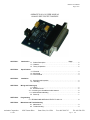
ANIMATICS AIO-110 USER MANUAL
ANALOG INPUT/OUTPUT MODULE
SECTION 1.
Introduction
Page
1.1 Product Description . . . . . . . . . . . . . . . . . . . . . . . . . . . . . . . . . . . . . . . . . . . . . . 2
1.2 Features . . . . . . . . . . . . . . . . . . . . . . . . . . . . . . . . . . . . . . . . . . . . . . . . . . . . . . . .2
1.3 Theory of Operation . . . . . . . . . . . . . . . . . . . . . . . . . . . . . . . . . . . . . . . . . . . . . . .2
SECTION 2.
Specifications
2.1 Electrical . . . . . . . . . . . . . . . . . . . . . . . . . . . . . . . . . . . . . . . . . . . . . . . . . . . . . . . 3
2.2 Mechanical . . . . . . . . . . . . . . . . . . . . . . . . . . . . . . . . . . . . . . . . . . . . . . . . . . . . . 3
2.3 Environmental . . . . . . . . . . . . . . . . . . . . . . . . . . . . . . . . . . . . . . . . . . . . . . . . . . . 3
SECTION 3.
Installation
3.1 Unpacking and Inspection . . . . . . . . . . . . . . . . . . . . . . . . . . . . . . . . . . . . . . . . . 4
3.2 Mounting . . . . . . . . . . . . . . . . . . . . . . . . . . . . . . . . . . . . . . . . . . . . . . . . . . . . . . . 4
SECTION 4.
Wiring and Powering up
4.1 Wiring . . . . . . . . . . . . . . . . . . . . . . . . . . . . . . . . . . . . . . . . . . . . . . . . . . . . . . . . 4
4.2 Connector Pinout . . . . . . . . . . . . . . . . . . . . . . . . . . . . . . . . . . . . . . . . . . . . . . . . . 5
4.3 Connecting to a SmartMotor Anilink Network . . . . . . . . . . . . . . . . . . . . . . . . . . . 6
4.4 Anilink Module Addressing . . . . . . . . . . . . . . . . . . . . . . . . . . . . . . . . . . . . . . . . . 6
4.5 Power Up. . . . . . . . . . . . . . . . . . . . . . . . . . . . . . . . . . . . . . . . . . . . . . . . . . . . . . . 7
SECTION 5.
Programming
5.1 READING AND WRITING OUTPUTS TO AIO-110. . . . . . . . . . . . . . . . . . . . . . . .8
SECTION 6.
Maintainance & Troubleshooting
6.1 Maintenance. . . . . . . . . . . . . . . . . . . . . . . . . . . . . . . . . . . . . . . . . . . . . . . . . . . . . 9
6.2 Trouble Shooting . . . . . . . . . . . . . . . . . . . . . . . . . . . . . . . . . . . . . . . . . . . . . . . . . 9
Animatics Corporation
8-13-2001
3050 Tasman Drive
Santa Clara, CA 95054
Fax: 408-748-8725
Tel: 408-748-8721
Page 1
of 9
AIO110 User Manual
Page 2 of 9
1.0
INTRODUCTION
1.1
PRODUCT DESCRIPTION
AIO-110 is an analog input and output card in the family AIO-1xx (1 series, 10 volt). The card
has four analog input pins: one 0 to 10VDC analog input, Three 0 to 5V analog input
There is one analog output that crates a 0 to +10 VDC on the output pin (10AOUT ) and
creates a scaled output 0 to +5VDC on AOUT output pin. The resolution of the output signal
eight bits of resolution.
Produced as a general purpose peripheral, other similar peripherals have been produced within
the AIO-1XX family of peripherals. Please contact your applications engineer for specifics about
our special products.
1.2
•
•
•
•
•
•
•
FEATURES
One analog output, 0 to +10 VDC range, 8-bit resolution.
Three analog inputs, 0 to +5 VDC range, 8-bit resolution.
Simple plug in operation
Convenient size and mounting, DSUB connector
Direct firmware support under SmartMotor command sets
+5 V DC operation
- Can be drawn from SmartMotor I/O connector.
- Can be drawn directly from AniLink network cable
- Alternate power supply port available
AniLink Network Addressable (3-bit)
- High speed serial communications (100K BPS)
- Multi-drop addressing
1.3
THEORY OF OPERATION
The AIO-110 communicates serially over the AniLink bus with a Animatics SmartMotor or
Animatics controller. The controller can write analog outputs to the AIO-110 module (D/A), or
read analog inputs from it (A/D).
Writing to the AIO-110 is carried out as a three byte string. The first byte of a write command
contains a three bit addressing scheme.
The second byte of a write enables the analog output and performs housekeeping functions, the
third byte contains the output value.
A read is carried out a string of two bytes, and it may cause the AIO-110 to return up to five
bytes since the channels must be converted in order. When a conversion of a channel is started, a
an input voltage sample is stored on the chip, and converted to an eight bit binary code. The
conversion rate is determined by the actual speed of the AniLink bus.
Animatics Corporation
8-13-2001
3050 Tasman Drive
Santa Clara, CA 95054
Fax: 408-748-8725
Tel: 408-748-8721
Page 2
of 9
AIO110 User Manual
Page 3 of 9
SECTION 2:
SPECIFICATIONS
All listed specifications are correct as of the date of printing. See errata for latest details. Any
and all product specifications are subject to change without notice by the manufacturer.
2.1
ELECTRICAL
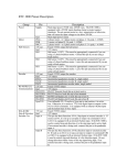
Table 1: Electrical Specifications
Bus DC line voltage
5V DC
Normal Maximum DC current
50 ma
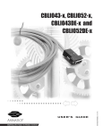
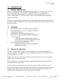
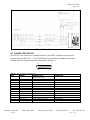
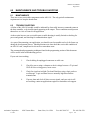
2.2 MECHANICAL
The mechanical drawing of the AIO-110 is presented in Figure 1. The board can be mounted
using #4 screws or other mounting hardware using the four 0.125 in thru holes.
Weight:
Length:
0.8 oz
1.59 in
Height:
Width:
0.625 in
2.00 in
Figure 1: Mounting Layout
2.3
ENVIRONMENTAL
Operating temperature
0°C to 50°C
Storage temperature
Humidity
0 % to 90 % (non-condensing)
Animatics Corporation
8-13-2001
3050 Tasman Drive
Santa Clara, CA 95054
-20°C to 70°C
Fax: 408-748-8725
Tel: 408-748-8721
Page 3
of 9
AIO110 User Manual
Page 4 of 9
3.0
INSTALLATION
3.1
UNPACKING & INSPECTION
Upon receipt of the equipment, carefully inspect to ensure that no damage has occurred during
shipment. If damage is detected, notify the carrier immediately. Equipment should be stored in
its original shipping container until ready for use.
3.2
MOUNTING
The AIO-110 module should be mounted inside a cabinet or suitable enclosure to protect it from
physical and environmental damage. It must be kept free of combustible or flammable materials,
oil vapor, steam, excessive moisture, corrosives and general debris.
Mounting holes for standard 4-40 screws are located in four places on the board. The board can
also be secured using the two threaded 4-40 nuts in the 25-pin DSUB connector. Jack screws are
suggested for this purpose.
4.0
WIRING & POWER UP
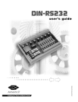
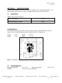
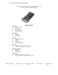
4.1 WIRING
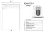
The AIO-110 needs to be supplied with communication and power. Use the SmartMotor to
supply the AIO card with a +5V dc, ground (signal ground), Anilink Data line and Anilink clock
line. These can be wired either from a SmartMotor or Animatics Anilink peripheral. The Figure
2 shows an example wiring scheme. Refer to Table 2 for pinouts.
The AIO-110 can be networked with other AniLink devices using a RJ11-6 connector ( 6 pin
phone jack connector) wired in parallel to pass the +5V,GND, Anilink Data and Anilink Clock
to the additional AniLink modules. The schematic Figure 2.
Longer runs of AniLink cable are possible. Maximum tested runs for the “phone cable” wiring
and RJ11-6 type connectors is about 3 feet. Use of higher efficiency shielded cable and better
connectors will allow much longer runs.
When several AniLink peripherals are connected to the same network, the available controller
power supply may not to maintain operating voltage to the peripherals. If additional power is fed
into one module of an AniLink network that power will be distributed to the other modules over
the +5V line of the AniLink network.
Animatics Corporation
8-13-2001
3050 Tasman Drive
Santa Clara, CA 95054
Fax: 408-748-8725
Tel: 408-748-8721
Page 4
of 9
AIO110 User Manual
Page 5 of 9
Figure 2: Wiring Scheme
4.2 CONNECTOR PINOUTS
The AIO110’s I/O connector is a standard female 25 pin DSUB. Peripheral systems can be
powered from the AIO-110’s + 5 VDC and GND up to the maximum available current on the
AniLink network. The pin assignment is listed below in Figure 2.
13
25
1
14
TABLE 2: AIO-110 Pinout, 25 Pin Connector
PIN #
SIGNAL
DESCRIPTION
1
Reserved, do not use
2
INPUT#2
Analog Input #2 (0 to +5V)
3
INPUT#3
Analog Input #3 (0 to +5V)
4
INPUT#4
Analog Input #4 (0 to +5V)
5
ANILINK DATA
AniLink peripheral bus data line
6
ANILINK DATA
AniLink peripheral bus data line
7
ANILINK CLOCK
AniLink peripheral bus clock line
8
ANILINK CLOCK
AniLink peripheral bus clock line
9
INPUT#1 (10V)
Analog Input#1 (0 to +10V)
10
5V AOUT
Analog output (0 to +5V)
11
+5V in
+5V DC in
12
+5V in
+5V DC in
13
10V AOUT
Analog Output (0 to +10V)
14 TO 25
GND
GROUND
Animatics Corporation
8-13-2001
3050 Tasman Drive
Santa Clara, CA 95054
COMMENTS
8 bit resolution
8 bit resolution
8 bit resolution
Connect to SmartMotor i/o pin E
Tied to pin 5 on board
Connect to SmartMotor i/o pin F
Tied to pin 7 on board
8 bit resolution
8 bit resolution (1/2 voltage of pin13)
Pin 11 & 12 Tied on board
Pin 11 & 12 Tied on board
8 bit resolution
All GND are tied together on board
Fax: 408-748-8725
Tel: 408-748-8721
Page 5
of 9
AIO110 User Manual
Page 6 of 9
The AOUT and 10VAOUT output a voltage when an analog output command is issued. The pins
are connected thru a resistor network thus “5V AOUT” pin is ½ the voltage of the “10VAOUT”
pin. To connect the AIO-110 card to other Anilink devices with a double RJ11-6 connector for
networking Anilnk devices, make a cable assembly to match the pin out is provided below.
1
6
1
6
TABLE 3: Pinout, RJ11 Anilink Network Connector
PIN
SIGNAL
DESCRIPTION
Reserved, do not use
1
2
GND
To SmartMotor signal ground
3
+5V DC
AniLink Power from SmartMotor (limited to about 150 mA)
4
AniLink Clock
AniLink Clock (I/O pin E )
5
AniLink Data
AniLink Data (I/O pin F )
6
Reserved, do not use
4.3 CONNECTING TO A SMARTMOTOR ANILINK NETWORK
Each AIO-110 has a hardware selectable peripheral address. The factory default setting on the
card is address “A”. If you are using multiple-AniLink peripherals on one AniLink network, each
device must have a different address to function properly.
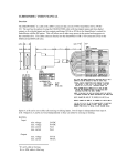
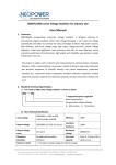
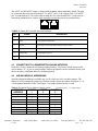
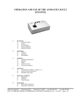
4.4 ANILINK MODULE ADDRESSING
AniLink peripherals addresses available are A to H, which are set by set three jumpers. The
address is set by inserting the jumpers to electrical conduct across the column of jumpers 1, 2 or
3 in the pattern detailed in Table 4 and Figure 3 for jumper location on the i/o card.
Table 4: Peripheral Device Address Jumper setting
(√= jumper in place
MODULE
JUMPER
JUMPER
JUMPER
ADDRESS
1
2
3
A
O
O
O
B
O
O
√
C
O
O
√
D
O
√
√
E
O
O
√
F
O
√
√
G
O
√
√
H
√
√
√
Animatics Corporation
8-13-2001
3050 Tasman Drive
Santa Clara, CA 95054
O = jumper absent)
Fax: 408-748-8725
Tel: 408-748-8721
Page 6
of 9
AIO110 User Manual
Page 7 of 9
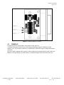
Figure 3: Address Jumpers Location
4.5
POWER-UP
No particular power up procedure is necessary for the AIO-110.
A checkout procedure can be derived from the programming examples found later in this
manual. Use a 5 K pot and a voltmeter or oscilloscope to check the expected ranges and returns
if desired.
Be sure to apply common safety practices when working on any motion based system: make sure
that there is no possibility of personal injury or machine damage before first time power up.
Animatics Corporation
8-13-2001
3050 Tasman Drive
Santa Clara, CA 95054
Fax: 408-748-8725
Tel: 408-748-8721
Page 7
of 9
AIO110 User Manual
Page 8 of 9
SECTION 5.0
PROGRAMMING
5.1 READING AND WRITING OUTPUTS TO AIO-110
The SmartMotor has direct command software support for the AIO-110 module and can read
four analog inputs and write one analog output. To read and write to the AIO-110 issue the
commands in the format described in the table below:
COMMAND FORMAT
AIN{module address}{ input number}
AOUT{module address}, {output value}
COMMENTS
Read analog input from input pin from module .
Module Address Range: A to H (default is address A)
Input Number Range:
1 to 4
Outputs an analog voltage to a 8 bit digital D/A converter to turn on
analog output on both 10VAOUT pin and AOUT pin.
Module Address Range:
A to H (factory setting is address A)
Output Value Range:
0 to 255 , where 255 is maximum voltage, 0 is zero volts.
Voltage Output range.
“10V AOUT” pin: 0 to +10 volt DC.
“AOUT” pin:
0 to +5 volt DC.
5.2 PROGRAMMING EXAMPLES
1) READING INPUT:
aa=AINA1 ‘read Analog Input from address A, input#1, store to variable aa.
bb=AINA2 ‘read analog input,address A, input number 2 and store to bb.
cc=AINA3 ‘read analog input,address A, input number 3 and store to cc.
dd=AINA4 ‘read analog input,address A, input number 4 and store to dd.
f=AINB1
‘read Analog Input from address B, input#1, store to variable f.
g=AINB2
‘read analog input,address B, input number 2 and store to g.
h=AINB3
‘read analog input,address B, input number 3 and store to h.
i=AINB4
‘read analog input,address B, input number 4 and store to i.
2) WRITING OUTPUT:
AOUTA,255
‘Turn on Analog OUTput,address A,output value 255(max voltage)
‘
to 10V AOUT pin and AOUT pin.
ee=128
AOUTA,ee
‘Analog Output, address A, output value ee=128.
AOUTE,255
j=128
AOUTE,j
‘Turn on Analog OUTput,address E,output value 255(max voltage)
‘
to 10V AOUT pin and AOUT pin.
‘Analog Output, address E, output value j=128.
3) MATH/LOGIC OPERATIONS ON INPUTS:
The inputs can be used in direct math and logical operations that are
permitted by the SmartMotor command set. Refer to SmartMotor Manual and
addendum for math and logic capabilites.
bbb=AINA2-64
IF AINA4>=128
AOUTA,bbb
ENDIF
Animatics Corporation
8-13-2001
‘ math operation on an analog input #2
‘ logical comparison on analog input #4
3050 Tasman Drive
Santa Clara, CA 95054
Fax: 408-748-8725
Tel: 408-748-8721
Page 8
of 9
AIO110 User Manual
Page 9 of 9
6.0
MAINTAINENCE AND TROUBLE SHOOTING
6.1
MAINTAINENCE
There are no user serviceable components on the AIO-110. The only periodic maintenance
requirement is to keep the board clean.
6.2
TROUBLE SHOOTING
A failure of the AIO-110 module would be indicated by observably incorrect command returns at
the host controller, or by invalid signals appearing at the output. These conditions would present
themselves as a loss of control in an application.
As these units have no user serviceable parts, trouble shooting is usually limited to checking for
power and ground, and checking for communications signal.
As a part of documenting your application, you should record acceptable test levels for future use
during the development process. Should questions arise later about the serviceable condition of
an AIO-110 card, comparison levels can be a tremendous asset.
The commands and programming techniques found in the programming section of this document
will be useful in the troubleshooting process.
If your unit is not working:
Animatics Corporation
8-13-2001
1.
Check cabling for unplugged connectors or cable cuts.
2.
Check for power using a voltmeter to check voltage between +5V pin and
GND. If not receiving power, locate cause.
3.
Check for signal on AniLink Clock and Data lines using a logic probe or
oscilloscope. Logic and Data lines are normally high between data
transmissions.
4.
If power, data and clock all show correct signals, and your unit is still
not working, contact an applications engineer at Animatics tech support .
3050 Tasman Drive
Santa Clara, CA 95054
Fax: 408-748-8725
Tel: 408-748-8721
Page 9
of 9
![Les besoins des plantes [expériences] séq2](http://vs1.manualzilla.com/store/data/006425426_1-d260fe3404863812e90a2af157c2db5a-150x150.png)