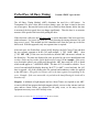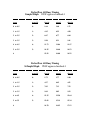
1
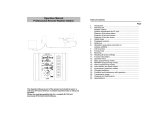
Official Speed Control of USA WaterSki & U.S. National’s
Official Speed Control of the Pro Tour, Masters, U.S. Open, Malibu
Open
DigitalPro
By PerfectPass
Version Xy 6.4
ST300 Paddlewheel
November 2002
Information or assistance:
PerfectPass Control Systems Inc.
218 Wright Avenue
Burnside Industrial Park
Dartmouth, Nova Scotia
CANADA B3B 1R6
By phone
(902) 468-2150
By fax
(902) 468-8837
By email [email protected]
TABLE OF CONTENTS
Page
Number
Section 1
- Initial Set Up
1
Section 2
- Slalom Set Up
- Driving Slalom Skier’s
3
4
Section 3
- Jump Set Up
- Driving Jump Skier’s
8
10
Section 4
- Trick Mode
13
Section 5
- Wakeboard Mode
15
Section 6
- The Display/Moving Through the Menu
Hour Meter/Lake Temp/Software Confirmation
17
Section 7
- Integrated Timing/Smart Timer Sensor
19
Section 8
- Trouble Shooting/General Information
21
APPENDIX
Magnet Test Mode/Device Test
Testing Magnet Strength and Polarity
Voltage Test
Servo Motor Test
Jump Switch Test
Fall Button Test
Slalom and Jump Settings, Tournament Mode (Slalom)
All Ball Timing Information
Connecting Jump Switch
Installation Instructions
USER’S GUIDE
Section 1. INITIAL SET UP
(1) INITIAL SET UP (The display will guide you through this set up)
(Read slowly and carefully)
Your new PerfectPass system must now complete a short set up procedure to familiarize
itself with your particular boat and engine.
Turn the key to on and power up the system. You will note a short delay of a few
seconds before the display becomes active. Check to make sure there is power to the
servo motor. When powered up the black knob should be difficult to turn.
Step (1)
Initial HRS 000. To activate the hour meter feature, set the number of
hours on your boat by pressing the Up Key. If new, leave at 0, Press
menu to proceed.
Engine Selection. On some systems you will be asked to select the
engine in your boat. It will appear as [ 6.0 / 8.1 ^ = Yes ]. This means if
you have an optional 6 or 8.l Litre engine, press Up. For all others, press
Down.
Step (2)
Turn boat engine on. After a few seconds the display will show [ Read in
Mph ^ = Yes ]. It is asking you if you would like the display to operate
in
m.p.h. If you do confirm so by pressing the up key. If you want
k.p.h.
press the down key. (We have selected m.p.h. for
illustration purposes)
The display will now ask if you are a wakeboard only user. If you only
intend to use the system for wakeboarding, press the up key. For three
event skiing and wakeboarding, press the down key. [ Wakeboard only ^
= Y ] (You can switch back & forth later if you wish. See General Information – Page
23).
If you selected wakeboard only, you are ready to use the system. (see
wakeboard section in manual)
The display will now read [ Adjust by 2 mph ^ = Yes ]. If you want
your system to adjust in normal 2 mph adjustments press up. (ie: 34.2 to
36 mph). For 1 kph adjustments press the down key. (Adjust by 2 is
recommended).
Step (3)
The display will now ask you what the total crew weight is:
1
[ CREW ADJ 000 ]. Dial in the approximate total weight of the driver
and crew (in pounds). Press menu key to proceed. (This is for use in the
slalom & jump modes only)
Note: If running in metric, pounds = 2.2 kilograms.(ie: double the kilogram weight and
add 10%. 70 k = 140 + 10% is 154 pounds.)
Step (4)
The display will now move into the slalom mode, which will appear
as:
(1) skier adjust
(2) event mode, slalom
(skier weight)
[ 00 r
00 34.2 ]
(3) engine rpm
(4) set speed
Screen explanation
1.
2.
3.
4.
Skier adjust - leave at 00, details later
Event mode, r means rpm based slalom (Class R Time Charts)
Actual rpm of the engine (digital tachometer)
Set speed is the speed you wish to run and as shown is set at 34.2 mph (55 kph), this
will convert to a digital speedometer as the boat speed is increased.
At this point you may wish to scroll through the menu while sitting still and get
comfortable with the various features and with moving between modes before proceeding.
If you are not using your system for slalom, you can ignore this section and move direct
to trick or wakeboard mode.
If you wish to move from slalom to another mode, press menu key until [ Slalom ^ =
jmp ] appears. This means press the up key to move from Slalom to jump mode. Keep
pressing up key until the desired mode is found (Jump, Trick, Wakeboard, Magnet Test).
Note: Always press the “ON” or “OFF” key when boat is in neutral. When ON,
system will automatically engage when set speed is reached. To disengage system, pull
back throttle to the idle or neutral position.
2
Section 2.
SLALOM
Setting Baselines / Speedometer Calibration
Make sure the skier adjust value remains at 0 during this procedure.
(A slalom Course is required for this important procedure)
Although the internal PerfectPass system and speedometer is set at the factory, accurate
RPM values to run these speeds on your boat must be selected. (Ie: Baseline values)
RPM Baseline values must be set for each of the speeds you intend to use. In slalom and
jump modes the system controls the boat speed based on RPM, and therefore it is
necessary to set up the right r.p.m. value to accurately run each speed. This is
commonly called “ the baseline rpm value.”
Understanding how it works? : In slalom the system controls via RPM. Since the system does
not know how many RPM it takes to run your boat at each speed it is necessary to set up a RPM baseline
value to run each official speed. This is done without a skier. When properly set up your boat should run
near actual times at each speed without a skier. When towing skiers you will add a “skier adjust value“ to
compensate for the weight and pull of the skier. (this is discussed later.)
----------------------------------------------------------(Skier Adjust)
skier weight tach
set speed
[ 00 r 3380
34.2 ]
Read Carefully!
The display should now be in slalom mode as shown above. The 34.2 represents the
desired speed (set speed). This set speed can only be changed by pressing the menu key
twice, which will take you to Speed Adjust. You may wish to set up all of the official
slalom speeds (26.7, 28.6, 30.4, 32.3, 34.2, 36) or just the ones you use most.(at this
point we recommend just the ones you use most). Now it is time to set the proper
baseline RPM required of your engine to run the speeds you wish to use without a skier,
therefore the skier adjust should be set to 00. PerfectPass has been loaded with a default
baseline R.P.M. for each speed (an estimate) and now we are going to adjust it so it is
accurate for your Boat. Let’s assume you want to set up 34.2 and 36 m.p.h. We will
start with 34.2.
Without a skier, drive your boat through the slalom course timing the pass using the
PerfectPass hand timer or Smart Timer magnetic sensor if you have magnets in your
course. Drive as you normally would by bringing the boat up to or beyond the target
speed well prior to the entrance gates to engage system. Once the default baseline
R.P.M. is reached for that speed the system will take over automatically and will indicate
3
so by underlining some of the data on the display and there is an audible beep from the
display.
You must time the first and second segments as you pass through the course (Entrance
Gate, Ball 3 & Exit Gate) and these times will be displayed instantly as you exit the
course. (Also for a brief second the display will show you how many RPM it will take to
get an actual time. This will appear as { + 40 ADJ }. In this example it is suggesting
the speed error was 40 RPM. Bring the boat to neutral, review the times and use the
“Quick Calibrate” feature to automatically adjust the baseline value.
Quick Calibrate - After the times are displayed, press menu key several times until
[ recalibrate ^ = Y ] appears and press up to confirm recalibration. It will then show
{ + 40 = >RPM @ ^=Y }
This means press up and the 40 rpm will automatically be added to the baseline value.
Your baseline value has now been permanently set for 34.2 mph and will be retained in
the system.
Now you must complete this same procedure for 36 m.p.h. and all other speeds you wish
to set up. Change the set speed by going into the Speed Adjust feature by pressing the
menu key twice and change the speed to 36 using the up key. Once again, drive up to 36
mph or beyond to engage system. Time the boat through the course and after the times
are displayed go into “Recalibrate” in the menu.
Speeds Under 24 MPH – If you select a slalom speed of 23 mph or less, the system changes from RPM
based to speed based using the paddlewheel. When you are setting baselines at these slow speeds, once
you get times go, to “Recalibrate ^ = Yes” in the menu. (Only use the “Speedo Calibrate” feature as
discussed in following paragraph).
Cannot get valid times while running baselines? - Whether you are running in the speed based mode
(under 24 mph ) or the standard rpm slalom speeds, if the timer is “timing out” prior to the end of the
course the boat speed may be too far off of actual. In this case, the “quick calibrate” will not work. You
must do the following to manually adjust the speed so it is closer to actual so “quick calibrate” can be
used.
RPM Speeds (24.9 – 36 mph) Go into the menu to [RPM @ ] and manually adjust the baseline setting.
(Remember, 100 rpm is about 1 mph). Use menu key to return to slalom screen and run timing pass
again.
Speeds under 23.0 mph – To speed up or slow down the operating speed, go into the menu and find
[Speedo Calibrate] and manually adjust up or down the speed. Use menu key to return to main screen and
run timing pass again.
Driving Slalom Skiers
Skier weight
{ 165 r
tach
3380 34.2 }
set speed (converts to digital speedometer)
Once your baselines have been set, you are ready to tow skiers. Turn control ON (this should
always be done in neutral).
4
Step 1 – Go to “Crew Adjust” in the menu and dial in the total weight of driver and crew.
(Only required when crew weight has changed).
Step 2 – Select the desired Speed by going into menu to “Speed Adjust”.
Step 3 – Enter the Skier’s Weight. This is done using the up and down keys when the
main slalom screen is on the display. [ 175 r 00 34.2 ] The 175 represents the
skier’s weight.
(Expert skiers will generally require their weight to get a good time, while novice skiers will likely use a
lower value).
Pull the skier up normally and when the boat speed reaches the desired set speed you will
hear an audible beep as it takes control. (Data on the screen will also become underlined to confirm
engagement).
If you are timing (using Smart Timer or manually timing using the PerfectPass Hand Timer) the
timer on the screen will start as you enter the course. At the end of the course, the
display will show the times and will make a suggested change to the skier weight if the
times were not actual. It will appear as [ + 20 ADJ ]. In this case, it is suggesting you
increase the skier’s weight by 20 for the next pass. (This change will add 20 rpm onto
boat speed).
(If times are significantly off, check baseline value without a skier)
Timing – At the end of each timed pass, the first segment time (time to ball 3) and the
full course time will be briefly shown as [ 7.13 16.95 OK ] The OK means the time
was within tolerance. The screen will then flip over and display the first and second
segment times followed by the error and suggested RPM change for the next pass. At
any point, you can press the Menu Key to review the times prior to the next pass. (To
quickly clear times and return to main screen, press the Up Key).
Class R < > C Times – You can now run in either Class C or Class R times. To select,
while in slalom mode, press the off key, then up and down keys together. The screen will
indicate which times are recognized with either r or C on the main screen:
[ 00 C 3380 34.2 ]
In this example, Class C times will be displayed.
Class C
Digital Speed Readout – The digital speedometer on the screen is for information only
in slalom mode. If you feel it is not reading accurately, go into “Recalibrate” in the menu
after any timed pass and recalibrate. (You can only recalibrate speedometer in a course
using times).
Speeds 23 MPH or Lower – If you are towing at these speeds, the system will control
via speed instead of RPM. You must go into menu and select “New Skier” and enter their
weight and KX/PX preferences. If future passes are at faster speeds, the system will
seamlessly switch over to RPM mode.
5
Wind Adjust - If you are driving in a wind, most drivers will increase the skier adjust
(skier weight) a little when driving into the wind and lower the skier adjust when running
down wind to compensate.
The alternative is to use the “Wind Adjust” feature found in the slalom menu, which
allows you to set an rpm value for wind strength. It will appear as { WIND ADJ 000 }
Set a value such as 20 and press menu to continue. It will then ask if the next pass is a
head wind (h) or a tailwind (t). The wind direction request will appear after every pass.
If you do not wish to use wind adjust, always reset the wind adjust value to 0.
Fall Button (Competition Use) - If you are not using “All Ball Timing” you will
require the Fall Button in a tournament situation. Because the slalom mode is designed to
hold a constant r.p.m. value, the boat will pick up speed when a skier falls or stops skiing
which may result in a fast time. In tournaments, the boat judge must push the remote Fall
Button.
The general rule is this:
1.
If the skier has fallen and lost the handle the fall button should be immediately
pushed once.
2.
If the skier has not fallen but has stopped cutting, the remote fall button should be
pushed once, and pushed again once the skier has returned to the wake behind the
boat. (Total two presses). In either case, the system will adjust the RPM of the
engine to produce a good time.
At the end of a pass where the Fall Button has been pressed following the times, the display
will show “Fall Button 2” for example to confirm the Fall button was pressed two times.
(If you are not using your boats for tournaments, we recommend the Fall Button be
disconnected)
More Throttle – If you see the “#” sign after the speed pop up on the screen, the
system is indicating it needs more manual throttle in order to maintain the speed. In this
case just move the manual throttle forward a little.
Pop Up Metric Converter - Since skier weight must be entered in pounds, the system
will now easily convert for you from kilograms to pounds. To access, press the Menu
and ∨ key together. Enter skier weight in pounds and the Pop Up Metric Converter will
calculate the weight in kilograms. Then press the menu key to revert back to previous
mode.
Crew Weight Calculator - The system will add the weight of the individual crew
members. Simply go to “Crew Weight” in the menu, then press the ∨ and ^ keys
together, enter the weight of crew member #1, press menu and do the same for crew
member #2. The system will total the weight automatically.
6
7
Smart Timer False Triggered ? – The Smart Timer is sensitive and will false trigger
outside the course on waves, etc. To avoid false triggering, always slow the boat slightly
to disengage the system after exiting the course between passes. The system will not
false trigger if it is not engaged. (In the event the Timer does trigger before the course,
press the Up Key to reset Timer).
Optional Slalom Switch – If you have a rope switch, refer to detailed instructions sent
with switch. The switch is beneficial to “short line skiers”. For full details, please
contact PerfectPass, or log on to www.perfectpass.com.
Adjustable Settings - For details on adjustable settings, see appendix at rear of Manual.
8
Section 3.
JUMP EVENT
JUMP MODE ( Establishing Baseline RPM Values)
WARNING: (Timing must be used in Jump Event and a proper two segment jump
course is required for system to work properly. Do not use PerfectPass in jump mode
without a proper course, integrated timing and experienced operators). Because the
counter cut pull and cut to the ramp are different, you must have timing activated and
running as the boat heads towards the ramp.
The jump mode is RPM based and therefore baseline values must be established just as in
slalom mode. Setting the jump baseline values must be done in a proper two segment
jump course. Segment balance letter must be set at A for this process.
The first step is to go to the jump mode by pressing the menu button until “ SLALOM
^ = jmp ” appears. It is asking if you want to move from the slalom mode to another
event and if so press the up key. Press the up key once and “ JUMP ^ = Trick ” will
appear. Now you are in the jump mode. The screen will appear as:
event mode
segment balance (only for jump switch users)
JUMP A ^
00
35.4
tachometer
set speed, converts to digital speedometer
The first step is to dial in the weight of the crew by going to crew adjust. (If it is the same
as when you set up slalom it will retain that weight.)
You can set baseline rpm values for all of the official jump speeds ( 28, 29.8, 31.7, 35.4)
or just the ones you use regularly. (You require a proper 2 segment jump course) Let’s
assume you wish to set up 35.4 mph (57 kph) Up the set speed on the display to 35.4
by pressing menu key twice which will take you to “Speed Adjust”. Now bring the boat
smoothly up to the set speed to engage the system. (The system engages as soon as the
default RPM baseline value is reached and the data will become underlined as well as an
audible beep) Enter the jump course and time both segments with Smart Timer. As you
exit the course the times will be displayed and then the difference from actuals. If they
are not in tolerance or close to actual then the baseline RPM values will require
adjustment. The easiest way to do this in jump mode is to go to Recalibrate by pressing
the menu key until you see “ Recal 35.4 ^ = yes”. Press the up key to recalibrate. This
will calibrate the digital speedometer and then the system will suggest how much the
9
baseline value should be adjusted. It will appear as “ + 60 ADJ ” In this example it is
suggesting your baseline should be increased by 60 rpm. The system will then ask if you
want it to automatically adjust the baseline as suggested. It will appear as:
“+60 =>RPM@^=Y” Confirm you want the auto adjustment by pressing the up key.
Now engage system and time boat again. If the times are still not close enough, repeat
above steps until accurate.
Tip: Typically, a 10 rpm change will change the full course time by .02 seconds.
Tip: You can recalibrate after any successful pass if you feel your digital speed readout is
not reading accurately. By recalibrating, PerfectPass will internally use the times
measured to correctly adjust the speed in the computer to display the actual speed.
If you wish to set up baseline rpm values for other speeds, ie.31.7, (51 kph) change the
set speed and repeat the above steps.
IMPORTANT NOTE: The segment balance letter will appear on the screen and is
factory set at A. This is only used with optional jump sensor and should be left at A if the
jump sensor is not being used.
Timing – Ideally, magnets will be installed on both sides of the jump course (6
magnets) and two Smart Timer sensors are used. (One sensor on each side of
boat).
Crew Weight Calculator - The crew weight calculator can be accessed in Jump Mode
as well as by pressing the (+ and -) keys together when Crew Adj is on the screen.
Pop Up Metric Converter
KG <> LB
M <> FT
Simply press the menu and v keys together.
JUMP SWITCH - For details on the optional Jump Switch (Slalom Switch) contact
PerfectPass or log on to www.perfectpass.com .
10
WARNING – Using the Jump program with Jump Switch is for experienced drivers and skiers only.
Please read carefully prior to operating. The pull is very aggressive and designed for tournament water
skiers only. You MUST have integrated timing and a proper jump course for system to operate properly)
Using Xy 6.4 SoftwareUsing Xy 6 Software
JUMP DRIVING
letter
[ JUMP A^ 00 35.4 ]
tach
set speed
Assuming the baseline settings have been accurately set, you are now ready to tow skiers.
The first step is to go into menu to start a new jumper. It will appear as:
[ V = S2% ^= NEW JMPR ]
Press the up key and select speed, then dial in the skiers weight (pounds), press menu and
dial in the skiers typical distance jumped in feet. Once this is done press menu and the
system will ask [ Fast 2nd Seg ^ = Y ]. If you wish to run the faster second segment
times, press the Up key. If you want the system to simply return to baseline (RTB),
press the Down key. The display will now return to the main screen with a Jump Letter
selected. (This can be changed by pressing the up & down keys.) This letter represents
how much throttle will be applied once the Rope Switch is closed as the skier pulls. (The
higher the letter, the more aggressive the pull)
The key to a good pull and good times is to get the correct Jump Letter. If the pull to the
ramp is solid and the first segment time is good, you know the Jump Letter is OK. If the
time on the 1st segment was slow, you will require a higher letter on the next pass and vice
versa.
ADJUSTABLE PARAMETERSADJUSTABLE PARAMETERS
There are a number of adjustments that can be made (on the fly and between passes) to
adjust the timing and pull characteristics).
(Access by turning control off, then press up & down keys together. S2% and S2 Fine can be adjusted on
the main screen)
Typical Values
S2% Faster
60
(higher number, faster 2nd segment time)
CT
175
(higher number, longer throttle application)
S2 Fine
0
(higher number, speeds up 2nd segment only)
S2% - (Second Segment) This is a percent of the Jump Letter RPM that is applied
once the boat enters the 2nd segment. Under IWSF rules, the boat is permitted to speed up
in the 2nd segment. The higher the number, the more the boat will accelerate.
Example: If the 1st segment times are good, but the 2nd is a little slow, you would raise the
number.
11
CT – (Countercut Time) – The maximum length of time the system will throttle once
the skier pulls and closes the switch on the countercut. Example: a value of 175 is 1.75
seconds. In a head wind you may want a longer pull so you could move it to 200 – 220.
(2 – 2.2 seconds)
S2 Fine – This adjustment allows the driver to effectively fine adjust the 2nd segment
only. It comes set at 0, which means a neutral effect. A number such as 30 would
increase the 2nd segment by 30 rpm. Example: A jumper that does not cut and does not
fully activate the switch may require extra rpm in the 2nd segment to keep the 2nd in
tolerance.
RPM Adjust – RPM Adjust is found in the normal menu screen and appears as
[ ADJUST RPM ]. RPM adjust allows the driver to increase or decrease the overall
times (1st & 2ng segment) by putting in an rpm value.
Example: If the times are running consistently slow on both segments, you could add a
value such as 20 rpm and the speed will be increased. You may wish to do this for a
particular skier (a heavy puller) or for a number of skiers if the times are drifting in a
certain direction. When a value has been entered the screen will add a “+” sign on the
display to remind the driver this feature is in effect. [ JMP + R 35.4 ].
Return to Baseline (RTB) – If you selected return to baseline instead of the faster
second segment, the boat speed will immediately go to the baseline value as boat enters
the second segment. If you have a skier using the switch with a value of J or higher, you
can enter an S2 value which is a % of switch driven RPM. A setting above 0 will speed
up boat in second segment if required to balance times. (This is similar to S2% used when
the faster second segment is selected).
(If skier does not trigger switch or has a letter less than J, S2 fine should be used to speed
up second segment).
Important Note: If the timer is triggered prior to entering the course, it must be reset by
pressing the UP key. Failure to reset will result in an improper pull to the ramp.
Other features:
Faster 2nd Segment – If you selected to run the faster 2nd segment, the screen will add
the icon “ ^ “ next to the letter as a reminder to the driver that you are running the faster
times. [ JUMP R^ 35.4 ].
V = S2% ^ = New Jumper – At any point the driver wishes to tweak the S2% or S2
Fine, simply go into menu and press the down key.
12
[S2% Faster 060 ] this will appear first. Press menu and [ S2fine RPM 000 ] will
appear.
Actual Times – At ant time the driver selects faster 2nd or return to baseline, the display
will briefly show the actual times before resetting automatically.
Class R < > Class C Times – You can select the system to run either. Press control off,
then up and down keys together.
13
Section 4.
TRICK MODE
The trick mode is controlled via the speed signal from the paddle wheel. (RPM values are not
used)
Trick speeds should be reasonably accurate from your paddle wheel out of the box. If
they need some adjustment go to “calibrate speedo” and increase or decrease the speed so
it matches your other speedometer.
(To check the accuracy, engage the system in the slalom course using a stop watch, it will
take 34 seconds at 17 mph (27.4 kph) to run the entire slalom course.
Alternatively, a hand held GPS is an easy way to confirm speed.)
The trick screen will appear as:
set speed
{ TRICK
17.0 0.0 }
actual speed
Calibrate Digital Speedometer – (Calibrate Speedo) – If your digital speedometer is
not accurate, you can go into the “calibrate speedo” feature in the menu. Example: If you
are set at 17 mph, but the analog speedometer or GPS is reading 18 mph, you would have
“calibrate speedo” on the screen and press the down key until the boat speed drops to 17
mph so the PerfectPass matches the GPS on other speedo.
If you calibrate speedo on trick speed, ie. 17 mph, all other trick and wakeboard speeds
are also corrected.
Driving Tricks is relatively easy. Turn control on, simply select the desired speed and
drive smoothly to the set point so PerfectPass can seamlessly take over. (if you accelerate
aggressively past the set speed, it will take the system several seconds to lock in the speed)
You should keep your hand on the throttle to ensure it does not pull back and disengage
the system. If you see the “#” sign on the screen, this indicates the system needs a little
more manual throttle.
If the skier falls, pull back on the throttle to disengage system. Slowly return to skier and
pull them back up again. System will take over automatically once set speed in reached.
When you are finished with the speed control, go to neutral and press the OFF key.
KD – This adjustable parameter controls the “firmness of the Pull”. It can be accessed by
turning control Off, then press the Up & Down Keys together. Typical values are 14 –
18. Press menu and NN will appear.
14
NN (Adjustable Paddle Filter Factor) – NN is set at 100 and represents the “Filter
Factor” of the paddle. The higher the value, the more speed samples are taken from the
Paddle prior to speed adjustment. It is rare for NN to require adjustment from Factory
setting. If you believe your system is more “nervous” than it should be, try raising the
NN. Press Menu key to return to Trick Mode.
Trick Timer – The system now has a built in trick timer. Connect the manual hand
timer into the fall button port on the master module, press the button and the on-screen
timer will activate and run for 20 seconds. At 20 seconds it will provide an audible beep.
Pop Up Metric Converter - To determine an equivalent metric speed or miles per hour,
press Menu and Down keys together.
15
Section 5. WAKEBOARD MODES
There are two Wakeboard modes to choose from. RPM Wakeboard or Speed based
Wakeboard which uses the input from the paddle wheel.
Why two choices ?
Some prefer the pull of the RPM mode which is very smooth, particularly if you do not
have a large load such as fat sacs & numerous people. If the boat is heavily loaded, the
rpm mode may not control well coming out of the turns or recover speed quickly enough
after a strong pull. RPM Wakeboard mode is also popular for open water slalom skiing
and other towed water sports.
The speed based wakeboard mode is generally more accurate and load does not generally
affect its ability to control speed.
We recommend you try both modes and use the one you prefer most.
Speed Based Wakeboard
Set speed
{ WKBD w 18.0 0.0 }
Actual Speed
Turn control ON and screen will appear as above. (Always turn control on or off when
boat is in neutral).
The set point desired speed is shown in the center and is changed by pressing the up or
down keys. This can be done on the fly.
(You will notice that the system may cause the engine to sound “nervous” in this mode.
This is normal as long as the digital speedometer is holding to a few tenths. (This sound is
the system anxiously awaiting a command to adjust the speed)
The key to driving is to smoothly drive to the set point so the system can seamlessly
take control. If you accelerate aggressively past the set point it will hunt around for
several seconds before settling in. You will hear an audible beep when the system takes
control.
Double Up – When approaching a “double up” turn, the driver can manually assist the
system to maintain the desired speed.
Digital Speedometer (Calibrate Speedo) – If you feel the digital speedometer is not
reading accurately, it can be easily adjusted via the “Calibrate Speedo” feature in the
menu. When “calibrate speedo” is on the screen, you can press and hold the up or down
key and the boat speed will increase or decrease until the correct speed is reached.
16
Example: To calibrate the PerfectPass system to match the conventional speedometer or
GPS reading, set the system at a desired speed (such as 18 mph). Bring the boat up to
speed and engage the system. If the conventional or GPS reads 19.5 then you would go
into “calibrate speedo”, press and hold the down key until the boat speed dropped to 18
mph on the conventional speedometer (or GPS) so it matches the PerfectPass readout.
By adjusting one speed, automatically adjusts all wakeboard and trick speeds.
Let the boat speed settle for a few seconds to confirm accuracy.
Kdw (Adjustable Pull Characteristics) The pull can be quickly adjusted to
tailor your boat, load and riding style. KDW is accessed by turning the control Off, then
pressing the Up & Down Keys together. A typical value is 60. Boats with larger loads
may require much higher values such as 100- 150. The higher the number, the more
aggressive the system will control speed corrections. Press menu to proceed.
NNW (Adjustable Paddle Filter Factor) – NNW is set at 100 and represents the
“Filter Factor” of the paddle. The higher the value, the more speed samples are taken
from the Paddle prior to speed adjustment. It is rare for NNW to require adjustment from
Factory setting. If you believe your system is more “nervous” than it should be, try
raising the NNW. (Typical range 100 – 180). Press menu to return to main screen.
RPM Based Wakeboard
Set value
actual speed
{ 2500 w 2500
22.5 }
tachometer
To drive in this mode, simply set the desired set speed (as an RPM Value), then drive to
the set point and PerfectPass will take over. Speed adjustments can be made on the fly
by pressing the up or down keys.
IMPORTANT NOTE: Always press the “ON” or “OFF” key while boat is in neutral.
17
Section 6. THE DISPLAY / MOVING THROUGH MENU
Every time you turn the system on it will return to the last event and speed that was
used.
Once the engagement point is reached PerfectPass will let you know it has taken control
by underlining data on the display plus there is an audible beep.
On/off The ON button turns the servo motor control on and off. When off, the system
will not engage. Note: Any time you operate your boat the system will be powered up,
although it can be in the off mode.
Menu (Moving Mode to Mode) The menu button allows you to move through the
various features and event modes as well as for recalling timing data. For example, if you
wish to move from the slalom mode to the trick event, simply press the menu button
until “ SLALOM ^ = jmp” appears (this means you are in slalom mode, press the “Up”
key to move to the other operating modes). Press the ^ button and “ JUMP ^ = Trk ”
will appear, press the up key to go to the trick mode.
By scrolling through the menu you will find the following event options:
SLALOM
- For slalom skiing which is RPM based.
JUMP
- Jump mode which is rpm based.
TRICKS
- For all trick skiing, speed based.
WAKEBOARD
- Two modes RPM Wakeboard or Speed Based Wakeboard
MAGNET TEST
- A unique feature for checking your magnet strength and
polarity. (See details in appendix).
Also features Rope Switch Test, Fall Button Test &
Servo Motor Test & Battery Voltage Test.
RECALIBRATE
- Any time you feel the digital speedometer is not reading
accurately (slalom & jump modes only), you can
recalibrate the speed readout after any successful timed
pass. Recalibration only affects the digital speed value.
LAKE TEMPERATURE
- Press Menu & Up Key together. Press menu again for
battery voltage.
18
CALIBRATE
TEMPERATURE
HOUR METER
- If the accuracy needs to be adjusted, press the Up and
Down keys together when Water Temp is on the screen.
You can now calibrate the temp up or down.
- To access the hours or other features press the Menu and
Up Key together. First to appear is “Lake
Temperature”.
Press menu and “Battery Voltage” will appear.
Press menu and your “Hour Meter hrs” will appear.
RESETTABLE TIMER
- This feature provides you with the number of hours on
the boat since it was last reset. This is handy for clubs or
boats which have shared ownership and you wish to track
the hours. It will appear as:
H : M 00.0 ^ = CLR
SOFTWARE
CONFIRMATION
- On many boat brands, the software on initial start up
allows you to select the engine that is in the boat. (This
ensures the correct RPM control). Which engine is
selected is found in the Lake Temp sub-menu (Menu and
UP keys together).
Examples:
MasterCraft 6.0 / 8.1 or TBI/MCX/LTR
Malibu LS1 / 8.1 or MON III/CARB
Nautiques 6.0 / 8.1 or EXC/MPI
If yours is selected incorrectly, perform a “System
Reset”.
See Page 22.
Note: The odometer will read in kilometers if you selected the system to
run in metric when first initialized.
LAKE TEMPERATURE
HOUR METER
- Most brands of new boats will not have these features if
“Water Temp” is already standard equipment.
19
Section 7. INTEGRATED TIMING
An integrated timing system is another unique feature of PerfectPass. This timing system
is set up for both the slalom and jump events. For tournament skiing and in jump mode
timing must be used and be interfaced into the Master Module for PerfectPass to
work properly as it uses the times for speed corrections.
(If you do not have magnets in your course, disconnect the Smart Timer and plug the
Manual Hand Timer into Timer 1 or Timer 2.) If you have magnets and a Smart Timer,
you do not require the Hand Timer.
The system has been loaded with the USA Water Ski / I.W.S.F. Record Capability time
tolerance chart for the slalom and jump modes. The hand held timing remote is used much
like a stopwatch. As you enter the course press the button, then again at the ball three
timing gate and again at the exit gate. The display will instantly indicate the first segment
time (to ball 3) and then the full course time and whether it was fast (f), slow(s) or in
tolerance (OK).
(If you have a Smart Timer & magnets, the timer will pick up each magnet automatically
and an audible beep will be heard)
At the end of each pass the display will briefly display the 1st segment time and full
course time. It will then show the 1st and 2nd segments and variance from actual. To
review the times again, simply press the menu button. The system always resets after a
few seconds. If the skier has fallen or the run has ended early, PerfectPass will know and
resets.
PerfectPass All Ball Timing – Our simplified “All Ball Timing” Method 4 is also
loaded on this DigitalPro System. For operating details, see information in the appendix
at rear of manual. All Ball Timing is for tournament use only, and is not required for daily
practice.
SMART TIMER MAGNETIC SENSOR
If you have a SMART TIMER magnetic sensor and magnets you will not require the
hand timer. The Smart Timer plugs into Timer 1 or Timer 2 input jack on the Master
Module. The directions on the timer indicate the correct orientation which is dependent
on whether your magnets are north pole up or south up. (Magnet testing is performed
with the sensor in this same position. See magnet test in appendix). The sensor should be
placed as close as possible to the outside of the boat typically beside and under the
passenger seat in a dry location. The Velcro should hold it firmly on the carpet.
20
Note: For the jump event and for all buoy timing (ABT) you may require two Smart
Timers, one located on each side of the boat. Both will plug into the Master Module. If
using one timer you may have to move it to the driver’s side depending on where your
magnets are located.
Note: Some two way radios operating from the tow boat can activate the timing system.
In tournament conditions only press the talk button and communicate with shore officials
before the boat is up to set speed and after it has exited the course.
Note: Whether using the hand timer or Smart Timer magnetic sensor, they will not
operate or register a signal unless the boat is up to set speed and system has engaged.
This feature helps to avoid false triggering.
Note: Smart Timer is designed for tournament skiing under tournament conditions. In
other conditions such as lake cruising it will likely false trigger. In this case you may
wish to disconnect the Smart Timer when not in tournament like conditions.
FALSE TRIGGERING ? - To reduce the chance of false triggering, drive a few miles per
hour below the set speed after exiting the course and during the turning route between
passes. If you are not dropping skiers between passes do not fully accelerate to set
speed until you have passed through the boat wakes from the previous pass. (Smart
Timer will not accept signals until speed control is engaged)
In the event the timer false triggers outside the course and system is
engaged, press the UP key to clear timer.
For quality magnets contact PerfectPass at (902) 468-2150.
21
Section 8. Trouble Shooting / General Information
A.
System not starting up – If the system does not have adequate voltage (about
11.5) the relay in the Master Module will not start, or will start and then quickly
turn off. The other symptom is just Blocks on Screen. In some boats you may
have to have engine running to have adequate voltage (particularly in the spring).
Although your battery may be fine, the voltage level by the time it reaches the
PerfectPass may not be adequate due to corrosion on connectors, etc.
If you suspect poor voltage there are a number of checks to confirm whether this is
the problem.
1.
Unplug the gray servo-motor power cable and try turning on key once again.
(If the display becomes active now, this would confirm inadequate voltage.)
2.
Try taking the PerfectPass power wire (purple & black ground) directly to
the battery. If it now starts up properly, this would indicate there is a
problem somewhere in the wiring between the battery and the dash board.
3.
Check all connections including ground.
B.
System not controlling – System comes up to speed, beeps to confirm
engagement, but it runs past set speed.
SERVO-MOTOR TEST
Check: To confirm proper operation of the 4 phase servomotor, perform the
following test. With key OFF, check to see if servomotor can be easily turned and
that set screw in knob is snug. (It should turn freely, if not the motor may be
seized) Turn knob in clockwise direction until snug, then turn it back counter
clockwise one full turn.
Now turn key ON and servo should perform its “auto tighten” function and wind in
the cable (approximately _ of a turn). (Every time system is powered, it will do an
“auto tighten” which confirms all electrical phases are OK).
Remember the servo- motor will run very hot, particularly the gold resistor.
If motor does not wind in or just vibrates, then an electrical connection is likely bad.
Unplug both connectors at servomotor and closely inspect the crimps and wiring.
Also check the connectors on the gray servo power cable at both ends. (Pull lightly
on the wires if necessary). (See servo testing in addendum for detailed testing).
If this test is OK, do a “Linkage Test” as described on next page Item J.
C.
System surging in neutral – Check gap between the PerfectPass cable & the
Morse control / Teleflex cable. There should be No Gap. (See photo C in
instruction manual).
22
D.
System accelerates past set point – If the system accelerates past the set point
and is very slow to work back to the set speed, the engine return spring may be
weak. PerfectPass can open the throttle, but depends on the engine return spring to
bring it back towards neutral. A spring can be easily added. It may also be a
throttle cable / mechanical problem. See Linkage Test on next page.
On Water Test – To confirm this, drive the boat carefully with engine cover open.
Set speed at a lower setting (i.e. 20 mph) and have driver engage system and press
throttle up to 25 MPH. As boat speed exceeds 20 mph, the servo should turn
counter clockwise to let out cable and slow engine. If servo counter rotates, the
return spring should pull throttle back towards neutral. If servo rotates but boat
does not slow, the return spring is not pulling or something is preventing the
throttle or cable from moving.
E.
No RPM tachometer reading – If the display tachometer reading is 00, check to
make sure rpm sensor is plugged into the correct port on Master Module. Check
connections of rpm sensor. (Check installation as per instructions).
F.
No digital speed readout – If the digital speedometer is not reading at all, check to
make sure it is plugged in correctly. Check the paddle wheel to confirm the wheel is
not damaged and is spinning freely.
G.
Blown Fuse (10 amp, 1.25 inch fuse)
The most common reason a fuse will blow is if the red wire in the servo power cable
is grounded or shorted. Inspect the wire for any breaks, pinches or failure
especially near the gold resistor on the servomotor.
H.
System Reset – If you would like to reset the entire system to original factory
specifications, you can do so by pressing & holding the ON/OFF & MENU
Keys together as you power up the system. After about 5 seconds the display
will show { System Reset ^ = Y } Press the up key to continue with a reset.
It will then ask if you wish to run in just wakeboard modes {Wakeboard only ^=Y}
The next question will be whether you wish to reset all your baseline rpm values.
{Reset RPM @ ^ = Y } If you are happy with your baseline values, press the
down key and your settings will be maintained. On some systems, you will be
asked to select the engine in your boat.
I.
Change Display from MPH to KPH/Wakeboard only – If you wish to have the
display read in metric or vice versa, you can move between modes by pressing and
holding Menu & Down Keys together as you power up the system. After selecting
MPH or KPH, press menu and it will ask if you wish to run Wakeboard only or
three events.
23
J.
System surging in Trick or Wakeboard Speed Mode - If the system is surging a
little in these modes which use the paddle, inspect paddle wheel for any damage.
Make sure no silicone seal is present in front of the paddle which could disturb the
flow of water. Confirm that the paddle wheel has been installed in the proper
location, i.e. Not behind a strake, water intake or any other item that could cause
the flow of water to be disturbed. Remember, the system will sound “nervous” in
these modes, but the speed should remain very constant.
If the system is surging aggressively, perform linkage test below.
Linkage Test - With key OFF, push the manual throttle open to _ position. Then
take the black knob on servo motor and slowly wind the knob in a counter
clockwise direction, then in a clockwise direction. As you do this, the throttle will
slowly open and close with each step of the motor. In no place should the cable
catch or hook or this will cause the system to surge. If the cable comes into contact
with any part, fuel rail, cross over pipe or decorative engine cover, adjust cable and
servo as required. (The cable should have a nice smooth bend in to the throttle
connection. If you feel the cable is too long, contact PerfectPass)
The brass L adapter should freely swivel as the throttle opens & closes.
(If your boat has a plastic decorative engine shroud, you may wish to remove it
temporarily and see if the problem disappears).
With key OFF, push manual throttle to full open and back to neutral. Does
PerfectPass throttle cable move forward and back freely without jamming or rubbing
against cover, fuel rails, etc?
K.
Run in Wakeboard only Mode/Three Event Menu – To run in just wakeboard
modes or to return to the full event menu see (H) above.
L.
Fall Button Message at end of Pass - If “Fall Button” appears at the end of a
slalom pass when the button was not pressed, the fall button is faulty and should
be replaced.
24
APPENDIX
MAGNET TEST/DEVICE TEST
All drivers and officials should be familiar with the process of testing magnets for strength
and polarity. Studies have shown that an upside down magnet can cause the signal to be
distorted by 4 feet causing an unbalance in the times.
Generally, all magnets are designed to be North UP, but most importantly all magnets
have the same polarity.
Magnets should be placed as close to the surface as possible for the most accurate
and reliable timing.
Other test features such as Jump Switch Testing, Voltage Supply Testing and Servo
Motor Testing are found via Magnet Test Mode. You will see “Device Test ^ = Y”
appear. Press the up key.
There are two screens in the magnet test mode. They are:
Screen 1.
“MAGT T RPM
Screen 2.
“T1 MAG:1
00”
38”
rpm & speed
magnet strength (will appear as you pass over a
magnet). In this example magnet #1 has a strength
of 38.
Using Magnet Test (Smart Timer(s) required)
Place the timer in the direction as indicated on the Timer label to match the
polarity of the magnets.
Screen 1. - This mode in the menu allows you to test the timing magnets in the slalom
and jump course for field strength and polarity. A set speed of approximately 32 mph
(3200 RPM) is displayed when this mode is selected, as usual the boat is brought up to
the set RPM to engage the system and the boat is driven through the course.
Screen 2. - As each magnet is passed a value representing field strength is displayed.
Normally, acceptable values for magnetic strength are 35 or greater. Values below 30 may
not produce accurate times. (If two Timers are in use, then when either Timer picks up a
magnet it will be identified by T1 or T2 on the display)
(If a magnet is showing a low value, check the depth of the magnet or it could possibly be
weak or be upside down).
Your test can and should be done in both directions through the course.
MAGNET TEST
Timer input id
[
T 1 MAG:3 38
]
magnet strength value
magnet counter
“REV” message indicates that the polarity of the magnet and direction of the arrow on the
Smart Timer pick up are reversed from the correct orientation. A “+” or “-“ in front of
the magnet strength value indicates that the magnet was sufficiently strong to be detected
in the Smart Timer 2 mode.
A very large or strong magnet can saturate the sensor and cause the “Rev Pole” message
to occur incorrectly. In this case move the sensor towards the middle of the boat by about
16 inches and retest. Your test can and should be done in both directions through the
course. (This is unlikely in a slalom course).
If you are unsure about the actual polarity of your magnets and are not getting the Rev
message, then make a pass with the Smart Timer arrow pointing towards the bow and
make a note of the values displayed. Then reverse the direction of the Smart Timer
sensor by pointing it towards the stern and make another pass in the same direction. The
correct direction to point the Smart Timer is the direction, which produces the largest
field strength values.
If you are running “All Ball Timing” or are in the jump mode, you should check that both
of the Smart Timers are detecting properly, to do this you may need to drive the boat
beside the course to test each sensor alone.
Jump Magnets
Generally, the Smart Timer sensors are placed on the outside edge of the boat, behind the
driver’s seat and under the passenger seat. They should be lined up evenly so they are
both adjacent each other.
In tournament use it is recommended that two Smart Timer pick ups be used. One will be
plugged into Timer 1 and the other into Timer 2. Both Timers should be used to test the
strength and polarity of jump magnets.
Test Timers – Engage the system and drive a split boat path and note the strength
readings, which should be in the range of 35 – 45. To have extremely accurate times, it is
best that all magnets have a similar strength (usually within 5). You can drive back
through in the opposite direction and should see similar readings. Sometimes you may
need to unplug one sensor and test each one separately or run slightly wide and then
slightly narrow in order to separate the sensor readings.
It is very important that no other magnets are present in the course other than the official
jump course magnets. For example, if the jump course runs next to the slalom course any
slalom course magnets that could trigger the jump timer should be removed.
Summary
It is very important that all timing magnets in a given course have similar field strengths
and naturally all have the same polarity. (usually north pole facing up). With the same
polarity each magnet will generate the timing trigger pulse exactly at the centerline of the
timing buoy. A reversed magnet causes this trigger point to move towards the oncoming
boat, this change in trigger location can be as much as four feet. At the higher boat speeds
these timing errors can cause a perfectly in tolerance pass to become an out of tolerance
re-ride. With a reversed magnet this error is also affected by boat path, depending upon
which magnet is reversed either one or both timing segments can be affected.
DEVICE TEST
The following are accessed through Device Test, a sub-menu found while in Magnet Test.
Rope Switch Test – This feature allows you to test the rope switch to be used prior
to a tournament and will appear as “ROPE SWITCH TEST OFF”. Pull hard on the
rope to close switch and it will change to “On” to confirm proper operation. Since it takes
250 pounds of torque to trigger a Slalom Switch, it is very difficult to do. The easiest
way to confirm operation is to ski with it and watch the underline character beside digital
speedometer. It will move up & down as switch is activated.
Fall Button Test - Works the same as the jump switch test. This will appear as
“ FALL BUTTON OFF”. If you are using the remote Fall Button, Press the button and
the display will show “ON” and there will be an audible beep to confirm proper
operation. (If you are not using the remote Fall Button, disconnect it from the Master
Module).
Volts / Servo Motor Test – This is the intro to the 12v supply and servo motor
test features. (Boat engine should be running in NEUTRAL) Press menu to continue.
13.5 = OK SERVO OFF – The system automatically powers down the servo and
measures the supply voltage level. This level with engine running should be between 13.0
and 14 volts. (If the voltage is below 13.0 volts, this display will show it is low.
Press menu to continue.
12.9 = OK SERVO ON – The system turns the servo motor on to measure the power
supply and resulting voltage. This level should be between 12.2 – 13.2 with engine
running. A reading below 12.1 volts will produce a “LO” indication.
Press menu to continue into Servo Motor Test function.
The difference between the voltage readings of these two tests indicates the
condition of the connections. A difference of more than 1.2 volts indicates a potential
wiring problem.
Servo Motor Phase Wire Tests
The display shows:
[ green phase 0.3 ]
Indicating the green phase wire from the master module to the servo motor is being tested.
A voltage reading of 0.2 or so normally indicates a proper connection. The servo motor
will be held firmly in place by the current flowing through this single phase connection.
Pressing the Menu key changes the phase from green to brown and the test is applied to
the brown phase wire. In the same way the black and the white phases are tested The
servo motor will make a small rotation each time a new phase is selected. If the up key is
pressed when in the white phase test then the green phase is tested again followed by the
rest of the phases, the Menu key completes the phase tests.
As each phase is tested, check knob on servo which should be locked during each color
phase test.
The motor is held firmly in position during each phase test by the current flowing in the
wire under test. If there is an open circuit in the phase wire under test then the motor will
be easy to rotate by hand, a poor connection will release and then grab the motor as the
wire is wiggled. A problem with a phase wire is indicated by a voltage reading of 0.0 .
Beyond the 6-pin connector at the motor, the following wires are also checked as part of
the phase tests:
Phase Wire
Associated Motor Phase Wire
Green
Brown
Black
White
Red
Green
White with red stripe
White with green stripe
“IN NEUTRAL ^ = Y” will appear and you must confirm the boat is in neutral by
pressing the Up Key to continue which will move the program into Servo Motor Test.
(THROTTLE MUST BE IN NUETRAL POSITION as a critical safety requirement)
Next the screen will show “ROTATE SERVO ^ = Y” which means press the up key to
start the servo motor test. The servo motor should perform one smooth complete rotation
back and forth. (A smooth rotation confirms the motor and servo power cable are OK)
The screen will then change to “RESET SERVO ^ = Y” Press up to return servo to its
initial position.
Slalom and Jump Settings
Slalom Settings
PX (Switch Setting)
Factory setting is 0, which is the off position (typical values range from 5 – 15). If the
optional Slalom Switch is used, this is the percentage of skier weight which is applied during
each pull (i.e. A value of 10 would apply 20 rpm to a 200 pound skier). A value of 0 means
no pull from the switch.
SSB (Second Segment Balance)
The percentage of skier value driven RPM that is removed in the second segment to
maintain an ideal time in slalom. Example: If your 2nd segment is running a little on the fast
side, you would raise the SSB. The higher the value, the more RPM removed from the boat
speed in the 2nd segment. (SSB is calculated as a % of skier weight. ie. If SSB is set at 10%
for a 200 pound skier, 20 RPM would be removed in the 2nd segment).
KX (Throttle Response)
Represents the throttle control response of the system. It is not exposed as a value as it
works internally, selecting a value based on boat speed, skier weight, etc. Under the current
rules, a skier is encouraged to use factory settings, but has the right to opt for a higher (++) or
lower (-) KX. (Higher means slightly more immediate control response).
If the driver presses the menu key several times, [ V = KX, PX ] will appear. Press the down
key and KX will appear as [ KX Normal]. You can press the up key for a higher KX (+) or
the down key for a lower KX. The system will always return to the same KX selection, even
if boat was powered down.
WT (Wait Time)
For tournament use to provide each skier the same wait time between passes. The
number of seconds between passes (i.e. 40 seconds). Starts timing as boat exits the
course. Two short beeps are indicated with 10 seconds left, followed by three long beeps
when time is up.
(To access wait time, turn control off, then press Up & Down keys together).
Jump Settings New Times (Faster Second Segment)
Jump Settings
S2%
S2 RTB
CT
Ski Nautique
Faster 60
Faster 10
190
MasterCraft
Faster 60
Faster 10
190
Malibu
Faster 40
Slower 5
190
Infinity
Faster 40
Slower 5
190
Others
Faster 40
Slower 5
190
(Examples Only When Towing Jumpers over 120 Feet).
S2% (Second Segment)
This is a percent of the jump letter rpm that is applied once the boat enters the second
segment. The higher the number, the faster the boat will go. There are now two
independent S2% values, S2% is applied by the system when the Fast 2nd Segment is selected
and S2 RTB is applied when return to baseline is selected by saying No to Fast 2nd Segment in
the New Skier menu. Because the ideal average speed in the 2nd Segment for return to
baseline times are in fact 0.6 mph (1 kph) above the baseline speed. Some boats require a
positive S2 Fine RPM setting or S2 RTB set at Faster 10 or higher setting to produce the
proper RTB second segment times.
S2 RTB
If you selected “Return to Baseline RTB”. Only applicable if skier’s are activating switch and
use a letter of J or higher.
S2 Fine
[S2 Fine RPM 000 ] This feature appears after S2% and allows the driver to simply adjust the
2nd segment speed only. It is particularly useful with light or novice skiers who do not engage
the switch and the boat speed in the 2nd is running on the slow side.
CT (Counter Cut Time)
To access, press control off, then UP and DOWN keys together. The maximum length of
time the system will throttle once the switch is triggered on the counter cut. i.e. 190 = 1.9
seconds.
(You may require a higher value in headwind conditions, a lower value in a tailwind).
Adjust RPM
RPM Adjust [ Adjust RPM 020 ] is set at 20 in this example. In this case, 20 rpm would be
added to the boat speed throughout the entire course. The driver may use this if both
segments are running on the slow or fast side as an alternative to adjusting the "baseline
value". (A single wake cutter that does not fully engage the switch may also require more
speed).
If a value is added, the "+" character will appear on the screen to remind the driver.
[ Jump + R 35.4 35.4 ]
(The "-" character will appear if you have selected a negative value which will slow the boat
below the baseline setting).
Tournament Mode (Slalom)
There is now a Tournament Mode which many professional drivers prefer to use. It can
be accessed when in slalom mode by pressing the ^ & v keys together. The main
difference in Tournament Mode is that RPM adjustments between passes are made via
RPM adjust on the main screen, versus changing the skier weight. This allows the system
to hold the skier’s weight as a static value which in some cases will give a more consistent
pull as PX, G% and SSB are affected by the skier’s weight. (The pull is the same as
normal slalom mode).
When you first move into Tournament Mode, the screen will appear as follows:
RPM Adj
Skier weight
[ +00
185 lbs
34.2 ]
set speed
You use the Menu Key to put in your Crew Weight and Skier Weight. The Skier Weight
will be shown on the screen.
As you accelerate, the screen will change and appear as:
RPM Adj
Digital tach
[ +00 a 3420
Digital speedo
34.2 ]
At the end of the pass if a speed change is required (Example 20 RPM), then simply
press the Up key to add 20 RPM to the RPM Adjust. The screen would then appear as
below and the boat speed will be increased by 20 RPM on the next pass.
[ +20
a 3440
34.2 ]
The PX and SSB can be quickly found and adjusted in the main menu.
To return to normal slalom mode, press the ^ & v keys together.
KX
Represents the throttle control response of the system. It is not exposed as a value as it
now works internally, selecting a value based on boat speed, skier weight, etc. Under the
2002 rules, a skier is encouraged to use factory settings, but has the right to opt for a
higher (+) or lower (-) KX. (Higher means slightly more aggressive control).
If the driver presses the menu key several times, [ V = KX, PX ] will appear. Press the
down key and KX will appear as [ KX Normal]. You can press the up key for a higher
KX (+), or again for KX (++) or the down key for KX (-).
PerfectPass All Buoy Timing
Version 4 IWSF Approved 2001
The All Buoy Timing Method (ABT) eliminates the need for a fall button. In
Tournament Use, after a skier falls or misses during a pass, the boat is timed to the next
set of boat gates. Because the boat travels only a relatively short distance before the time
is measured, the boat speed does not change significantly. Thus the time is an accurate
measure of the speed of the boat while pulling the skier.
If the skier runs a full pass, the full course time is used to determine if the boat speed was
within tolerance. For scores less than six, a chart showing the timing tolerances for each
buoy score is used. This method uses the cumulative time from the gates up to the last
ball scored. With this approach, only one segment time is required.
After each pass, the PerfectPass system briefly displays the Full Course Time and then
the two separate segments as in this 34.2 mph example. [ 7.13 16.95 OK ] then
[ 7.13 9.82 OK ] If the score was less than six, then the ABT sub-menu is entered via
the Down Key. The times are displayed in pairs preceded by the score identification and
a colon. (Press any key to take you to the next set of scores). For example: if the score
were four and a quarter, you would scroll through the ABT times until the 4 ID is found
which would appear as: “ 4: 12.50 5: 15.19 ” The time of 12.50 would be called in. For a
score of one and a half the display showing “ 0: 1.77 1: 4.45 ” is used and only the 4.45
time is reported. All of the existing rules for optional and mandatory rerides are applied
to the ABT times. (The guide is to always refer to the time segment corresponding to the
score. Example: If the score starts with a 4 you look at the time following the 4 and call in
that time only.
Magnets: A minimum of eight magnets and two Smart Timers are required to run ABT,
a course with ball one magnets had eight magnets already, two are on the entrance and exit
gates and two Smart Timers are required for the jump event, so for many sites the
equipment necessary to use ABT already exists.
(Check with our website at www.perfectpass.com for more details).
PerfectPass All Buoy Timing
36mph/58kph IWSF approved method 4
score
score id.
fast in
actual
slow in
0 to 0.5
0:
1.64
1.68
1.71
1 to 1.5
1:
4.15
4.22
4.28
2 to 2.5
2:
6.67
6.77
6.84
3 to 3.5
3:
9.20
9.31
9.41
4 to 4.5
4:
11.73
11.86
11.97
5 to 5.5
5:
14.25
14.40
14.53
15.92
16.08
16.22
6
PerfectPass All Buoy Timing
34.2mph/55kph IWSF approved method 4
score
score id.
fast in
actual
slow in
0 to 0.5
0:
1.73
1.77
1.80
1 to 1.5
1:
4.37
4.45
4.51
2 to 2.5
2:
7.03
7.13
7.23
3 to 3.5
3:
9.69
9.82
9.93
4 to 4.5
4:
12.35
12.50
12.64
5 to 5.5
5:
15.02
15.19
15.34
16.78
16.95
17.12
6
PerfectPass Digital Pro
Installation Instructions
Step 1.
Installation of Servo Motor
Using the two provided hose clamps, loosely mount the servo motor on top of
cooling water hose leading to drivers side exhaust manifold (starboard side on
standard inboard engines). See Figure A. Tighten later after final positioning (or
as specified in any Addendum photos).
Remove ball joint connector from throttle control lever and remove from end of
Morse control / Teleflex cable. (See Figure B).
Position servo motor throttle cable to throttle control lever. Ensure 10/32 nut is
in place on Morse control / Teleflex throttle cable. Screw threaded brass hex
connector on PerfectPass cable near the end of the Morse control throttle cable.
(Do not over tighten hex nut). Install L shaped brass throttle adapter to throttle
control lever using identical hole as ball joint. (L adapter must be able to
swivel). Using an Allen key, tighten L shaped adapter-mounting bolt. (See
Figure C). You may find it helps to move the Morse control lever into gear
during installation to allow more clearance.
Check and adjust position of servo motor ensuring the motor box cover closes
properly and servo throttle cable is not in contact with any moving parts. Make
sure servo motor cable has 2 or 3 inches of free travel. Securely tighten hose
clamps on servo motor. (Do not “tie wrap” the throttle cable as it must be able
to move freely).
With the throttle in neutral position, adjust brass hex connector if necessary to
ensure there is no gap between it and the end of the servo motor cable (any gap
may cause engine to surge up and down in neutral). Adjust and snugly tighten
all parts. (See photo’s, DO NOT OVER TIGHTEN).
Turn the black servo motor knob in a clockwise position until snug. With
throttle in neutral, the linkage should appear as in Figure C.
Servo Motor / Cable Testing - It is vitally important that the stainless steel
cable inside the plastic jacket has the ability to move freely or the system will
not perform properly, may hunt and not settle down. The alignment of the
PerfectPass cable and the boat’s throttle cable should be straight.
An easy way to confirm proper operation after installation is to perform the
following quick linkage test. With key OFF, push the manual throttle lever to _
open position. Then take the black knob on servo motor and slowly wind the
knob in a counter clockwise, then clockwise direction. As you do this, the
throttle will slowly open and close. This should happen very smoothly and in
no place shall the cable “catch” or “hook” which will cause the servo to hunt.
If the cable does “catch”, adjust servo & cable to eliminate this problem.
If the cable comes into any interference with the fuel rail, decorative engine cover
or anything that causes this problem, adjust motor and cable accordingly.
The brass L bracket on the throttle linkage must be able to swivel freely for
system to work smoothly.
IMPORTANT:
- Make sure all wires are tied away and there is adequate
clearance.
- The manual throttle on your boat should operate and feel
the same as before the PerfectPass was installed, or you
may have to adjust hex nut.
If you have re-installed a decorative engine cover, with key “OFF” push the
throttle down to full open and back to neutral. At no point should the
PerfectPass cable “hook” or “jam”. (Never tie wrap on restrict the PerfectPass
cable from free movement).
Step 2. Installation of Master Module
Mount Master Module under the dash normally on the bulkhead accessible
behind and right of the passenger seat in a dry location. It can also be installed
on the left side of driver’s bulkhead. The wires from under the dash pod can be
easily fed across.
Route servo motor power cable from Master Module to servo motor and
connect. (Use tie wraps to keep cable away from moving parts). Make sure the
tips on the plug are facing up towards the top of the Master Module box. A
wire snake will be helpful.
Step 3.
Mount Dash Display
Remove the right speedometer and install the In Dash PerfectPass Display
and connect into Master Module. (If there is a speedo tube on back, it can be
plugged using a golf tee).
Step 4.
If you have the standard External Display, install using supplied mounting
post to the right of dash next to wind screen. In the event you have 5” gauges,
generally the PerfectPass 5” display replaces the tachometer.
(On 5” gauges, refer to specific instructions sent with gauge).
Connect Power Wire
Depending on the boat and model, there are a number of ways to connect to a
switched (12 volt) power source.
1. On boats with traditional analogue gauges and posts on back of tachometer,
there is a 12 volt (+) post which is an easy connection to the purple wire.
The black wire end can attach to the ground (-) post.
2. On boats with Borg Warner gauges with no posts, attach the PerfectPass
purple power wire to the purple wire leading to the ignition terminal. The
black wire can be securely grounded to the grounding bar or other suitable
ground location.
3. 2003 Nautiques – There is a main wiring harness and large white plug
located behind the dash pod. The purple wire carries the switched 12 volts
while the black wire is a suitable ground.
4. 2002 – 2003 MasterCraft – Power, RPM and Paddle Wheel speed is all
located in the special plug and play harness supplied with each system.
Step 5.
RPM Cable Installation
This connection will depend on the brand and year of boat you own.
(1) Standard Installation (Older boats and boats with traditional Analogue
gauges with Posts on back)
The Gray wire with ring terminal can be easily attached to the “SEND”
post on back of tachometer. This Gray wires picks up the raw engine rpm
from this post. The Black wire ring terminal can be attached to any
suitable ground, including the ground post on the tachometer.
(2) 2002 / 2003 MasterCraft – The custom wiring harness supplied by
PerfectPass allows for plug & play for RPM, Power & Paddle Wheel.
(3) 1998- 2003 Malibu (Borg Warner Gauge System)
In behind the dash pod on most models, Malibu has left a Gray (RPM)
wire that terminates at a large female spade connector. If you can locate
this, you can simply attach the Gray wire on the rpm sensor cable to this
connector.
Alternatively, you can locate the solid gray wire in the main wiring harness
that leads into the Borg Warner control box under the dash. Use a blue
“Tee Tap” connector and connect to this gray wire. You can then attach
the gray wire on the rpm sensor to this using a push on spade connector.
The black wire can be securely connected to any suitable ground.
LS-1 On this engine (pre 2002 only), you just connect the Black wire on
the RPM Sensor cable to the Gray wire leading to the Borg Warner control
box. (same as LT-R MasterCraft)
(4) 1999 – 2001 MasterCraft, 2000 Supra, 2000-2002 Infinity (All Other
Brands Using Borg Warner Gauges)
TBI & Multi Port Engines (except LT-R) – Locate the solid gray wire in
the main wiring harness that leads from the engine into the Borg Warner
control box under the dash. This solid gray wire carries the raw engine
rpm. Use a blue “Tee Tap” connector and connect to this gray wire. You
can then attach the gray wire on the rpm sensor to this using a push on
spade connector. The black wire can be securely connected to any suitable
ground.
LT-R / LT-1 - On this engine the Gray wire lead on the PerfectPass RPM
Sensor cable is not used and can be taped off. The separate Black wire
end must be connected to the Gray wire located in the main wiring harness
leading into the Borg Warner MDC Control box. It is on the engine side of
the box that the raw rpm is located. You can attach a blue “Tee Tap”
connector to this Gray wire, and attach the RPM sensor cable end to this
“Tee Tap” using a supplied spade connector.
(5) 2000 – 2002 Nautiques
Same as standard #1 above, except the rpm signal can be picked from the
Gray wire coming from the back of the tachometer.
(6) 2003 Nautiques
Located behind the dash pod is a large wiring harness with a large white
plug. The Gray wire in this plug carries the raw rpm of the engine and has
been brought to the pod solely for the PerfectPass system. This gray wire
is not connected to any gauge. Use a blue “Tee Tap” connector or other
splice method to attach the Gray wire on the PerfectPass rpm sensor cable
to this Gray wire in the harness. The Black wire (ground) on the RPM
Sensor cable can be attached to the black wire in this same boat harness.
Step 6.
If you have a Smart Timer connect into Timer 1 plug. If you do not have
magnets in your course, connect the hand timer into “Timer 1” port so you can
time manually. Only connect Smart Timer when you have magnets.
Step 7.
Install Paddle Wheel speed sensor and connect to Master Module. (See attached
detailed instructions). (On some boat brands, paddlewheels are not included as
the boat has a standard factory installed paddlewheel).
Following a short delay the Dash Display will become active.
(You will note each time the boat is started the system will perform an “Auto
Tighten” function and servo will rotate clockwise).
Step 8.
Your manual throttle should act and feel just the same as before PerfectPass was
installed. If it does not feel normal, inspect throttle and linkage connection,
particularly the brass hex nut adjustment.
For assistance call (902) 468-2150.
Installation and Setup Instructions
for PerfectPass Paddlewheel System – ST300 Paddlewheel
Tools and Material RequiredTools and Material Required
2 inch hole saw, Sealant eg. GE silicone sealer
InstallationInstallation
T he 2 inch hole is placed approximately 6-7 inches (16 - 18 cm ) perpendicular to the
centerline of an inboard ski boat, beside the drain plug under the engine. Never install behind a
strake, depth sounder, etc. Normally this is on the passenger side away from the bilge pump and
other cables etc. Ensure there is sufficient room to pull the inner paddlewheel assembly from the
housing when it is mounted under the engine. In this area of the bottom of the hull there is
normally a flat surface away from the turbulence of the tracking fins and lifting strakes. T he
hole saw is used to cut the hole for the paddlewheel working from the bottom of the boat. (You
may wish to drill a pilot hole with a drill bit from the inside to make it easier to locate from
underneath)
Before disassembling the paddlewheel unit take note of the arrow on the bottom of the
housing and on the top of the inner paddlewheel assembly near the cable exit, these arrows both
point forward when the unit is installed. Disassemble the paddlewheel unit by unscrewing the
locking cap until it is completely free to turn, then pull complete assembly up and separate from
housing. T ake care not to loose the paddlewheel itself and its stainless steel shaft which maybe
free when the unit is disassembled.
Remove housing nut and rubber ring gasket. (T his gasket will be installed later on the
inside of boat). T he sealant must be placed on the surface of the sealing flange on the housing
and also on some of the lower threads of the housing to help lock the sealing nut in place. T he
bottom of the hull in the area of installation must be clean and dry for the sealant to seal
properly; inside the bilge should also be clean to allow the seal nut to be properly tightened.
Install housing from below boat with the arrow on the bottom surface of the housing pointed
toward the forward direction of travel of the boat, parallel to the keel of the boat. Install gasket
and seal nut should be tightened snuggly by hand so that the sealant is forced out of the sealing
surface and the housing flange is as close as possible to the hull surface. T he excess sealant must
be wiped away from the housing to give the water flow a clear path. A final check of the
location of this directional arrow and inside notch in housing should be made before the sealant is
allowed to setup.
Reassemble the paddlewheel unit by sliding the inner unit into the housing with the arrow
on the inner housing pointing toward the front. (Ensure paddlewheel assembly is properly
centered in “ notch” of housing, with arrow pointing toward bow). Hand tighten the locking cap.
T he output cable should be run under the floor with the servo power cable so that it can be
plugged into the master module.
(Included with this unit is a “Plug” and extra paddle and axle kit.)
V-DRIVE / WAKEBO ARD BO ATS / STERN DRIVES – T he paddle is typically installed in
front of the engine, just behind the gas tank. (This area is generally accessible from the engine
compartment or under rear seat.) It is installed typically 7 – 8 inches off center, clear of any
strakes in the hull, depth sounders, etc. Refer to any addendums that may be included. Never
install behind a water intake or any other item that could cause turbulence.
The key to a good installation is to place the paddle in a location where there is
nothing to disturb the flow of water in front of the paddle for 5-6 feet.
LIMITED WARRANTY
PerfectPass Speed Control System
Limited One Year Warranty
1.
PerfectPass Control Systems Inc. hereby warrants all components of the
PerfectPass System at time of purchase to be free of defects in material or
workmanship for one year. PerfectPass Control Systems Inc. will promptly repair
or, at its option, replace any faulty component part.
Exclusions and Limitations
2.
The warranty is not transferable and shall apply only if:
(a)
The system is correctly installed and operated according to the installation
and/or operating instructions provided.
(b)
The warranty is void and shall not apply if:
(i)
(ii)
The failure or malfunction results from improper or negligent
operation.
The failure or malfunction results from water damage (master control
module must be maintained in a dry location, other parts are splash
proof only).
Shipping – Assembly – Installation
3.
Any and all costs required to disassemble, remove, ship, and re-install are not
covered under this warranty.