1
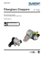
Operation
Fiberglass Choppers
GC-1021D
ENG
Fiberglass Roving Choppers
For use with Polyester Resin, and Gel-Coat
Maximum air pressure:
100 psi (0.7 MPa, 7 bar)
Important Safety Instructions
Read all warnings and instructions in
this manual. Save these instructions.
II 2 G
Contents
Warnings........................................................... 3
Important Safety Information.......................... 5
Grounding......................................................... 6
Set-Up................................................................ 7
Pressure Relief Procedure............................ 12
Start-Up........................................................... 13
Parts................................................................ 15
Assembly Drawings....................................... 16
Sub-Assembly Drawings............................... 20
Maintenance.................................................... 22
Accessories.................................................... 26
Technical Data................................................. 27
Graco Ohio Standard Warranty..................... 28
Graco Ohio Information................................. 28
2
GC-1021D
Warnings
The following warnings are for the setup, use, grounding, maintenance, and repair of this equipment.
The exclamation point symbol alerts you to a general warning and the hazard symbol refers to procedurespecific risk. Refer back to these warnings. Additional, product-specific warnings may be found throughout the
body of this manual where applicable.
• See Important Safety Information - MEKP, Polyester Resins and Gel-Coats and Spraying and Lamination
Operations section of this manual.
WARNING
FIRE AND EXPLOSION HAZARD
Changing Materials
Flammable fumes, such as solvent and paint fumes, in work area can ignite or explode. To help
prevent fire and explosion:
• Use equipment only in well ventilated area.
• Eliminate all ignition sources; such as pilot lights, cigarettes, portable electric lamps, and plastic
drop cloths (potential static arc).
• When changing
equipment
mul• Keepmaterials,
work area flush
free ofthe
debris,
including
solvent, rags and gasoline.
• to
Doensure
not plug
orthoroughly
unplug power
cords, or turn power or light switches on or off when flammable
tiple times
it is
clean.
fumes are present.
•
Ground
all equipment
in the
work
area. See Grounding instructions.
• Always clean
the fluid
inlet strainers
after
flushing.
• Use only grounded hoses.
• Hold
firmlymanufacturer
to side of grounded
pail when triggering into pail.
• Check with
your gun
material
for chemical
• If there is static sparking or you feel a shock, stop operation immediately. Do not use
compatibility.
equipment until you identify and correct the problem.
• Keep a working fire extinguisher in the work area.
Changing Materials
•
•
Most materials use ISO on the A side, but some use
ISO on the B side.
PERSONAL PROTECTIVE EQUIPMENT
You must wear appropriate protective equipment when operating, servicing, or when in the
Epoxies often have amines on the B (hardener)
operating area of the equipment to help protect you from serious injury, including eye injury,
side. Polyureas
often
havefumes,
amines
on the
(resin) loss. This equipment includes but is not limited to:
inhalation
of toxic
burns,
andBhearing
side. • Protective eyewear
• Clothing and respirator as recommended by the fluid and solvent manufacturer
• Gloves
• Hearing protection
SplatterMOVING
Hazard
PARTS HAZARD
This section Moving
is used parts
with some
RAM
which
could
getother
pushed
of the drums of sealant.
can pinch
orplates
amputate
fingers
and
bodyout
parts.
•
•
•
Keep clear of moving parts.
Do not operate equipment with protective guards or covers removed.
Pressurized equipment can start without warning. Before checking, moving, or servicing
equipment, follow the Pressure Relief Procedure in this manual. Disconnect power or air
supply.
WARNING
SPLATTER
HAZARD
TOXIC FLUID OR FUMES HAZARD
Hot
or toxic
can cause
serious
injury
if splashed
the eyesinorthe
oneyes
skin.orDuring
blow
off ofor
platen,
Toxic
fluids fluid
or fumes
can cause
serious
injury
or death ifinsplashed
on skin,
inhaled,
splatter
may occur.
swallowed.
Read
MSDS’s air
to know
the specific
hazards ofplaten
the fluids
are using.
• • Use
minimum
pressure
when removing
fromyou
drum.
•
•
Store hazardous fluid in approved containers, and dispose of it according to applicable
guidelines.
Always wear impervious gloves when spraying or cleaning equipment.
Burn Hazard
GC-1021D
For equipment used with heated material.
3
Skin Injection Hazard
Use with high pressure equipment, generally equipment with pressure rating of 900 psi or higher. There
sions of this section. 1) manual guns, 2) UL-1450 compliant equipment 3) automatic guns,/dispense val
tion valves, 4) heated hoses. Since the text contains mostly “Do not” statements, the symbols have lines
them.
Warnings
WARNING
WARNING
SKIN INJECTION
HAZARD
SKIN
INJECTION
HAZARD - Basic
High-pressure fluid from gun, hose leaks, or ruptured components will pierce skin. This may look
High-pressure fluid from gun, hose leaks, or ruptured components will pierce skin. This may l
like just a cut, but it is a serious injury that can result in amputation. Get immediate surgical
atreatment.
cut, but it is a serious injury that can result in amputation. Get immediate surgical treatm
Do
point
gun
at anyone
at of
any
•• Do
notnot
point
gun at
anyone
or at anyorpart
thepart
body.of the body.
Do
over
the spray
•• Do
notnot
put put
youryour
hand hand
over the
dispense
outlet.tip.
•• Do
notnot
stopstop
or deflect
leaks with
yourwith
hand,
body,
glove,body,
or rag.glove, or rag.
Do
or deflect
leaks
your
hand,
•• Engage
trigger
lock
when not
Do not
spray
without
tipspraying.
guard and trigger guard installed.
•• Follow
Pressure
Relief
Procedure
in spraying.
this manual, when you stop spraying and before cleaning,
Engage trigger lock when not
checking, or servicing equipment.
•
Follow Pressure Relief Procedure in this manual, when you stop spraying and before c
checking, or servicing equipment.
EQUIPMENT MISUSE HAZARD
SKIN
HAZARD
Use with UL1450 Compliance
MisuseINJECTION
can cause death
or serious -injury.
notnot
aim
the gun
at, or
spray
any or
person
or animal.
•DoDo
operate
the unit
when
fatigued
under the
influence of drugs or alcohol.
•• Do
not
exceed
the
maximum
working
pressure
or
temperature
rating of theFor
lowest
rated system
Keep hands and other body parts away from the discharge.
example,
do not try to sto
component.
See
Technical
Data
in
all
equipment
manuals.
any part of the body.
• Use fluids and solvents that are compatible with equipment wetted parts. See Technical Data
•
Always use the nozzle tip guard. Do not spray without nozzle tip guard in place.
in all equipment manuals. Read fluid and solvent manufacturer’s warnings. For complete
• information
Use Graco
nozzle
tips. request MSDS forms from distributor or retailer.
about
your material,
Use equipment
caution when
cleaning
and changing
nozzleparts
tips.immediately
in the case
the nozzle tip clo
•• Check
daily. Repair
or replace
worn or damaged
withwhere
genuine
manufacturer’s
replacement
parts only.Relief Procedure for turning off the unit and relieving the
spraying, follow
the Pressure
• Do
not alter
or modify equipment.
before
removing
the nozzle tip to clean.
•• Use
equipment
its intended
purpose.
Call your
distributor
for information.
Do not leaveonly
theforunit
energized
or under
pressure
while
unattended. When the unit is not
• Route hoses and cables away from traffic areas, sharp edges, moving parts, and hot surfaces.
off the unit and follow the Pressure Relief Procedure for turning off the unit.
• Do not kink or over bend hoses or use hoses to pull equipment.
•
High-pressure
spray is
able
to work
inject
toxins into the body and cause serious bodily injury.
• Keep
children and animals
away
from
area.
that injection
occurs,safety
get immediate
• Comply
with all applicable
regulations. surgical treatment.
•
•
•
•
•
4
Check hoses and parts for signs of damage. Replace any damaged hoses or parts.
This system is capable of producing XXXX psi. Use Graco replacement parts or accesso
rated a minimum of XXXX psi.
Always engage the trigger lock when not spraying. Verify the trigger lock is functioning pr
Verify that all connections are secure before operating the unit.
Know how to stop the unit and bleed pressure quickly. Be thoroughly familiar with the con
GC-1021D
Important Safety Information
Methyl Ethyl Ketone Peroxide (MEKP)
MEKP is among the more hazardous materials
found in commercial channels. Proper handling
of the “unstable (reactive)” chemicals presents a
definite challenge to the plastics industry. The
highly reactive property which makes MEKP
valuable to the plastics industry in producing the
curing reaction of polyester resins and gel-coats
also produces the hazards which require great care
and caution in its storage, transportation, handling,
processing and disposal.
Workers must be thoroughly informed of the hazards
that may result from improper handling of MEKP,
especially in regards to contamination and heat.
They must be thoroughly instructed regarding the
proper action to be taken in the storage, use and
disposal of MEKP and other hazardous materials
used in the laminating operation.
MEKP is flammable and potentially explosive,
as well as potentially damaging to the eyes and
skin.
Read material manufacturer’s warnings and
material MSDS to know specific hazards and
precautions related to MEKP.
Contaminated MEKP can become explosive.
Prevent contamination of MEKP with other materials, which includes, but is not limited to polyester
overspray, polymerization accelerators and promoters, and non-stainless metals. Even small amounts
of contaminates can make MEKP explosive. This reaction may start slowly, and gradually build-up heat,
which can accelerate until fire or an explosion result.
This process can take from seconds to days.
Heat applied to MEKP, or heat build-up from contamination reactions can cause it to reach what is
called its Self-Accelerating Decompisition Temperature (SADT), which can cause fire or explosion.
Spills should be promptly removed, so no residues
remain. Spillage can heat up to the point of selfignition. Dispose in accordance with manufacture’s
recommendation.
Store MEKP in a cool, dry and well-ventilated area
in the original containers away from direct sunlight
and away from other chemicals. It is strongly recommended that the storage temperature remain below
86° F (30° C). Heat will increase the potential for explosive decomposition. Refer to NFPA 432.
Keep MEKP away from heat, sparks and open
flames.
GC-1021D
Current catalysts are premixed and do not require
any diluents. GlasCraft strongly recommends that diluents not be used. Diluants add to the possibility of contaminates entering the catalyst system. Never dilute
MEKP with acetone or any solvent since this can produce an extremely shock-sensitive compound which
can explode.
Use only original equipment or equivalent parts
from GlasCraft in the catalyst system (i.e.: hoses, fittings, etc.)
because containing
a hazardous
chemical reaction
Spraying
materials
isocyanates
creates
may result between
partsand
and atomized
MEKP.
potentially
harmful substituted
mists, vapors,
particTo prevent contact with MEKP, appropriate personal
ulates.
protective equipment, including chemically impermeable gloves,
boots,
aprons and goggles
are required
Read
material
manufacturer’s
warnings
and material
for everyone
in the
work area.
MSDS
to know
specific
hazards and precautions
related to isocyanates.
Isocyanate Conditions
Polyester
Resins
and Gel-Coats
Prevent
inhalation
of isocyanate
mists, vapors, and
atomized particulates by providing sufficient ventilation in the work area. If sufficient ventilation is not
available, a supplied-air respirator is required for
everyone in the work area.
Spraying materials containing polyester resin and
gel-coats creates potentially harmful mist, vapors and
To prevent contact with isocyanates, appropriate peratomized particulates. Prevent inhalation by providing
sonal
protective
equipment,
including
chemically
sufficient
ventilation
and the use
of respirators
in the
impermeable
gloves,
boots,
aprons,
and
goggles, is
work area.
also
required
for everyone
in the warnings
work area.
Read
the material
manufacturer’s
and material MSDS to know specific hazards and precautions
related to polyester resins and gel-coats.
To prevent contact with polyester resins and gelcoats, appropriate personal protective equipment,
including chemically impermeable gloves, boots,
aprons and goggles are required for everyone in the
work area.
•
•
•
•
•
•
K
B
Material Self-ignition
To
we
an
Some materials may become self-igniting if applied
too thickly. Read material manufacturer’s warnings
Spraying
Lamination Operations
and
material and
MSDS.
Fo
B
Moisture Sensitivity of
Remove all accumulations of overspray, FRP sandIsocyanites
ings, etc. from the building as they occur. If this waste
Isocyanites
(ISO)
catalysts
in istwo
component
is allowed to
build are
up, spillage
of used
catalyst
more
likely
foam
and
polyurea
coatings.
ISO
will
react
with
moisture
to start a fire.
(such
as humidity)
to form
small, hard,
abrasive crystals,
If cleaning
solvents
are required,
read material
which
become warnings
suspended
the fluid.
Eventually
manufacture’s
andinmaterial
MSDS
to know a film
will
form on
the surface
and the ISO
will begin
to gel,
specific
hazards
and precautions.
(GlasCraft
recomincreasing
viscosity.
If used,
partially cured ISO
mends thatinclean-up
solvents
be this
nonflammable.)
will reduce performance and the life of all wetted parts.
The
amountrecommends
of film formation
and
rate of
crystalliGlasCraft
that you
consult
OSHA
zation
varies
depending
on
the
blend
of
ISO,
the
Sections 1910.94, 1910.106, 1910.107 and NFPA
humidity,
and the16,17,
temperature.
No. 33, Chapter
and NFPA No. 91 for further
guidance.
To prevent exposing ISO to moisture:
5
Som
abo
if ag
circ
Grounding
Some materials may become self-igniting if applied
too thickly. Read material manufacturer’s warnings
and material MSDS.
Moisture Sensitivity of
This equipment needs to be grounded.
Isocyanites
Ground the(ISO)
dispense
throughused
connection
a
Isocyanites
aregun
catalysts
in twoto
component
GlasCraft
approvedcoatings.
grounded ISO
fluid will
supply
hose.
foam
and polyurea
react
with moisture
(such as humidity) to form small, hard, abrasive crystals,
Check
your local
electrical code
and
related
manuals a film
which
become
suspended
in the
fluid.
Eventually
forform
detailed
grounding
instructions
of allwill
equipment
will
on the
surface
and the ISO
begin toingel,
the work area.
increasing
in viscosity. If used, this partially cured ISO
will reduce performance and the life of all wetted parts.
NOTICE
To prevent cross-contamination of the equipment’s
wetted parts, never interchange component A (isocyanate) and component B (resin) parts.
Foam Resins with 245 fa
Blowing Agents
Some foam blowing agents will froth at temperatures
above 90°F (33°C) when not under pressure, especially
if agitated. To reduce frothing, minimize preheating in a
circulation system.
The amount of film formation and rate of crystalliA grounding
and clamp
provided,
zation
varieswire
depending
onare
the
blend of ISO, the
assembly
p/n
17440-00
with
all
FRP
equipment.
humidity, and the temperature.
To prevent exposing ISO to moisture:
Rev. G 6/17/2008
6
21
GC-1021D
Some foam blowing agents will froth at temperatures
Moisture Sensitivity of
above 90°F (33°C) when not under pressure, especially
B
if agitated. To reduce frothing, minimize preheating in a
Isocyanites
Som
Moisture
Sensitivity of
circulation system.
Isocyanites (ISO) are catalysts used in two component
abo
Set-Up
foam and polyurea coatings. ISO will react with moisture
if ag
Isocyanites
(such as humidity) to form small, hard, abrasive crystals,
Isocyanites
(ISO) are
catalysts
used in glass
two component
Mounting
8. Adjust Chopper
mount
until chopped
enters spray
which
becomeInstructions
suspended in the fluid. Eventually a film
foam
and
polyurea
coatings.
ISO
will
react
with
moisture
pattern
at
desired
entry
location.
Chopped
glass
should
B-410,
LPA
2
Gun
will form on the surface and the ISO will begin to gel,
(such
as
humidity)
to
form
small,
hard,
abrasive
crystals,
be
uniformly
entering
the
spray
pattern
resulting
in
an
increasing in viscosity. If used, this partially cured ISO
which
become
suspended
in
the
fluid.
Eventually
a
film
evenly
distributed
resin
spray
and
chopped
glass
patwill reduce performance and the life of all wetted parts.
will form
surface
and the ISO will begin to gel,
ternon
on the
the test
substrate.
Theamount
followingofMounting
Instructions
The
film formation
and pertain
rate oftocrystalliincreasing in viscosity. If used, this partially cured ISO
mounting
a Model
B-410 onto
a Model
Model
zation
varies
depending
on the
blendLPA,
of ISO,
the
will reduce performance and the life of all wetted parts.
LPA-II Spray
humidity,
andGun.
the temperature.
The
film formation
ratepiece
of crystalliTestamount
sprayingof
should
be done onand
a clean
of paper
To prevent exposing ISO to moisture:
zation
varies and
depending
blend of ISO, the
or cardboard
disposedon
of the
properly.
humidity, and the temperature.
1. Remove Set Screw, P/N D-145-08C from the Gun
body located where the Chopper is mounted and reTo prevent exposing ISO to moisture:
place at the top of the handle. (see Fig. 1)
Rev. G 6/17/2008
21
2. Attach the Chopper assembly into the mounting
hold and tighten with the Chopper snout pointing
down into the resin spray pattern. The correct adjust-Rev. G 6/17/2008
ments for glass entering the pattern will be done
when the spray test is completed.
3. Chopper “On/Off” Lever, P/N B-310-11, located on
the base of the Chopper mount, should be in the
“OFF” position. (see Fig. 2)
4. Thread roving from box through the Roving Guidance
system and into the back of the Chopper Feed Bar,
P/N B-210-15. It is suggested that the top feed hole
be used if only one strand of glass is being used.
Mounting Instructions
B-410, & B-510, Indy Gun 23550-00
1. The B-410 / 510 Chopper Assy. Mounts to Cutter Pivot
Tube, P/N 21491-00 on Chopper Rotating Mount, P/N
23513-00. Tighten down Bar, P/N B-310-4 with Screws,
P/N 8212-16F. P/N, 17798-XX Hose attaches to fitting
P/N 1880-00 in back of gun.
5. After all components have been securely installed,
turn on main air supply slowly until fully on.
D-145-08C
Fig. 1
6. Activate the Chopper “On/Off” Lever to the “On” position. (see Fig. 2)
7. Depressing the Gun Trigger fully, a spray pattern of
resin and catalyst with chopped glass should now
be present.
GC-1021D
circ
7
Set-Up
2. The Slide Valve, P/N 20086-01 controls air to the
Gun for the Chopper. Sliding it forward turns the air
on, while sliding it back, turns the air off.
Chopper Air Requirements
100 PSI / 8 CFM
Adjusting Speed & Blower Air
1. The Blower Air is adjusted by the Thumb Screw, P/N B
210-32A2. Only a small amount of air is required to:
a.
Cool Chopper Head.
b.
Assist in Dispersing chop.
Speed Control / Muffler
1. The Muffler Assembly controls the Amount, and Speed
of air exhausting the Air Motor.
2. As the Speed Knob, P/N 21563-01 and Machine Screw,
P/N 21567-24F is turned out, the Air Motor speed increases.
3. Once it is set, Lock the Knob / Screw down with the
3. The Gun Trigger is staged: ¼ pull on the trigger will
actuate material only. Full back on the trigger actutes the Chopper and Material. The Stager can be
adjusted by adjusting the Set screw, P/N 23532-01
in the Gun Trigger, p/n 23503-00.
Body, P/N 21561-00.
Adjusting Chopper Mount
1. Loosen Screw, P/N 8212-16F to twist the Chopper side
to side on the Pivot Tube, P/N 21491-00. Retighten once
it is set.
Loosen screws
2. Loosen Screw, P/N 20188-16C to pivot the Chopper up
& down on the Chopper Bracket, P/N 23512-00. Retighten once it is set.
Loosen
8
GC-1021D
atomized
by providing sufficient
Toparticulates
prevent cross-contamination
of theventilaequipment’s
foam and polyurea coatings. ISO will react with moisture
tion in the
workparts,
area. never
If sufficient
ventilation
is not A (isocy•
wetted
interchange
component
(such as humidity) to form small, hard, abrasive crystals,
available,
a supplied-air
respirator
is required
anate)
and component
B (resin)
parts.for
which
suspended
in the
fluid. Eventually
a film
Somebecome
materials
may become
self-igniting
if applied
everyone in the work area.
will
form
on
the
surface
and
the
ISO
will
begin
to
gel,
too thickly. Read material manufacturer’s warnings
•
increasing
in viscosity.
and material
MSDS. If used, this partially cured ISOTo prevent contact with isocyanates, appropriate perwill reduce performance and the life of all wetted parts.
sonal
equipment,
including
chemically
2. Air protective
Hose P/N 17798-XX
attaches
to fitting,
P/N
impermeable
gloves,
boots,
aprons,
and
goggles, is
The
amount of film formation and rate of crystalli- 1880-00 on back of gun.
For B-510
for everyone
in the work
area.at temperatures
zation
depending
on the
blend
of ISO, the also required
Loosenvaries
Lock Nut,
P/N 7729-04,
Pivot
Chopper
Some foam
blowing agents
will froth
humidity,
and
the
temperature.
Mount to desired angle, Retighten P/N 7729-04.
above 90°F (33°C) when not under pressure, especially
Once
general
position
can
be
found,
fine
tuning
can
if agitated. To reduce frothing, minimize preheating in a
To prevent exposing ISO to moisture:
be adjusted by moving the chute, P/N B-510-22.
circulation system.
Isocyanites (ISO) are catalysts used in two component
foam and polyurea coatings. ISO will react with moisture
3. The
Snout, P/Nto
23543-00
is standard
with the Indy
(such
as humidity)
form small,
hard, abrasive
crystals,
To
System.
The
end
of
the
Snout
is
adjustable.
Optional
which become suspended in the fluid. Eventually
a film
w
snouts
thethe
B-410
Rev.form
G 6/17/2008
21
will
onare
theavailable
surfacefor
and
ISOonly,
will which
begininclude
to gel,
an
the B-210-91 and B-210-92.
increasing in viscosity. If used, this partially cured ISOSome materials may become self-igniting if applied
will reduce performance and the life of all wetted parts.too thickly. Read material manufacturer’s warnings
and material MSDS.
The
film formation
ratepiece
of crystalliTest amount
spraying of
should
be done onand
a clean
of
zation
depending
on the blend
of ISO, the
paper varies
or cardboard
and disposed
of properly.
humidity, and the temperature.
So
To prevent exposing ISO to moisture:
ab
Mounting Instructions
if a
B-410, B-510, Indy-X Gun 23575-00
circ
Isocyanites (ISO) are catalysts used in two component
foam and polyurea coatings. ISO will react with moisture
3. The Cutter Valve Lever, P/N B-310-11 controls air
(such as humidity) to form small, hard, abrasive crystals,
Rev.
G
6/17/2008
21
1. The B-410 / B-510 Chopper Assembly mounts to
flow to the chopper. Perpendicular to the
which
become
suspended
in
the
fluid.
Eventually
a
film
Cutter Pivot Tube, P/N 21491-00 on Chopper Valve,
Chopper Valve = Air On.
on the surface and the ISO will begin to gel,
P/N 23569-00. Once Chopper is set, tighten Cutter will form
Inline with Valve = Air OFF.
increasing
in viscosity. If used, this partially cured ISO
Clip, P/N B-310-4 with Screws.
will reduce performance and the life of all wetted parts.
Set-Up
Moisture Sensitivity of
Isocyanites
Foam Resins with 245 fa
Blowing Agents
Material Self-ignition
F
B
Moisture Sensitivity of
Isocyanites
The
of film
formation
rate
crystalliThis amount
is a positive
ON/OFF
valve. and
It does
notofregulate
zation
varies depending on the blend of ISO, the
Air Flow.
humidity, and the temperature.
To prevent exposing ISO to moisture:
Rev. G 6/17/2008
GC-1021D
K
B
9
Isocyanites (ISO) are catalysts used in two component
foam and polyurea coatings. ISO will react with moisture
(such as humidity) to form small, hard, abrasive crystals,
which become suspended in the fluid. Eventually a film
will form on the surface and the ISO will begin to gel,
increasing in viscosity. If used, this partially cured ISO
4. The Catalyst Atomizing Air Line connects to Connec- will reduce performance and the life of all wetted parts.
tor Fitting, P/N 20796-00. When the gun is triggered,
The
amount of film formation and rate of crystalliFor B-510
Line Air will run the Chopper Motor and regulated air
zation
varies
depending
on theFine
blend
of ISO,
A general
position
can be found.
tuning
of thethe
will flow thru to the atomized circuit.
humidity,
and
the
temperature.
Glass angle can be adjusted by moving the Chute
Set-Up
P/N, B-510-22.
To prevent
exposing ISO to moisture:
Centering Adjust
Loosen Bar Screws, P/N 8212-16F and Twist Chopper
Rev.
G right
6/17/2008
left or
to desired location, then retighten P/N 8212-
16F Shoulder Screw.
Bar
Chopper Air Requirements
100 PSI @ 8 CFM
Adjusting Speed & Blower Air
1. The blower air is adjusted by the Thumb Screw, P/N
B-210-32A2. a small amount of air is required to:
Mounting Instructions
B-410, B-510, Formula Gun 23750-00
1. The B-410 / B-510 Chopper Assembly mounts to
Cutter Pivot Tube, P/N 21491-00. Once the Chopper
is set, tighten Cutter Clip, P/N B-310-4 with Screws.
a. Cool Chopper Head
b. Assist in Dispersing chop.
Adjusting Chopper Mount
Angle Adjust:
1. Loosen Lock Nut, P/N 7729-04, Pivot Chopper
Mount to desired Angle. Retighten, P/N 7729-04 Hex
Nut.
Lock Nut
10
GC-1021D
Read material manufacturer’s warnings and material
MSDS to know specific hazards and precautions
related to isocyanates.
ISO, such as those supplied with your system.
•
Never use reclaimed solvents, which may contain
moisture. Always keep solvent containers closed
when not in use.
•
Never use solvent on one side if it has been contam-
Prevent inhalation of isocyanate mists, vapors, and
Set-Up
atomized particulates by providing sufficient ventilation in the work area. If sufficient ventilation is not
2. Air Hose P/N 17798-XX attaches to fitting, P/N
available, a supplied-air respirator is required for
1880-00 on back of gun.
everyone in the work area.
Chopperinated
Air Requirements
from the other side.
100 PSI / 8 CFM
•
Always lubricate threaded parts with ISO pump oil
To prevent contact with isocyanates, appropriate peror grease when reassembling.
Adjusting Speed & Blower Air
sonal protective equipment, including chemically
impermeable gloves, boots, aprons, and goggles, is
1. The Blower Air is adjusted by the Thumb Screw, P/N Balso required for everyone in the work area.
210-32A2. Only a small amount of air is required to:
a.
Cool Chopper Head.
b.
Assist in Dispersing chop.
Material Self-ignition
Keep Components A and
B Separate
NOTICE
Speed
/ Muffler
ToControl
prevent cross-contamination
of the equipment’s
wetted parts, never interchange component A (isocy-
Some materials may become self-igniting if applied
too thickly. Read material manufacturer’s warnings
and material MSDS.
Moisture Sensitivity of
Isocyanites
component
(resin)
parts.
1. The anate)
Muffler and
Assembly
controlsBthe
Amount,
and Speed
of air exhausting the Air Motor.
Foam Resins with 245 fa
P/N 21567-24F is turned out, the Air Motor speed inBlowing Agents
creases.
2. As the Speed Knob, P/N 21563-01 and Machine Screw,
Some foam blowing agents will froth at temperatures
above
(33°C)
when/ Screw
not under
3. Once
it is 90°F
set, Lock
the Knob
downpressure,
with the especially
if agitated.
To reduce frothing, minimize preheating in a
Body,
P/N 21561-00.
circulation system.
Isocyanites (ISO) are catalysts used in two component
foam and polyurea coatings. ISO will react with moistureAdjusting Chopper Mount
(such as humidity) to form small, hard, abrasive crystals,
which become suspended in the fluid. Eventually a film 1. Loosen Screw, P/N 8212-16F to twist the Chopper side
3. The Cutter Valve, P/N 23776-00 controls the air
to side on the Pivot Tube, P/N 21491-00. Retighten once
will form on the surface and the ISO will begin to gel,
flow to the chopper.
it is set.
increasing in viscosity. If used, this partially cured ISO
will reduce performance and the life of all wetted parts.
The
of film
formation
ratenot
ofregulate
crystalliThisamount
is a positive
ON/OFF
valve.and
It does
zation
varies depending on the blend of ISO, the
Air Flow.
humidity, and the temperature.
To prevent exposing ISO to moisture:
Rev. G 6/17/2008
21
2. Loosen Screw, P/N 7958-16C to pivot the Chopper up
& down on the Chopper Bracket, P/N 23512-00. Retighten once it is set.
GC-1021D
11
Pressure Relief Procedure
To relieve fluid and air pressures:
1. Push down Yellow slide valve, P/N 21402-00 to bleed
off air to system.
2. Open P/N 21228-00 on catalyst pump to recirculation
position.
3. Open P/N 21192-00 on bottom of material pump.
12
GC-1021D
Start-Up
Air Requirements
All GlasCraft Choppers require 8 CFM (cubic feet per
minute) @ 100 PSI. of dry, filtered, compressed air. The
air supply hose to the Chopper must be new and have
at least a 5/16” inside diameter.
Notice
Do not attempt to use lower air pressures or a smaller
hose as erratic operation may result.
Notice
Do not wet the roving or attempt to feed
frayed roving into the Chopper as this may cause it to
wrap around the feed roller and jam.
2. The Motor Oiler is located on the forward port of the Air
Motor. It is recommended that the Oiler Felt, P/N 378,
be lubricated with Air Motor Oil, P/N 562. Depending on
use, it is generally recommended that two or three drops
of oil be placed on the Felt every other day.
Chopper Operation
Models B-410 / B-510
1. To introduce roving to the Chopper, cut the free end
of the roving cleanly and double it over approximately one inch from the end. Feed into one of the
three holes provided in the back of the cutter while
running at moderate speed.
B-410
B-410
B-510
GC-1021D
B-510
13
Start-Up
3. The Muffler/Speed Control is located on the rear
port of the Air Motor. Adjustment of Knob, P/N
21563-01 controls the Air Motor speed and determines the cutting rate. Adjust this valve until the desired glass content is achieved.
Some materials may become self-igniting if applied
too thickly. Read material manufacturer’s warnings
and material MSDS.
Moisture Sensitivity of
Isocyanites
Isocyanites (ISO) are catalysts used in two component
foam and polyurea coatings. ISO will react with moisture
(such as humidity) to form small, hard, abrasive crystals,
which become suspended in the fluid. Eventually a film
will form on the surface and the ISO will begin to gel,
increasing in viscosity. If used, this partially cured ISO
B-510
will reduce performance and the life of all wetted parts.
B-410
The amount of film formation and rate of crystalliThis Valve
should
be at least
openof
at ISO,
all times
zation
varies
depending
onslightly
the blend
the
or the Chopper
maytemperature.
tend to fill and jam.
humidity,
and the
To prevent exposing ISO to moisture:
5. Adjust this valve until a good glass/resin fan results with a
minimum of drop-off. If an excessive amount of bypass air is
used, the roving may filamentize or cotton, causing various
wet-out problems.
Rev. G 6/17/2008
6. When desired adjustment has been made, lock Thumb
Screw, P/N B-210-32A2, in place by tightening Lock Nut,
P/N B-210-32A1. Do not over-tighten!
Roving Cut-Length Adjustment
B-510
4. The Chopper Blower Control Valve is located on
the rear of the Back Plate. Adjustment of Thumb
Screw, P/N B-210-32A2 controls the amount of bypass air which serves to vary the dispersion of the
cut roving as it leaves the Chopper.
The cut length of the roving fibers may vary from 1/2” to 4”
depending upon the number of blades in the cutting head.
The cutting head has a circumference of 4” and is divided by
eight slots at 1/2” intervals. Any number of blades may be
omitted to achieve cut-lengths greater than 1/2” or blends of
lengths. The most popular length in use today is 1”, which
may be achieved with four equally spaced blades. The
chopper is delivered to you set in this matter.
Mask FilterEar
Relieve all air pressure from the system before attempting
any repair or maintenance procedures on this equipment.
Do not operate the Chopper with the cover or guard removed.
The blades may fly free if improperly installed.
B-410
14
GC-1021D
T
w
a
F
B
So
ab
if a
cir
Parts
Fiberglass Roving Choppers B-410 & B-510
Standard Equipment
Part
Number
Description
B-410
Fiberglass Chopper
GC-1021
USER MANUAL
Standard Equipment
Part
Number
Description
B-510
Fiberglass Chopper
GC-1021
USER MANUAL
GC-1021D
15
Assembly Drawings
124377
16
124377
124377
B-410-13
B-310-24-2
B-410 Chopper
REVISION R
GC-1021D
Assembly Drawings
B-410 Chopper
Part
Number
Description
378
FELT OILER
13076-10
O-RING
13076-11
O-RING
17390-02
SPRING WASHER
5133-62MD
SNAP RING
7606-05
O-RING
7733-13
NUT
7734-06
LOCK WASHER
7958-48C
MACHINE SCREW
8160-12C
SET SCREW
8212-16F
MACHINE SCREW
Part
Number
Description
Qty.
9944-16C
MACHINE SCREW
21561-00
LOCK NUT
1
21568-00
MUFFLER ASSEMBLY
21562-00
FELT WASHER
2
AM-100-1
AIR MOTOR ASSEMBLY
21563-01
SPEED KNOB
1
B-210-10A
AIR MOTOR SPACER
21564-00
MUFFLER TUBE
1
B-210-14A
NUT GUARD
21567-24F
SCREW
1
B-210-14B
SNAP RING
7486-23
WASHER
1
B-210-14C
GUARD LINER
B-210-14E
CHOPPER GUARD
B-210-15-1
FEED BAR
B-210-15-2
BUSHING
B-210-16A
CUTTING BLADE BAR
B-210-16B
RET.BAR SPRING
B-210-16C
CUTTER HEAD
B-210-16E
CUTTING HEAD BOLT
B-210-16F
SNAP RING
B-210-17
CUTTING HEAD BLADE
B-210-32A2
THUMB SCREW
B-210-32B
CONTROL BLOCK NUT
B-210-71
CHOPPER PARTS KIT
B-210-91
CUTTER GUARD SNOUT
B-310-24-2
ECCENTRIC NUT
B-310-30
CHOPPER BLOWER TUBE
B-310-4
Description
Qty.
B-210-17
CUTTING HEAD BLADE
100
B-210-21W
SMALL WHITE RUBBER WHEEL
1
5133-62MD
SNAP RING
2
CUTTER CLIP
B-410-01
AIR MOTOR TUBE
B-410-02-3
NUT CAP
B-410-07
TEE SWAGE PIPE FITTING
B-410-13
CUTTER BACK PLATE
GC-1021
USER MANUAL
GC-1021D
Part
Number
REVISION R
17
Assembly Drawings
B-510 Chopper
REVISION D
18
GC-1021D
Assembly Drawings
B-510 Chopper
Part
Number
Description
Part
Number
Description
378
FELT OILER
B-510-17
COMPRESSION SPRING
13076-10
O-RING
B-510-18
COMPRESSION SPRING
13076-11
O-RING
B-510-19
RETAINING RING
16828-01
RETAINING RING
B-510-20
GUARD CASTING
17390-01
SPRING WASHER
B-510-21
TURN KNOB
7486-03
WASHER
B-510-22
CHOPPER CHUTE
7606-05
O-RING
B-510-23
SCREW
7734-06
LOCK WASHER
B-510-24
COVER INSERT
8160-08C
SET SCREW
B-510-25
1 in. CUTTING HEAD BLADE
8160-12C
SET SCREW
B-510-71
CUTTER SPARE PARTS KIT
8212-12F
SCREW
GC-1021
USER MANUAL
8212-16F
SCREW
9944-12C
SCREW
9944-16C
SCREW
9944-36C
SCREW
21568-00
CHOPPER MUFFLER ASSEMBLY
23531-02
SHOULDER SCREW
23535-01
SNAP RING
Part
Number
Description
Qty.
21561-00
LOCK NUT
1
21562-00
FELT WASHER
2
21563-01
SPEED KNOB
1
21564-00
MUFFLER TUBE
1
AM-100-2
AIR MOTOR ASSEMBLY
B-210-10A
AIR MOTOR SPACER
B-210-16F
SNAP RING
21567-24F
SCREW
1
B-210-17
CUTTING HEAD BLADE
7486-23
WASHER
1
B-210-32A1
LOCK NUT
B-210-32A2
THUMB SCREW
B-210-32B
CONTROL BLOCK NUT
B-310-4
CUTTER CLIP
B-410-01
AIR MOTOR TUBE
B-410-02-3
NUT CAP
B-410-07
TEE SWAGE PIPE FITTING
B-510-01
BACK PLATE
B-510-02
SLIDING LOCK
B-510-03
ADJUSTMENT KNOB
B-510-04
ADJUSTMENT WASHER
B-510-05
FEED BAR
B-510-08
LARGE WHITE RUBBER WHEEL
B-510-09
ROLLER HUB
B-510-11
IDLER BEARING
B-510-14
ANGLE WEDGE CUTTER HEAD
B-510-15
ANGLE WEDGE INSERT
B-510-16
BLOWER TUB
GC-1021D
REVISION D
19
Sub-Assembly Drawings
AM-100 Air Motor (Used with B-410 Chopper)
AM-109
AM-109
Gasket
Gasket
AM-114
AM-115
Rear Cap
Front Cap
5133-62MD
AM-113
Snap Ring
Seal
N/A
N/A
AM-112
Bearing
B-210-23
Tire Shaft
NOTE:
End Cap
(Not Shown)
N/A
B-210-23A
Roll Pin
AM-110
AM-103
Rotor Vane
R oll Pin
REVISED 2/98
REPAIR KIT: AM-120
20
GC-1021D
Sub-Assembly Drawings
AM-100-2 Air Motor (Used with the B-510 Chopper)
AM-109
AM-109
Gasket
G asket
AM-114
AM-115
Rear Cap
Front Cap
AM-113
Seal
N/A
N/A
AM-112
Bearing
NOTE:
End Cap
(Not Shown)
N/A
AM-110
AM-103
R oll Pin
Rotor Vane
REPAIR KIT: AM-120
GC-1021D
21
Isocyanites
if agitated. To reduce frothing, minimize preheating in ifa a
Isocyanites
circulation system.
Isocyanites (ISO) are catalysts used in two component
Isocyanites (ISO) are catalysts used in two component
foam and polyurea coatings. ISO will react with moisture
foam and polyurea coatings. ISO will react with moisture
(such as humidity) to form small, hard, abrasive crystals,
(such as humidity) to form small, hard, abrasive crystals,
which become suspended in the fluid. Eventually a film
which become suspended in the fluid. Eventually a film
will form on the surface and the ISO will begin to gel, will form on the surface and the ISO will begin to gel,
Blade Replacement
2. To re-insert Blades, place in slot, sharp edge out.
increasing in viscosity. If used, this partially cured ISOincreasing in viscosity. If used, this partially cured ISO
will reduce performance and the life of all wetted parts.
will reduce performance and the life of all wetted parts.
cir
Maintenance
The amount of film formation and rate of crystalliRefer to
Figuredepending
7 illustrationonduring
the following
zation
varies
the blend
of ISO, the
Blade
Replacement
instructions.
humidity, and the temperature.
To prevent exposing ISO to moisture:
Mask FilterEar
UseGextreme
caution when replacing cutter blades to
Rev.
6/17/2008
avoid severe injury or amputation.
B-410
1. Using a small slotted-blade screwdriver, carefully pry
out the Blade Retainer Bar, P/N B-210-16A, Retainer
Bar Spring, P/N B-210-16B and the Blade, P/N
B-210-17. Be careful not to lose these small parts
as they come free of the slot. Clean slots before replacing Blades.
The amount of film formation and rate of crystalliIt is very
important
that the on
Blade
held of
against
zation
varies
depending
thebe
blend
ISO, the
the
side
of
the
slot
which
will
contact
the
Anvil
Roller
first.
humidity, and the temperature.
To prevent exposing ISO to moisture:
3. Next, place in the Blade Retainer Bar, P/N B-210-16A
and install Spring, P/N B-210-16B with a screwdriver or
needle-nose pliers.
Rev. G 6/17/2008
B-510
1. Using a 1/8” Allen Wrench, loosen and remove P/N,
B-510-23 screw. This will allow removal of P/N, B-51015 wedge insert.
2. Remove old blade.
3. Clean slot on P/N, B-510-14 as necessary.
4. Install new blade. Set insert in properly.
5. Reinstall P/N, B-510-23 screw and snug tightly.
22
GC-1021D
21
Maintenance
CORRECT
BLADE ASSEM BLY
LARGE RECTANGULAR
NOTCH VISIBLE
BLADE
CUTTER
HEAD
BLADE RETAINER BAR
THIS MUST BE VISIBLE
WHEN GUARD ASSEMBLY
IS REMOVED.
CUTTER
HEAD
RETAINER BAR SPRING
INCORRECT
BLADE ASSEM BLY
INSTALL BLADE FROM
THIS POSITION ONLY!
BLADE
BLADE RETAINER BAR
RETAINER BAR SPRING
SMALL NOTCH
THIS SIDE OF ASSEM BLY
MUST FACE CUTTER PLATE
CUTTER
HEAD
CUTTER
HEAD
B-210-16A
BLADE RETAINER
BAR
B-210-16B
RETAINER BAR
SPRING
B-210-17
BLADE
CORRECT
BLADE ASSEM BLY
Fig. 7
GC-1021D
23
Maintenance
Anvil Sleeve Replacement
If the Chopper fails to cut properly with new blades, the
anvil roller needs replaced.
1. Remove Retaining Ring, P/N 5133-62MD with a
screwdriver. Care must be taken not to spring the
Retaining Ring excessively.
2. Slide or pry off the old anvil roller and install a replacement by pressing it in place. To prevent the
blades from making deep cuts in roller’ surface,
be sure to rotate the roller as it is pressed on.
Notice
Do not use a hammer when installing a new sleeve as
permanent damage may result.
3. Replace the Retaining ring with ordinary pliers.
4. Operate the Chopper for a minute or so with the
cover in place, to run the new anvil roller. The Chopper should now start and run freely.
Chopper Adjustments
Should adjustments be necessary, they may be accomplished by simply loosening either the Cutting Head or
the Idler Bearing, rotating the Eccentric Nut in the back
and retightening.
B-510 Adjustments
The B-510 adjustments are set at the factory during final inspection of the unit. This adjustment is set without running
glass roving through the chopper. It is also important to remember that the chopper head is the drive mechanism of
the assembly, adjustments are being made to the Rubber
Roller, P/N B-510-08 and Idler Bearing, P/N B-510-11.
After feeding in the strands of roving “In Process” adjustments may be required. This adjustment is dependent on the
type of glass roving being used and the number of strands.
Adjust as follows:
1. Shut off air supply to chopper.
2. Loosen Lock Screw, P/N 9944-16C for the Rubber Roller, P/N B-510-08.
3. Loosen Adjustment Knob, P/N B-510-03 for the P/N
B-510-08. This action will allow the glass in between
the Cutter Head and Roller to relax and move roller
away from Cutter Head slightly.
4. Retighten Lock Screw, P/N 9944-16C.
5. Loosen Lock Screw, P/N 9944-16C for the Idler Bearing,
P/N B-510-11.
6. The Idler Bearing should now find its setting with the
spring pressure applied to it.
B-410 Adjustments
7. Retighten Lock Screw, P/N 9944-16C.
1. Cutting head should have sufficient squeeze to cut
properly. Excessive Anvil Squeeze or roll interference will overload the motor or create starting problems. Insufficient Squeeze will result in incomplete
cutting.
2. Idler Bearing should be adjusted so there is only
slight contact with the Anvil Roller. Excessive pressure will create motor drag and cause starting problems. Insufficient squeeze will allow the roving not
to feed or drop out of the chopper when it is stopped.
24
8. Turn air supply on to chopper and operate, verify glass
is consistently cut to length. Chopper Air Motor
Notice
The clearances in this Motor range are from 0.0015 to
0.002 and are extremely critical. For this reason, it is
advisable that the Motor NEVER be disassembled in the
shop!
GC-1021D
Maintenance
Model B-410 / B-510
The Air Motor on your Chopper is precision built and
under normal operation will last hundreds of hours of
continuous use with proper care. It is recommended that
the Oiler Felt, P/N 378, be lubricated with Air Motor Oil,
P/N 562. Depending on use, it is generally recommended that two or three drops of oil be placed on the Felt
every other day.
Before cutting glass:
1) RELIEVE AIR PRESSURE TO CHOPPER.
2) Remove Chopper Guard and carefully wipe clean
excess oil on Guard, Anvil Sleeve, etc.
3) Replace Guard.
GC-1021D
25
Accessories
B-510-71 Repair Kit
Part
Number
Description
Qty.
B-510-25
BLADES
100
B-510-08
LARGE WHITE RUBBER WHEEL
1
B-210-71 Repair Kit
Part
Number
Description
Qty.
B-210-17
BLADES
100
B-210-21W
SMALL WHITE RUBBER WHEEL
1
5133-62MD
SNAP RING
2
AM-120 Repair Kit
Part
Number
Description
Qty.
AM-103
VANE
8
AM-109
GASKET
2
AM-112
BEARING
2
AM-113
SEAL
1
7606-17
O-RING
1
Chopper Snout Options
Part
Number
26
Description
Gun
23543-00
OPEN SNOUT
INDY / FORMULA
23543-01
CLOSED SNOUT
INDY / FORMULA
23543-02
OPEN SNOUT
INDY X
B-210-91
CLOSED SNOUT (NARROW)
LPA2 / INDY / FORMULA
B-210-92
CLOSED SNOUT (WIDE)
LPA2 / INDY / FORMULA
GC-1021D
Technical Data
GC-1021D
Category
Data
Maximum Air Inlet Pressure
100 psi (0.7 MPa, 7 bar)
Maximum Fluid temperature
100° F (38° C)
Dimensions B-410
6.93 L X 5.32 W X 3.84 H (176.02 X 135.13 X 97.54 mm)
Dimensions B-510
6.90 L X 5.52 W X 5.67 H (175.26 X 140.21 X 144.02 mm)
Weight B-410
2.75 Lbs.
Weight B-510
3.05 Lbs.
Sound Pressure B-410
65.03 dB(A)
Sound Pressure B-510
91.35 dB(A)
Sound Power, measured per ISO 9614-2 B-410
85.4 dB(A)
Sound Power, measured per ISO 9614-2 B-510
86.84 dB(A)
27
Graco Ohio Standard Warranty
Graco warrants all equipment referenced in this document which is manufactured by Graco and bearing its name to be free from defects in
material and workmanship on the date of sale to the original purchaser for use. With the exception of any special, extended, or limited warranty
published by Graco, Graco will, for a period of twelve months from the date of sale, repair or replace any part of the equipment determined by
Graco to be defective. This warranty applies only when the equipment is installed, operated and maintained in accordance with Graco’s written
recommendations.
This warranty does not cover, and Graco shall not be liable for general wear and tear, or any malfunction, damage or wear caused by faulty installation, misapplication, abrasion, corrosion, inadequate or improper maintenance, negligence, accident, tampering, or substitution of non-Graco
component parts. Nor shall Graco be liable for malfunction, damage or wear caused by the incompatibility of Graco equipment with structures,
accessories, equipment or materials not supplied by Graco, or the improper design, manufacture, installation, operation or maintenance of
structures, accessories, equipment or materials not supplied by Graco.
This warranty is conditioned upon the prepaid return of the equipment claimed to be defective to an authorized Graco distributor for verification of
the claimed defect. If the claimed defect is verified, Graco will repair or replace free of charge any defective parts. The equipment will be returned
to the original purchaser transportation prepaid. If inspection of the equipment does not disclose any defect in material or workmanship, repairs
will be made at a reasonable charge, which charges may include the costs of parts, labor, and transportation.
THIS WARRANTY IS EXCLUSIVE, AND IS IN LIEU OF ANY OTHER WARRANTIES, EXPRESS OR IMPLIED, INCLUDING BUT NOT LIMITED TO WARRANTY OF MERCHANTABILITY OR WARRANTY OF FITNESS FOR A PARTICULAR PURPOSE.
Graco’s sole obligation and buyer’s sole remedy for any breach of warranty shall be as set forth above. The buyer agrees that no other remedy
(including, but not limited to, incidental or consequential damages for lost profits, lost sales, injury to person or property, or any other incidental
or consequential loss) shall be available. Any action for breach of warranty must be brought within two (2) years of the date of sale.
GRACO MAKES NO WARRANTY, AND DISCLAIMS ALL IMPLIED WARRANTIES OF MERCHANTABILITY AND FITNESS FOR A PARTICULAR PURPOSE, IN CONNECTION WITH ACCESSORIES, EQUIPMENT, MATERIALS OR COMPONENTS SOLD BUT NOT MANUFACTURED BY GRACO. These items sold, but not manufactured by Graco (such as electric motors, switches, hose, etc.), are subject to the warranty,
if any, of their manufacturer. Graco will provide purchaser with reasonable assistance in making any claim for breach of these warranties.
In no event will Graco be liable for indirect, incidental, special or consequential damages resulting from Graco supplying equipment hereunder,
or the furnishing, performance, or use of any products or other goods sold hereto, whether due to a breach of contract, breach of warranty, the
negligence of Graco, or otherwise.
FOR GRACO CANADA CUSTOMERS
The Parties acknowledge that they have required that the present document, as well as all documents, notices and legal proceedings entered
into, given or instituted pursuant hereto or relating directly or indirectly hereto, be drawn up in English. Les parties reconnaissent avoir convenu
que la rédaction du présente document sera en Anglais, ainsi que tous documents, avis et procédures judiciaires exécutés, donnés ou intentés,
à la suite de ou en rapport, directement ou indirectement, avec les procédures concernées.
Graco Ohio Information
For the latest information about Graco products, visit www.graco.com
TO PLACE AN ORDER, contact your Graco distributor or call to identify the nearest distributor.
Toll Free: 1-800-746-1334 or Fax: 330-966-3006
All written and visual data contained in this document reflects the latest product information available at the time of publication.
Graco reserves the right to make changes at any time without notice.
Original instructions. This manual contains English. MM GC-1021
Graco Headquarters: Minneapolis
International Offices: Belgium, China, Japan, Korea
GRACO OHIO INC. 8400 PORT JACKSON AVE NW, NORTH CANTON, OH 44720
Copyright 2008, Graco Ohio Inc. is registered to ISO 9001
www.graco.com
Revised 01/2011