1
VisionWare
Reference Guide
Version 3.0
Part Number 00713-00200, Rev. A
September 1996
150 Rose Orchard Way • San Jose, CA 95134 • USA • Phone (408) 432-0888 • Fax (408) 432-8707
Otto-Hahn-Strasse 23 • 44227 Dortmund • Germany • Phone 0231/75 89 40 • Fax 0231/75 89 450
11, Voie la Cardon • 91126 • Palaiseau • France • Phone (1) 69.19.16.16 • Fax (1) 69.32.04.62
1-2, Aza Nakahara Mitsuya-Cho • Toyohashi, Aichi-Ken • 441-31 • Japan • (0532) 65-2391 • Fax (0532) 65-2390
The information contained herein is the property of Adept Technology, Inc., and shall not
be reproduced in whole or in part without prior written approval of Adept Technology,
Inc. The information herein is subject to change without notice and should not be construed as a commitment by Adept Technology, Inc. This manual is periodically reviewed
and revised.
Adept Technology, Inc., assumes no responsibility for any errors or omissions in this document. Critical evaluation of this manual by the user is welcomed. Your comments assist
us in preparation of future documentation. A form is provided at the back of the book for
submitting your comments.
Copyright 1992, 1996 by Adept Technology, Inc. All rights reserved.
The Adept logo is a registered trademark of Adept Technology, Inc.
Adept, AdeptOne, AdeptOne-MV, AdeptThree, AdeptThree-MV, PackOne, PackOne-MV,
HyperDrive, Adept 550, Adept 550 CleanRoom, Adept 1850, Adept 1850XP,
A-Series, S-Series, Adept MC, Adept CC, Adept IC, Adept OC, Adept MV,
AdeptVision, AIM, VisionWare, AdeptMotion, MotionWare, PalletWare,
AdeptNet, AdeptFTP, AdeptNFS, AdeptTCP/IP, AdeptForce, AdeptModules,
and V+ are trademarks of Adept Technology, Inc.
Any trademarks from other companies used in this publication
are the property of those respective companies.
Printed in the United States of America
Table of Contents
Chapter 1.
1.1
1.2
1.3
Chapter 2.
2.1
2.2
2.3
2.4
2.5
2.6
Chapter 3.
3.1
3.2
3.3
3.4
3.5
3.6
3.7
3.8
3.9
Introduction and Overview . . . . . . . . . . . . . . . . . . . . . . . . . . . . . . . . . . . . . . . . . . . . . . . . . . . . . . . . . . 1
Do You Really Need to Read This Manual? . . . . . . . . . . . . . . . . . . . . . . . . . . . . . . . . . . . . . . .
Prerequisite Background Information . . . . . . . . . . . . . . . . . . . . . . . . . . . . . . . . . . . . . . . . . . . . . . .
Overview of the Aim Vision Module . . . . . . . . . . . . . . . . . . . . . . . . . . . . . . . . . . . . . . . . . . . . . . . .
Vision Database . . . . . . . . . . . . . . . . . . . . . . . . . . . . . . . . . . . . . . . . . . . . . . . . . . . . . . . . . . . . . . . . . . . . . . .
Menu Summary . . . . . . . . . . . . . . . . . . . . . . . . . . . . . . . . . . . . . . . . . . . . . . . . . . . . . . . . . . . . . . . . . . . . . . .
Routines . . . . . . . . . . . . . . . . . . . . . . . . . . . . . . . . . . . . . . . . . . . . . . . . . . . . . . . . . . . . . . . . . . . . . . . . . . . . . . . . .
1
2
2
3
3
4
.......................................................................
7
Vision Operations and Vision Records . . . . . . . . . . . . . . . . . . . . . . . . . . . . . . . . . . . . . . . . . . . . . .
Data . . . . . . . . . . . . . . . . . . . . . . . . . . . . . . . . . . . . . . . . . . . . . . . . . . . . . . . . . . . . . . . . . . . . . . . . . . . . . . . . . . . . . . . . . . .
Execution . . . . . . . . . . . . . . . . . . . . . . . . . . . . . . . . . . . . . . . . . . . . . . . . . . . . . . . . . . . . . . . . . . . . . . . . . . . . . . . . . . . .
Results . . . . . . . . . . . . . . . . . . . . . . . . . . . . . . . . . . . . . . . . . . . . . . . . . . . . . . . . . . . . . . . . . . . . . . . . . . . . . . . . . . . . . . .
Classes . . . . . . . . . . . . . . . . . . . . . . . . . . . . . . . . . . . . . . . . . . . . . . . . . . . . . . . . . . . . . . . . . . . . . . . . . . . . . . . . . . . . . . .
Calibration . . . . . . . . . . . . . . . . . . . . . . . . . . . . . . . . . . . . . . . . . . . . . . . . . . . . . . . . . . . . . . . . . . . . . . . . . . . . . . . . . .
7
7
8
8
9
9
General Concepts
Customization . . . . . . . . . . . . . . . . . . . . . . . . . . . . . . . . . . . . . . . . . . . . . . . . . . . . . . . . . . . . . . . . . . . . . . . . . . 11
Database Identification Numbers . . . . . . . . . . . . . . . . . . . . . . . . . . . . . . . . . . . . . . . . . . . . . . . . . . .
Adding New Record Types . . . . . . . . . . . . . . . . . . . . . . . . . . . . . . . . . . . . . . . . . . . . . . . . . . . . . . . . . .
Why Do You Need a Custom Record Type? . . . . . . . . . . . . . . . . . . . . . . . . . . . . . . . . .
Basic Function and Components of a Record Type . . . . . . . . . . . . . . . . . . . . . . . .
How a Record Type Is Defined . . . . . . . . . . . . . . . . . . . . . . . . . . . . . . . . . . . . . . . . . . . . . . . . . .
Vision Camera Database . . . . . . . . . . . . . . . . . . . . . . . . . . . . . . . . . . . . . . . . . . . . . . . . . . . . . . . . . . . . . .
Record Structure of the Vision Database . . . . . . . . . . . . . . . . . . . . . . . . . . . . . . . . . . . . . . . . .
Memory-Resident Data Structures . . . . . . . . . . . . . . . . . . . . . . . . . . . . . . . . . . . . . . . . . . . . . . . . .
Data Arrays . . . . . . . . . . . . . . . . . . . . . . . . . . . . . . . . . . . . . . . . . . . . . . . . . . . . . . . . . . . . . . . . . . . . . . . . . . .
Results Arrays . . . . . . . . . . . . . . . . . . . . . . . . . . . . . . . . . . . . . . . . . . . . . . . . . . . . . . . . . . . . . . . . . . . . . . .
Variables for Array Indexes . . . . . . . . . . . . . . . . . . . . . . . . . . . . . . . . . . . . . . . . . . . . . . . . . . . . . .
Division of Effort . . . . . . . . . . . . . . . . . . . . . . . . . . . . . . . . . . . . . . . . . . . . . . . . . . . . . . . . . . . . . . . . . . . . . . . .
Customization Routines . . . . . . . . . . . . . . . . . . . . . . . . . . . . . . . . . . . . . . . . . . . . . . . . . . . . . . . . . . . . . . .
Record-Type Definition Routine . . . . . . . . . . . . . . . . . . . . . . . . . . . . . . . . . . . . . . . . . . . . . . . .
Execution Routine . . . . . . . . . . . . . . . . . . . . . . . . . . . . . . . . . . . . . . . . . . . . . . . . . . . . . . . . . . . . . . . . . .
Set-Data Routine . . . . . . . . . . . . . . . . . . . . . . . . . . . . . . . . . . . . . . . . . . . . . . . . . . . . . . . . . . . . . . . . . . . .
Edit Routine . . . . . . . . . . . . . . . . . . . . . . . . . . . . . . . . . . . . . . . . . . . . . . . . . . . . . . . . . . . . . . . . . . . . . . . . . .
Edit-Shape Draw Routine . . . . . . . . . . . . . . . . . . . . . . . . . . . . . . . . . . . . . . . . . . . . . . . . . . . . . . . . .
Refresh Routine . . . . . . . . . . . . . . . . . . . . . . . . . . . . . . . . . . . . . . . . . . . . . . . . . . . . . . . . . . . . . . . . . . . . . .
Vision Operations Across Multiple Pictures . . . . . . . . . . . . . . . . . . . . . . . . . . . . . . . . . . . . .
Editing . . . . . . . . . . . . . . . . . . . . . . . . . . . . . . . . . . . . . . . . . . . . . . . . . . . . . . . . . . . . . . . . . . . . . . . . . . . . . . . . . . . . .
Record-Type Menu Page . . . . . . . . . . . . . . . . . . . . . . . . . . . . . . . . . . . . . . . . . . . . . . . . . . . . . . . . . .
The Standard Menu-Page Spawn Routine —
ve.page.mngr(arg) . . . . . . . . . . . . . . . . . . . . . . . . . . . . . . . . . . . . . . . . . . . . . . . . .
VisionWare Reference Guide, Rev. A
11
12
12
12
12
14
18
23
23
23
24
24
25
26
27
28
28
29
30
30
31
32
34
iii
Table of Contents
3.10
3.11
3.12
3.13
3.14
3.15
3.16
3.17
3.18
3.19
Chapter 4.
4.1
4.2
4.3
iv
The Standard Value-Check Spawn Routine —
ve.fld.chg(arg) . . . . . . . . . . . . . . . . . . . . . . . . . . . . . . . . . . . . . . . . . . . . . . . . . . . . . .
A Standard Conditional-Record Spawn Routine —
ve.warning.sign(arg) . . . . . . . . . . . . . . . . . . . . . . . . . . . . . . . . . . . . . . . . . . . . . .
Warning Signs . . . . . . . . . . . . . . . . . . . . . . . . . . . . . . . . . . . . . . . . . . . . . . . . . . . . . . . . . . . . . .
Correspondence Between Database and Data Arrays . . . . . . . . . . .
Displaying Results and Other Non-Database Values . . . . . . . . . . . .
Auto-Refresh and Auto-Redraw . . . . . . . . . . . . . . . . . . . . . . . . . . . . . . . . . . . . . . .
Pop-ups on Your Menu Page . . . . . . . . . . . . . . . . . . . . . . . . . . . . . . . . . . . . . . . . . . .
Normal Parameter Editing . . . . . . . . . . . . . . . . . . . . . . . . . . . . . . . . . . . . . . . . . . . . . . . . . . . . . . .
Graphical Editing . . . . . . . . . . . . . . . . . . . . . . . . . . . . . . . . . . . . . . . . . . . . . . . . . . . . . . . . . . . . . . . . . . .
Shape Parameters . . . . . . . . . . . . . . . . . . . . . . . . . . . . . . . . . . . . . . . . . . . . . . . . . . . . . . . . . .
Shape Graphics . . . . . . . . . . . . . . . . . . . . . . . . . . . . . . . . . . . . . . . . . . . . . . . . . . . . . . . . . . . . .
Editing Complex Shapes . . . . . . . . . . . . . . . . . . . . . . . . . . . . . . . . . . . . . . . . . . . . . . . . .
Shape Handles . . . . . . . . . . . . . . . . . . . . . . . . . . . . . . . . . . . . . . . . . . . . . . . . . . . . . . . . . . . . . .
Shape Editing Actions . . . . . . . . . . . . . . . . . . . . . . . . . . . . . . . . . . . . . . . . . . . . . . . . . . . .
Other Editing Events . . . . . . . . . . . . . . . . . . . . . . . . . . . . . . . . . . . . . . . . . . . . . . . . . . . . . . . . . . . . . . .
Repeat Records . . . . . . . . . . . . . . . . . . . . . . . . . . . . . . . . . . . . . . . . . . . . . . . . . . . . . . . . . . . . . . . . . . . . . . . . . .
Repeat-Enabled Flag . . . . . . . . . . . . . . . . . . . . . . . . . . . . . . . . . . . . . . . . . . . . . . . . . . . . . . . . . . . . . . .
Repeat-State Variable . . . . . . . . . . . . . . . . . . . . . . . . . . . . . . . . . . . . . . . . . . . . . . . . . . . . . . . . . . . . . .
Rules of Operation . . . . . . . . . . . . . . . . . . . . . . . . . . . . . . . . . . . . . . . . . . . . . . . . . . . . . . . . . . . . . . . . . .
Example Pseudo-Code for Repeat Records . . . . . . . . . . . . . . . . . . . . . . . . . . . . . . . . . .
Using Repeat Records . . . . . . . . . . . . . . . . . . . . . . . . . . . . . . . . . . . . . . . . . . . . . . . . . . . . . . . . . . . . . .
Accumulating Statistics . . . . . . . . . . . . . . . . . . . . . . . . . . . . . . . . . . . . . . . . . . . . . . . . . . . . . . . . . . . . . . .
Background . . . . . . . . . . . . . . . . . . . . . . . . . . . . . . . . . . . . . . . . . . . . . . . . . . . . . . . . . . . . . . . . . . . . . . . . . . .
Routines . . . . . . . . . . . . . . . . . . . . . . . . . . . . . . . . . . . . . . . . . . . . . . . . . . . . . . . . . . . . . . . . . . . . . . . . . . . . . . .
Programming Examples . . . . . . . . . . . . . . . . . . . . . . . . . . . . . . . . . . . . . . . . . . . . . . . . . . . . . . . . . .
Logging Results . . . . . . . . . . . . . . . . . . . . . . . . . . . . . . . . . . . . . . . . . . . . . . . . . . . . . . . . . . . . . . . . . . . . . . . . .
Logging for Custom Record Types . . . . . . . . . . . . . . . . . . . . . . . . . . . . . . . . . . . . . . . . . . . . .
Customizing the Logging Output Format . . . . . . . . . . . . . . . . . . . . . . . . . . . . . . . . . . . .
The Default Logging Format . . . . . . . . . . . . . . . . . . . . . . . . . . . . . . . . . . . . . . . . . . .
Example Alternative Logging Formats . . . . . . . . . . . . . . . . . . . . . . . . . . . . . .
Results Page . . . . . . . . . . . . . . . . . . . . . . . . . . . . . . . . . . . . . . . . . . . . . . . . . . . . . . . . . . . . . . . . . . . . . . . . . . . . . .
Error Handling . . . . . . . . . . . . . . . . . . . . . . . . . . . . . . . . . . . . . . . . . . . . . . . . . . . . . . . . . . . . . . . . . . . . . . . . . .
Creating a Custom Record Type . . . . . . . . . . . . . . . . . . . . . . . . . . . . . . . . . . . . . . . . . . . . . . . . . . . .
Record Type Creation . . . . . . . . . . . . . . . . . . . . . . . . . . . . . . . . . . . . . . . . . . . . . . . . . . . . . . . . . . . . . .
Installation . . . . . . . . . . . . . . . . . . . . . . . . . . . . . . . . . . . . . . . . . . . . . . . . . . . . . . . . . . . . . . . . . . . . . . . . . . . . . . . .
Example—The Line Finder . . . . . . . . . . . . . . . . . . . . . . . . . . . . . . . . . . . . . . . . . . . . . . . . . . . . . . . . . . .
Adding Custom Classes . . . . . . . . . . . . . . . . . . . . . . . . . . . . . . . . . . . . . . . . . . . . . . . . . . . . . . . . . . . . . . .
Test-a-Value Class . . . . . . . . . . . . . . . . . . . . . . . . . . . . . . . . . . . . . . . . . . . . . . . . . . . . . . . . . . . . . . . . . . . . . .
Results Filter Routine . . . . . . . . . . . . . . . . . . . . . . . . . . . . . . . . . . . . . . . . . . . . . . . . . . . . . . . . . . . . . .
Defining a Source Class as Test-a-Value . . . . . . . . . . . . . . . . . . . . . . . . . . . . . . . . . . . . . .
Data Structures
34
35
35
35
36
36
37
37
38
38
39
40
40
40
41
42
42
42
43
43
44
45
45
46
46
48
48
49
49
50
50
50
51
51
52
54
56
57
57
57
........................................................................
59
Handles for Shape Manipulation . . . . . . . . . . . . . . . . . . . . . . . . . . . . . . . . . . . . . . . . . . . . . . . . . . .
Edit Action Events . . . . . . . . . . . . . . . . . . . . . . . . . . . . . . . . . . . . . . . . . . . . . . . . . . . . . . . . . . . . . . . . . . . . . .
Data Arrays . . . . . . . . . . . . . . . . . . . . . . . . . . . . . . . . . . . . . . . . . . . . . . . . . . . . . . . . . . . . . . . . . . . . . . . . . . . . . . .
Duplicates of the Database Record Values . . . . . . . . . . . . . . . . . . . . . . . . . . . . . . . . . . .
Flags Byte . . . . . . . . . . . . . . . . . . . . . . . . . . . . . . . . . . . . . . . . . . . . . . . . . . . . . . . . . . . . . . . . . . . . . . . . . . . . .
59
60
62
62
64
VisionWare Reference Guide, Rev. A
Table of Contents
Absolute Shape Parameters . . . . . . . . . . . . . . . . . . . . . . . . . . . . . . . . . . . . . . . . . . . . . . . . . . . . . .
Maintenance and Status Information . . . . . . . . . . . . . . . . . . . . . . . . . . . . . . . . . . . . . . . . . .
Variable-Data Sections . . . . . . . . . . . . . . . . . . . . . . . . . . . . . . . . . . . . . . . . . . . . . . . . . . . . . . . . . . . . .
String Data Array and Record Fields . . . . . . . . . . . . . . . . . . . . . . . . . . . . . . . . . . . . . . . . . .
Vision Tool Record Types . . . . . . . . . . . . . . . . . . . . . . . . . . . . . . . . . . . . . . . . . . . . . . . . . . . . . . . .
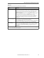
4.4 Results Formats for Standard Record Types . . . . . . . . . . . . . . . . . . . . . . . . . . . . . . . . . . . . .
Inspection Record . . . . . . . . . . . . . . . . . . . . . . . . . . . . . . . . . . . . . . . . . . . . . . . . . . . . . . . . . . . . . . . . . . .
Picture Record . . . . . . . . . . . . . . . . . . . . . . . . . . . . . . . . . . . . . . . . . . . . . . . . . . . . . . . . . . . . . . . . . . . . . . .
Camera Record . . . . . . . . . . . . . . . . . . . . . . . . . . . . . . . . . . . . . . . . . . . . . . . . . . . . . . . . . . . . . . . . . . . . . .
Computed-Point Record . . . . . . . . . . . . . . . . . . . . . . . . . . . . . . . . . . . . . . . . . . . . . . . . . . . . . . . . . .
Computed-Line Record . . . . . . . . . . . . . . . . . . . . . . . . . . . . . . . . . . . . . . . . . . . . . . . . . . . . . . . . . . .
Computed-Circle Record . . . . . . . . . . . . . . . . . . . . . . . . . . . . . . . . . . . . . . . . . . . . . . . . . . . . . . . . .
Computed-Frame Record . . . . . . . . . . . . . . . . . . . . . . . . . . . . . . . . . . . . . . . . . . . . . . . . . . . . . . . . .
Ruler Record . . . . . . . . . . . . . . . . . . . . . . . . . . . . . . . . . . . . . . . . . . . . . . . . . . . . . . . . . . . . . . . . . . . . . . . . .
Arc-Ruler Record . . . . . . . . . . . . . . . . . . . . . . . . . . . . . . . . . . . . . . . . . . . . . . . . . . . . . . . . . . . . . . . . . . . .
Window Record . . . . . . . . . . . . . . . . . . . . . . . . . . . . . . . . . . . . . . . . . . . . . . . . . . . . . . . . . . . . . . . . . . . . .
Point-Finder Record . . . . . . . . . . . . . . . . . . . . . . . . . . . . . . . . . . . . . . . . . . . . . . . . . . . . . . . . . . . . . . . .
Line-Finder Record . . . . . . . . . . . . . . . . . . . . . . . . . . . . . . . . . . . . . . . . . . . . . . . . . . . . . . . . . . . . . . . . .
Arc/Circle-Finder Record . . . . . . . . . . . . . . . . . . . . . . . . . . . . . . . . . . . . . . . . . . . . . . . . . . . . . . . .
Blob-Finder Record . . . . . . . . . . . . . . . . . . . . . . . . . . . . . . . . . . . . . . . . . . . . . . . . . . . . . . . . . . . . . . . . .
OCR-Field Record . . . . . . . . . . . . . . . . . . . . . . . . . . . . . . . . . . . . . . . . . . . . . . . . . . . . . . . . . . . . . . . . . .
Font Record . . . . . . . . . . . . . . . . . . . . . . . . . . . . . . . . . . . . . . . . . . . . . . . . . . . . . . . . . . . . . . . . . . . . . . . . . . .
Proto-Finder Record . . . . . . . . . . . . . . . . . . . . . . . . . . . . . . . . . . . . . . . . . . . . . . . . . . . . . . . . . . . . . . . .
Prototype Record . . . . . . . . . . . . . . . . . . . . . . . . . . . . . . . . . . . . . . . . . . . . . . . . . . . . . . . . . . . . . . . . . . . .
Value-Combination Record . . . . . . . . . . . . . . . . . . . . . . . . . . . . . . . . . . . . . . . . . . . . . . . . . . . . . .
Frame-Pattern Record . . . . . . . . . . . . . . . . . . . . . . . . . . . . . . . . . . . . . . . . . . . . . . . . . . . . . . . . . . . . . .
Correlation Window . . . . . . . . . . . . . . . . . . . . . . . . . . . . . . . . . . . . . . . . . . . . . . . . . . . . . . . . . . . . . . .
Template Record . . . . . . . . . . . . . . . . . . . . . . . . . . . . . . . . . . . . . . . . . . . . . . . . . . . . . . . . . . . . . . . . . . . .
Conditional Frame Record . . . . . . . . . . . . . . . . . . . . . . . . . . . . . . . . . . . . . . . . . . . . . . . . . . . . . . .
Image Processing Record . . . . . . . . . . . . . . . . . . . . . . . . . . . . . . . . . . . . . . . . . . . . . . . . . . . . . . . . .
4.5 Support Variables for Editing . . . . . . . . . . . . . . . . . . . . . . . . . . . . . . . . . . . . . . . . . . . . . . . . . . . . . . .
4.6 Class Data Structures . . . . . . . . . . . . . . . . . . . . . . . . . . . . . . . . . . . . . . . . . . . . . . . . . . . . . . . . . . . . . . . . . .
4.7 Support Variables for Execution and Runtime . . . . . . . . . . . . . . . . . . . . . . . . . . . . . . . . . .
4.8 Control-Variable Indexes . . . . . . . . . . . . . . . . . . . . . . . . . . . . . . . . . . . . . . . . . . . . . . . . . . . . . . . . . . . . .
4.9 Support Variables for Logging Results . . . . . . . . . . . . . . . . . . . . . . . . . . . . . . . . . . . . . . . . . . . .
4.10 Miscellaneous Global Variables . . . . . . . . . . . . . . . . . . . . . . . . . . . . . . . . . . . . . . . . . . . . . . . . . . . . .
4.11 Data Structures for Defining Record Types . . . . . . . . . . . . . . . . . . . . . . . . . . . . . . . . . . . . . .
Chapter 5.
5.1
5.2
5.3
5.4
64
65
66
66
66
67
68
69
69
69
70
70
70
71
71
72
73
73
74
74
75
76
76
76
77
77
78
78
79
79
80
81
82
83
84
84
84
VisionWare Module . . . . . . . . . . . . . . . . . . . . . . . . . . . . . . . . . . . . . . . . . . . . . . . . . . . . . . . . . . . . . . . . . . 87
Preruntime . . . . . . . . . . . . . . . . . . . . . . . . . . . . . . . . . . . . . . . . . . . . . . . . . . . . . . . . . . . . . . . . . . . . . . . . . . . . . . . .
Preruntime Routines for Statements . . . . . . . . . . . . . . . . . . . . . . . . . . . . . . . . . . . . . . . . . . .
Runtime . . . . . . . . . . . . . . . . . . . . . . . . . . . . . . . . . . . . . . . . . . . . . . . . . . . . . . . . . . . . . . . . . . . . . . . . . . . . . . . . . . . .
Adding Statements That Use Vision Records . . . . . . . . . . . . . . . . . . . . . . . . . . . . . . . . . . .
Using Repeat Trees in Statements . . . . . . . . . . . . . . . . . . . . . . . . . . . . . . . . . . . . . . . . . . . . . . . . . .
VisionWare Reference Guide, Rev. A
87
87
88
88
89
v
Table of Contents
Chapter 6.
Examples of Custom Routines
Chapter 7.
VisionWare Statement Routines
Chapter 8.
Descriptions of Vision Module Routines
....................................................
................................................
....................................
91
117
135
Appendix A. Glossary . . . . . . . . . . . . . . . . . . . . . . . . . . . . . . . . . . . . . . . . . . . . . . . . . . . . . . . . . . . . . . . . . . . . . . . . . . . . . . . . . 223
Appendix B. Flow of Control
B.1
B.2
B.3
B.4
B.5
.......................................................................
229
Start-up of AIM . . . . . . . . . . . . . . . . . . . . . . . . . . . . . . . . . . . . . . . . . . . . . . . . . . . . . . . . . . . . . . . . . . . . . . . . .
Loading/Unloading a Module With a Vision Database . . . . . . . . . . . . . . . . . . . . .
Loading . . . . . . . . . . . . . . . . . . . . . . . . . . . . . . . . . . . . . . . . . . . . . . . . . . . . . . . . . . . . . . . . . . . . . . . . . . . . . . .
Unloading . . . . . . . . . . . . . . . . . . . . . . . . . . . . . . . . . . . . . . . . . . . . . . . . . . . . . . . . . . . . . . . . . . . . . . . . . . . .
Editing . . . . . . . . . . . . . . . . . . . . . . . . . . . . . . . . . . . . . . . . . . . . . . . . . . . . . . . . . . . . . . . . . . . . . . . . . . . . . . . . . . . .
Start of Vision Editing . . . . . . . . . . . . . . . . . . . . . . . . . . . . . . . . . . . . . . . . . . . . . . . . . . . . . . . . . . . .
Redraw of a Menu Page . . . . . . . . . . . . . . . . . . . . . . . . . . . . . . . . . . . . . . . . . . . . . . . . . . . . . . . . . .
Refresh of Menu Page . . . . . . . . . . . . . . . . . . . . . . . . . . . . . . . . . . . . . . . . . . . . . . . . . . . . . . . . . . . . .
(*) Execute a Record During Editing . . . . . . . . . . . . . . . . . . . . . . . . . . . . . . . . . . . . . . . . . .
Mouse Events That Are Near Handles . . . . . . . . . . . . . . . . . . . . . . . . . . . . . . . . . . . . . . .
Direct Changing of Record Data . . . . . . . . . . . . . . . . . . . . . . . . . . . . . . . . . . . . . . . . . . . . . . .
When a New Record Is Created . . . . . . . . . . . . . . . . . . . . . . . . . . . . . . . . . . . . . . . . . . . . . . . .
If Another Menu Page Pops Up and Down . . . . . . . . . . . . . . . . . . . . . . . . . . . . . . . . .
Scheduler Is Active . . . . . . . . . . . . . . . . . . . . . . . . . . . . . . . . . . . . . . . . . . . . . . . . . . . . . . . . . . . . . . . . . . . .
Link Time . . . . . . . . . . . . . . . . . . . . . . . . . . . . . . . . . . . . . . . . . . . . . . . . . . . . . . . . . . . . . . . . . . . . . . . . . . . .
Preruntime . . . . . . . . . . . . . . . . . . . . . . . . . . . . . . . . . . . . . . . . . . . . . . . . . . . . . . . . . . . . . . . . . . . . . . . . . . .
Runtime (Cycling Through the Sequence) . . . . . . . . . . . . . . . . . . . . . . . . . . . . . . . . . .
Runtime Execution Routine—vw.eval( ) . . . . . . . . . . . . . . . . . . . . . . . . . . . . . . . . . . . . . . . .
229
230
230
230
230
230
230
232
232
233
234
234
234
235
235
235
235
235
..............................
237
Comments on Notation . . . . . . . . . . . . . . . . . . . . . . . . . . . . . . . . . . . . . . . . . . . . . . . . . . . . . . . . . . . . . . .
Computational Record Type . . . . . . . . . . . . . . . . . . . . . . . . . . . . . . . . . . . . . . . . . . . . . . . . . . . . . . . .
Definition Routine—∗∗∗.cmp.def( ) . . . . . . . . . . . . . . . . . . . . . . . . . . . . . . . . . . . . . . . . . . .
Execution Routine—∗∗∗.cmp.exec( ) . . . . . . . . . . . . . . . . . . . . . . . . . . . . . . . . . . . . . . . . . .
Vision-Tool Record Type . . . . . . . . . . . . . . . . . . . . . . . . . . . . . . . . . . . . . . . . . . . . . . . . . . . . . . . . . . . .
Definition Routine—∗∗∗.vtl.def( ) . . . . . . . . . . . . . . . . . . . . . . . . . . . . . . . . . . . . . . . . . . . . .
Set-Data Routine—∗∗∗.vtl.data( ) . . . . . . . . . . . . . . . . . . . . . . . . . . . . . . . . . . . . . . . . . . . . . .
Execution Routine—∗∗∗.vtl.exec( ) . . . . . . . . . . . . . . . . . . . . . . . . . . . . . . . . . . . . . . . . . . . .
237
237
238
240
242
242
245
245
Appendix C. Template Routines for Custom Record Types
C.1
C.2
C.3
...............................
249
Example Routines for Computational Record Type . . . . . . . . . . . . . . . . . . . . . . . . . .
Definition Routine—ctr.def( ) . . . . . . . . . . . . . . . . . . . . . . . . . . . . . . . . . . . . . . . . . . . . . . . . . . .
Execution Routine—ctr.exec( ) . . . . . . . . . . . . . . . . . . . . . . . . . . . . . . . . . . . . . . . . . . . . . . . . .
Example Routines for Vision-Tool Record Type . . . . . . . . . . . . . . . . . . . . . . . . . . . . . .
Definition Routine—bearing.def( ) . . . . . . . . . . . . . . . . . . . . . . . . . . . . . . . . . . . . . . . . . . . .
Execution Routine—bearing.exec( ) . . . . . . . . . . . . . . . . . . . . . . . . . . . . . . . . . . . . . . . . . . .
249
250
251
253
253
255
Appendix D. Example Routines for Custom Record Types
D.1
D.2
vi
VisionWare Reference Guide, Rev. A
Table of Contents
Appendix E. Custom Combination Records
E.1
E.2
E.3
...................................................
257
How It Works . . . . . . . . . . . . . . . . . . . . . . . . . . . . . . . . . . . . . . . . . . . . . . . . . . . . . . . . . . . . . . . . . . . . . . . . . . .
Execution Routine—The Basic Loop . . . . . . . . . . . . . . . . . . . . . . . . . . . . . . . . . . . . . . . . . .
Common Improvements to the Basic Loop . . . . . . . . . . . . . . . . . . . . . . . . . . . . . . . . .
Important Observations . . . . . . . . . . . . . . . . . . . . . . . . . . . . . . . . . . . . . . . . . . . . . . . . . . . . . . . . . . . . . .
Template Routines for Combination Records . . . . . . . . . . . . . . . . . . . . . . . . . . . . . . . . . .
Definition Routine—cmb.def( ) . . . . . . . . . . . . . . . . . . . . . . . . . . . . . . . . . . . . . . . . . . . . . . . .
Set-Data Routine—cmb.set.data( ) . . . . . . . . . . . . . . . . . . . . . . . . . . . . . . . . . . . . . . . . . . . . .
Execution Routine—cmb.exec( ) . . . . . . . . . . . . . . . . . . . . . . . . . . . . . . . . . . . . . . . . . . . . . . .
257
258
258
259
259
260
262
263
Appendix F. Switches and Parameters
..........................................................
267
Appendix G. Disk Files . . . . . . . . . . . . . . . . . . . . . . . . . . . . . . . . . . . . . . . . . . . . . . . . . . . . . . . . . . . . . . . . . . . . . . . . . . . . . . . 269
Appendix H. Modification of Custom Record Types . . . . . . . . . . . . . . . . . . . . . . . . . . . . . . . . . . . . . . . . 277
H.1
H.2
H.3
Appendix I.
I.1
I.2
I.3
I.4
I.5
Updating Version 2.0 to Version 2.2
Updating Version 2.2 to Version 2.3
Updating Version 2.3 to Version 3.0
..............................................
..............................................
..............................................
277
277
277
.......................................
279
Classes . . . . . . . . . . . . . . . . . . . . . . . . . . . . . . . . . . . . . . . . . . . . . . . . . . . . . . . . . . . . . . . . . . . . . . . . . . . . . . . . . . . .
Record Types . . . . . . . . . . . . . . . . . . . . . . . . . . . . . . . . . . . . . . . . . . . . . . . . . . . . . . . . . . . . . . . . . . . . . . . . . . . .
Modification of Existing Custom Record Types . . . . . . . . . . . . . . . . . . . . . . . . . . .
Creating Custom Record Types . . . . . . . . . . . . . . . . . . . . . . . . . . . . . . . . . . . . . . . . . . . . . . . .
Installing Custom Record Types . . . . . . . . . . . . . . . . . . . . . . . . . . . . . . . . . . . . . . . . . . . . . . .
Data Logging . . . . . . . . . . . . . . . . . . . . . . . . . . . . . . . . . . . . . . . . . . . . . . . . . . . . . . . . . . . . . . . . . . . . . . . . . . . .
Statement Preruntime Routines . . . . . . . . . . . . . . . . . . . . . . . . . . . . . . . . . . . . . . . . . . . . . . . . . . . .
Data Structures . . . . . . . . . . . . . . . . . . . . . . . . . . . . . . . . . . . . . . . . . . . . . . . . . . . . . . . . . . . . . . . . . . . . . . . . .
279
279
279
279
280
280
281
282
Customizer-Related Software Changes
Index . . . . . . . . . . . . . . . . . . . . . . . . . . . . . . . . . . . . . . . . . . . . . . . . . . . . . . . . . . . . . . . . . . . . . . . . . . . . . . . . . . . . . . . . . . . . . . . . . . . . . . . . . . 285
Index of Programs and Statements
.................................................................
291
Index of Global Variables . . . . . . . . . . . . . . . . . . . . . . . . . . . . . . . . . . . . . . . . . . . . . . . . . . . . . . . . . . . . . . . . . . . . . . . . . . . . . 293
VisionWare Reference Guide, Rev. A
vii
Chapter 1
Introduction and Overview
This manual presents a detailed description of the vision control module (the Vision Module) and
the VisionWare Application Module (the VisionWare Module) for the Adept Assembly and Information Management (AIM) software system. This manual is for use by AIM system customizers
who want to provide an interface to application-specific vision operations or special algorithms.
This manual contains detailed information regarding the internal organization of the software, the
data structures, and the Vision database.
An understanding of the information in this document is not required to set up and operate the
AIM system, or to make simple modifications to the operator interface.
For a description of how to operate your AIM system, please see the user ’s guide for your
application module (for example, the VisionWare User’s Guide or AIM PCB User’s Guide).
1.1
Do You Really Need to Read This Manual?
This manual is for use by AIM system customizers who wish to customize aspects of AIM that are
related to vision. Many modifications can be made to the base AIM system; they are detailed in
separate manuals. The common modifications and the manuals that cover them are:
1. Procedural and appearance changes
These apply to the start-up and appearance of the operator interface. These are not specific to
the Vision Module, but rather are common to all AIM applications. See the AIM Customizer’s
Reference Guide.
2. Adding or modifying statements
The basics of creating statements are covered in the AIM Customizer’s Reference Guide.
Requirements for statements that involve vision records as arguments are covered in Chapter
5 of this manual. This chapter describes the VisionWare Module, as opposed to the Vision
Module, including the standard statements and how to use vision arguments in new
statements.
You should probably also read Chapters 1 and 2 of this manual (they are short), but you can
skip over 3. Otherwise, the rest of this manual may be needed only as reference.
3. Adding custom vision operations
This is the purpose of this manual, and you need to read at least some of it. You have come to
the right manual.
VisionWare Reference Guide, Rev. A
1
Chapter 1 - Introduction and Overview
1.2
Prerequisite Background Information
This manual assumes that you are at least a fairly proficient user of an AIM application that uses
the Vision Module. Therefore, you should already be familiar with the contents of the following
user ’s guides:
• VisionWare User’s Guide
This manual describes how to use the AIM VisionWare Application Module.
• The User’s Guide for your AIM application module
If your application module is not VisionWare, you should also be familiar with the user’s
guide for the application you are using, for example, the AIM PCB User’s Guide or the
MotionWare User’s Guide.
• AdeptVision VME User’s Guide
This manual describes all the aspects of the use of the optional AdeptVision VME system.
You need to be familiar with this manual in order to set up and operate the vision system.
In addition, you need to be familiar with the following reference manuals:
• AIM Customizer’s Reference Guide
This manual presents a detailed description of the AIM baseline software. The manual covers
data structures, standard databases, internal organization of the software, and strategies for
customizing the AIM system.
• V+ Reference Guide
This manual describes the V+ robot control and programming system. Since all of the AIM
software is written in the V+ programming language, most customizers find it necessary to
have a good working knowledge of the V+ programming language. In particular, customizers
wishing to make use of the advanced features of the operator interface, or those wishing to
add new statements or strategy routines, find it necessary to understand V +. However,
simple changes to the operator interface (or the addition of new menu pages) can be
accomplished without a knowledge of the V+ programming language.
• AdeptVision VME Reference Guide
This manual describes all aspects of the V+ programming system that pertain to the
AdeptVision VME system. Most customizers who work with the AIM Vision Module find it
necessary to have a good working knowledge of the AdeptVision system. This is most
important when adding new record types that make use of vision primitives.
1.3
Overview of the Aim Vision Module
The AIM Vision Module is a collection of programs and menu pages that maintain and operate on
data in a database to allow vision to be used for inspection or robot guidance. In making any
changes or additions to this module, the system customizer should keep in mind the goals of
simplicity, consistency, and modularity.
The major components of the AIM Vision Module are:
1. A Vision database that contains the data needed for the various vision operations to compute
results at runtime
2
VisionWare Reference Guide, Rev. A
Overview of the Aim Vision Module
2. A Camera database that specifies the physical camera to use, the camera model, various other
camera characteristics, and the camera calibration data
3. Menu files that permit this data to be displayed and edited in a convenient manner (for example, point, click, and drag)
4. Many subroutines that are used in the initialization, editing, execution, and displaying of
vision operation data and results
Vision Database
The Vision database holds the information necessary to perform vision operations. Each record in
the database represents a unique vision operation, containing the data needed to use that
operation to compute results at runtime.
Different types of vision operations require different types of information from the database. To
distinguish one type of vision operation from another, we use the concept of a record type. All the
records of a particular record type use the database record structure the same way and share the
same routines for editing and execution.
Models (prototypes, templates, and fonts) are associated uniquely with each Vision database.
Therefore, each time you unload a module containing a Vision database, all the models associated
with it are deleted from the system. When you load a module containing a Vision database, the
model files for the new Vision database are loaded from disk. This can take a considerable amount
of time, so it is expected that you will not be loading and unloading Vision databases frequently.
Menu Summary
This section describes the menu files that are part of the Vision Module.
• VISGEN.MNU
Contains the menu pages for displaying and editing the following types of records in the
Vision database:
Picture
Inspection
Computed Point, Line, Circle, and Frame
Frame Pattern
Value Combination
Prototype
Template
These are general operations that do not belong in the vision-tool or OCR menu files. Menu
pages for vision operations added by customizers should be kept in separate files.
• VISINI.MNU
Contains the menu pages for displaying and editing the Vision Initialization database. This
database defines custom convolutions and morphological operations.
• VISLOG.MNU
Contains the menu pages for displaying and setting up Data Logging operations.
• VISOCR.MNU
Contains the menu pages for displaying and editing the OCR-related records in the Vision
database.
VisionWare Reference Guide, Rev. A
3
Chapter 1 - Introduction and Overview
• VISTOOLS.MNU
Contains the menu pages for displaying and editing the following vision-tool records in the
Vision database:
Ruler
Arc Ruler
Window
Point, Line, and Arc/Circle Finders
Blob Finder
Prototype Finder
Correlation Window
• VISRES.MNU
Contains menu pages for results and data plotting.
• VISUTIL.MNU
Contains various general-purpose vision-related menu pages, such as the Live Video pop-up
window.
• VISNEW.MNU
Contains menu pages with choices of new vision operations.
• VSFRM.MNU
Contains the menu pages for displaying and editing the Conditional Frame records in the
Vision database.
• VIMAGEP.MNU
Contains the menu pages for displaying and editing image processing operations (i.e.,
records of the Image Processing record type) in the Vision database.
• VISCAL.MNU
Contains the menu pages for defining and performing camera calibrations in the Vision
database.
• VISCAM.MNU
Contains the menu pages for displaying and editing the Camera database.
Routines
A knowledge of the routines used in the Vision Module is not necessary unless you intend to
customize the system.
The different kinds of routines are described below. Some routines need to be modified or created
by system customizers. Other routines, called standard routines, are included in the AIM system
for use as provided. Detailed descriptions of these routines are provided in Chapter 8.
NOTE: All AIM routines are written in the Adept V+ programming
language.
4
VisionWare Reference Guide, Rev. A
Overview of the Aim Vision Module
• Standard editing support routines
These routines support the creation and editing of record data from a menu page. This
includes monitoring of changes in data values, and manipulation of graphic shapes using the
mouse.
• Standard routines for use while executing records
These routines are called from the routines that execute vision records. They may be useful
when creating custom record types. (More information on these routines is provided later.)
• Standard runtime scheduler routines
These routines are normally called by the application-specific runtime scheduler to control
the execution of statements and vision records. (Statement routines are part of the VisionWare
application module—see Chapter 5.)
• Standard graphics routines
These routines provide high-level functionality when there is a need to display vision tools
during editing or to display the results after execution.
• Record-type specific routines
These routines provide support for specific record types. Routines already exist for the many
built-in record types supplied with the Vision Module. For new record types, however,
routines need to be written by the customizer, following the functional specifications for the
routines given in Chapter 6.
VisionWare Reference Guide, Rev. A
5
Chapter 2
General Concepts
The Vision Module is designed as an integral part of AIM to provide a means for specifying and
performing a wide variety of vision operations for inspection, measurement, and robot guidance.
The threefold focus of the design is for easy and logical specification of operations, efficient
execution of them, and natural direction of the results to other operations or to output signals.
Understanding the Vision Module is best accomplished by keeping in mind these three main
functional components: data, execution, and results. This chapter describes these elements and
how they combine to perform the vision operations.
The Vision Module contains a fairly complete set of built-in vision operations for performing the
vast majority of applications. However, customization is allowed and expected, and is achieved
primarily by creating new types of vision operations. See Chapter 3 for more details.
2.1
Vision Operations and Vision Records
A vision operation is the basic functional unit in the Vision Module. It consists primarily of data
(stored in the Vision database), an execution routine, and a specification of how the results may be
used.
The “record type” is the key value (in the Vision database records) that distinguishes one type of
vision operation from another. For example, the record type determines which execution routine is
used for a specific vision operation and how the results of the operation may be used.
The record type is one of the data items in each record in the Vision database. Thus, a vision record
provides all the information needed to perform a vision operation, and one can often use the terms
“vision record” and “vision operation” interchangeably. For example, the vision operations “Line
Finder”, “Point Finder”, and “Computed Circle” all have different record types.
The term “vision record” refers to the data needed for a vision operation and consequently to the
editing and manipulation of that data. The term “vision operation” refers to the utilization of the
information in the vision record—namely, for execution. For example, when editing a vision
record, one would say that one selects the vision operations that will be used to compute the
results.
2.2
Data
As mentioned above, the data for a vision operation is kept in a vision record. The data structure
within the record is composed of fixed-use fields and variable-use fields. That is, some fields serve
the same purpose for all records, while the use of other fields depends on the record type. When
AIM is started up, all the numeric and string data in these records are copied into two global
arrays called the “data arrays”. For speed and efficiency, these global arrays are used extensively,
avoiding accesses to the actual database.
VisionWare Reference Guide, Rev. A
7
Chapter 2 - General Concepts
There is a special group of fields in the database used for keeping track of the “source records” of
the record. Depending on the record type and evaluation method, these source records may have
different purposes, but they always mean one very important thing to the Vision Module: that the
records specified there must be executed prior to execution of the record itself. The source record
names are linked automatically during editing and preruntime to the corresponding record
numbers. These records are also called simply the “sources” for this record and for the vision
operation it represents. For example, a “point-line distance” inspection record requires a point and
a line. The point record and the line record are considered sources for the inspection record.
2.3
Execution
A vision operation is performed by “executing” a vision record. There is an execution routine for
each record type. The execution routine uses the data in the “data arrays” to compute results.
Pertinent numeric and string values are stored in global arrays called the “results arrays”. In
addition, the routine may accumulate statistics or draw graphics depicting the operation and its
results.
When a sequence is started (that is, at preruntime), the statements in the sequence are scanned for
the presence of arguments that are the names of records from the Vision database. These
arguments represent vision operations whose results are presumably needed for the execution of
the statement. Therefore, each of these vision operations will need to be performed at runtime. To
do this, the statement routine will “evaluate” the named vision records.
NOTE: Evaluation of a vision record consists of (1) evaluating all the
source records for the record and then (2) executing the vision record
itself. Note that this definition is recursive—that is, the evaluation process
works its way down the tree of needed records, finds the ones that are
needed first, executes them, and then works its way back up the tree. In
this way, a record is executed only when all its source records have been
evaluated. (The Vision Module contains the routine vw.run.eval2( ) for
evaluating vision records from statement routines.)
To prepare for this evaluation process, a list is created at preruntime that contains all the vision
records needed for each statement argument. This list is also specially ordered to provide the most
overlap of the Vision and V+ processing when possible. Then, when the standard routine
mentioned above is called to evaluate a vision argument, it can execute the vision records listed
with minimal overhead.
When a vision record is executed, an execution routine associated with the record type for the
record is used. For custom record types, the routine name must be specified when the record type
is defined.
2.4
Results
After a vision operation is performed (that is, a vision record is executed), there are usually results.
These are stored in the global results arrays—vw.res[,,] and $vw.res[,,]. The stored results are
available for use by other vision operations.
In addition, statistics may have been collected for any number of the values computed by a record.
Inspection records automatically collect statistics for the result being tested (unless that option is
disabled during editing). For any inspection record, the result being tested, the pass/fail status of
the result, and their recent statistical histories (along with charts) are available for monitoring
during runtime via the “Show/Vision Results” pull-down menu at the top of the screen.
8
VisionWare Reference Guide, Rev. A
Classes
For custom record types, a pair of standard routines can be called from the custom record-type
routines to facilitate collecting the same kinds of statistics. The statistical information will then be
available automatically for display in the same way as for the standard inspection operations. See
the section “Accumulating Statistics” on page 45 for details on how to use this feature.
2.5
Classes
A standard format is defined for storage of some common types of results in the results array. For
example, both the Line Finder and Computed Line vision operations produce a line as a result.
Therefore, they both use the standard format for representing line results in the results array. In
this way, the results of different operations can be used interchangeably as a source for other
operations, such as computing a point.
When a vision operation produces data for a line and stores it in the results array (as described
above), that vision operation is said to belong to the line “class”. Likewise, there are classes for
points, circles, and vision frames.
When a record type is defined, the types of source records needed are specified by naming their
classes. Then, when the user needs to select a source record, the Vision Module can provide a list
of the existing records in the required class. If there are none, it can go straight to a new record
page for that class.
For computing a point from two lines, the Computed Point vision operation needs, as sources, two
LINEs. That is, it needs two members of the line class. In this document and on the menu pages,
you will sometimes see the names of classes capitalized. In that case, they are being used as
abbreviations. For example, “LINE” is short for “a member of the line class”. Likewise, “POINT”
and “VISION FRAME” are commonly used to represent members of the point and vision-frame
classes, respectively.
A vision operation often can belong to several classes. However, it must belong to at least one class
in order to be used as a source for other operations.
2.6
Calibration
Calibration is the process that determines the exact scale and position of the camera image. By
default, the Vision Module initializes all virtual cameras to have a one-to-one X-Y ratio, a scale
factor of one millimeter per pixel, and a coordinate frame fixed at one corner of the camera image.
Calibration of the vision system is necessary in the following situations:
1. Measurements are to be reported in real-world units such as millimeters or inches. Otherwise, all measurements will be in pixels.
2. Positions are needed relative to a world coordinate frame. Otherwise, positions are relative to
its local camera coordinate frame. (You must have a robot to establish the coordinate frame.)
3. Measurements are needed across multiple camera images.
The Vision Module provides a calibration procedure, similar to ADV_CAL (Advanced Camera
Calibration) with enhanced functionality, that can be used without exiting AIM. The VisionWare
User’s Guide describes the procedure fully.
If your application uses a motion device, it may need to be calibrated. This procedure is fully
described in the MotionWare User’s Guide.
VisionWare Reference Guide, Rev. A
9
Chapter 2 - General Concepts
NOTE: VisionWare with Motion is no longer a valid system configuration.
Instead, use MotionWare with Vision.
If vision position information is needed in terms of the world coordinate system, you will need to
calibrate the appropriate physical camera(s) with a robot (or motion system of some sort). This
procedure also can be performed within AIM.
10
VisionWare Reference Guide, Rev. A
Chapter 3
Customization
Customization of the Vision Module consists primarily of the following activities:
• Adding new types of vision operations (that is, new record types in the Vision database),
which the user can edit and execute.
This chapter provides instructions on adding a new record type.
• Adding new statements to the Statement database.
Adding new statements is a general capability of AIM and is not specific to vision. Thus, you
should refer to the AIM Customizer’s Reference Guide for detailed information on adding new
statements. Some examples related to vision are presented in this manual. See Chapter 5 for
information on the VisionWare application module.
This chapter contains brief descriptions of the routines that may be used or created during
customization.
This chapter also contains many sections that are useful for reference when needed but may be
confusing if included in the first reading of the manual. Therefore, if you are reading this chapter
for the first time, be selective and skip sections that seem too detailed to be useful to you.
3.1
Database Identification Numbers
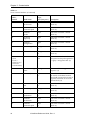
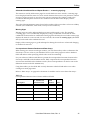
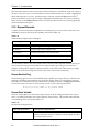
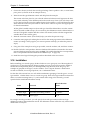
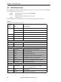
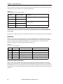
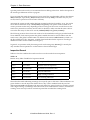
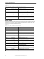
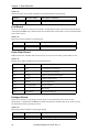
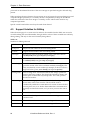
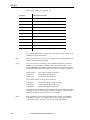
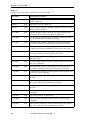
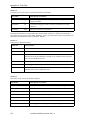
AIM routines refer to databases by their respective identification numbers. Table 3-1 lists all the
databases unique to the Vision Module, their identification numbers, and the global variables that
can be used to refer to the databases.
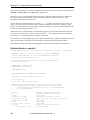
Table 3-1
Database Identification Numbers
Resource
Name
Camera
Vision
Type Variable,
Database Variable,
Module File Ext.
Type,
Number
Description
vc.ty
vc.db[TASK( )]
.vc
31
Defines the parameters and calibration for any
cameras used by vision.
Global database is vcamvw.db
vi.ty
vi.db[TASK( )]
.vi
30
Defines the vision processes used in inspections
and robot guidance.
No global database.
VisionWare Reference Guide, Rev. A
11
Chapter 3 - Customization
NOTE: Whenever possible, use the variables listed in Table 3-1 in place of
explicit database numbers. Future AIM systems may use different
numbers to refer to the databases, but the variable names will be retained
with appropriate values. The only situation where you must use explicit
database numbers is when defining new sequence statements. Refer to
the AIM Customizer’s Reference Guide.
3.2
Adding New Record Types
This section describes how to add a new record type to the Vision Module. We begin by describing
the major components of a record type. Your needs, in terms of these components, will determine
how you implement your new record type.
Why Do You Need a Custom Record Type?
You probably need a custom record type because you need some functionality that doesn’t exist in
the standard record types. Or, if it does exist, you may want to combine the functions of several
record types into one. In either case, you need to clearly identify the functionality required before
implementing the new record type.
VisionWare provides a great deal of flexibility and functionality. Be prepared to recognize
functionality you don’t need as you read this manual, and skip over those sections.
Basic Function and Components of a Record Type
The main function of a vision record is its execution, but the input data and output results are also
key components. The record type provides a way of identifying a common purpose and format for
using a vision record. That is, a record type defines, for every record of that type, the structure of
the data, what happens at execution time, and the format of the results. Thus, there are three basic
aspects or components of a record type: data, execution, and results.
For example, the “Line Finder” standard record type consists of the following three key elements
(simplified a bit for illustration):
Data:
Picture to operate in
Position of the Line Finder in the picture
Parameters needed for the Line Finder
Execution:
Perform VFIND.LINE tool in designated picture
Results:
A LINE, defined by its angle and a point on the line
Percent of edges found
Maximum error distance of edges found from line
Was the operator off the screen at all?
There can be many other supporting aspects to these three main elements, but for now we will
concentrate on understanding the basics of a new record type.
How a Record Type Is Defined
Record types are defined in the Vision Module by the following:
• A unique identifying number (custom record types start at 100)
• A specific format for data usage within a database record
12
VisionWare Reference Guide, Rev. A
Adding New Record Types
• An AIM menu page for editing database records
• A set of subroutines to be used for editing, execution, etc.
• A set of numeric and string descriptors defining various characteristics of the record type
Most of this information is set forth in a routine written by the system customizer, called the
record-type definition routine. This and the other custom routines are fully defined in Chapter 6,
but their basic functions are described in the section “Customization Routines” in this chapter.
Template and sample versions of these routines for some typical operations are presented in
Appendixes C and D, with V+ code versions available in the public file VISTMPLS.V2. Most likely,
one of these will be able to serve as a basis for developing your own record-type routines.
The details of the Vision database are presented before describing the actual routines.
VisionWare Reference Guide, Rev. A
13
Chapter 3 - Customization
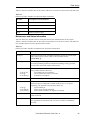
3.3
Vision Camera Database
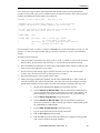
Table 3-2
Vision Camera Database
Field #,
Variable
Field Name
Type,
Size [Array Size]
Description
0
cc.name
name
name
15
A standard AIM name that
uniquely identifies a vision
operation. This name is referenced
in sequence statements. (This field
is typically not changed by custom
routines.) (1)
1
cc.update
update date
date/time
4
The date when this record was last
modified. This field is
automatically set to the current
date when the record is edited.
2
cc.device
device
byte
1
This field is not used by the Vision
Module or by VisionWare. It is
reserved for future use.
3
cc.page.name
menu page name
name
15 [2]
The name of the menu file, and the
name of the record in the file, to use
when displaying and editing this
record. (This field is typically not
accessed by custom routines.)
4
vc.desc
description
string
60
A comment field that contains a
one-line description of the vision
camera’s setup.
5
vc.modes
(vc.mode.num=
Number of
elements in the
array)
modes
real
4 [16]
Available for use as general
parameters for each record type.
See Table 3-3 for variables used as
indexes into the vc.modes array.
6
vc.cam.cal
cal array
real
4 [21]
The vision camera calibration
array. See the AdeptVision Reference
Guide for details on calibration
arrays.
7
vc.pix.to.pmm
pixel-to-pmm array
real
4 [9]
Raw pixels to perspective
millimeters. The vision system
applies this transformation when
returning results to the application
program in millimeter coordinates.
14
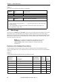
VisionWare Reference Guide, Rev. A
Vision Camera Database
Table 3-2
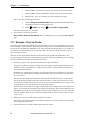
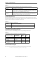
Vision Camera Database (Continued)
Field #,
Variable
Field Name
Type,
Size [Array Size]
Description
8
vc.pmm.to.pix
pmm-to-pixel array
real
4 [9]
Perspective millimeters to raw
pixels. The vision system uses this
transformation to convert userspecified millimeter coordinates
(such as the start of a ruler) to
pixels.
9
vc.to.cam
to.cam
transform
48
A calibration transform for a fixedmount camera’s vision reference
frame or robot-mounted camera’s
vision reference frame.
10
vc.disk.loc
vc.tool.offset
known.dot or
tool.offset
transform
48
Part of the calibration transform.
vc.disk.loc—Doubles as a known
dot location.
vc.tool.offset—Set to be the
average tool offset.
11
vc.belt.name
belt record name
string
15
The name for the conveyor record.
(1)
12
vc.belt.rec
[belt record]
integer
2
The number of a conveyor record
in the Conveyor database
corresponding to the name in the
field “belt record name”.
13
vc.loc1
(vc.loc1 =
vc.away.loc =
vc.nominal.loc)
location1
transform
48
Start of the motion block for a
“lefty” configured robot. (5)
14
location1 strategy
name
string
1
The name of the strategy routine or
sequence. (2)
15
[location1]
byte
1
Start of a standard motion block for
the motion to the basis location.
(First field of motion block with no
approach. Fields 15–25 are in the
motion block.) (3)
16
location1 motion
bits
byte
1
Part of the “location1” motion
block. (4)
17
location1 speed
integer
2
Part of the “location1” motion
block. (4)
18
location1
acceleration
byte
1
Part of the “location1” motion
block. (4)
VisionWare Reference Guide, Rev. A
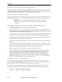
15
Chapter 3 - Customization
Table 3-2
Vision Camera Database (Continued)
Field #,
Variable
Field Name
Type,
Size [Array Size]
Description
19
location1
deceleration
byte
1
Part of the “location1” motion
block. (4)
20
location1
rotational speed
byte
1
Part of the “location1” motion
block. (4)
21
location1
profile
byte
1
Part of the “location1” motion
block. (4)
22
[location1
sequence]
byte
1
Part of the “location1” motion
block. (4)
23
location1
configuration
byte
1
Part of the “location1” motion
block. (4)
24
location1 type bits
integer
2
Part of the “location1” motion
block. (4)
25
[location1 frame]
integer
2
Part of the “location1” motion
block. (4)
26
vc.loc2
(vc.loc2 =
vc.nom.loc.rty=
vc.start.loc=
vc.actual.frame)
location2
transform
48
A transformation that defines the
start point for this path segment for
a “righty” configured robot. (5)
27
location2 strategy
name
string
1
The name of the strategy routine or
sequence. (2)
28
[location2]
byte
1
Start of a standard motion block for
the motion to the basis location.
(First field of motion block with no
approach. Fields 28–38 are in the
motion block.) (3)
29
location2 motion
bits
byte
1
Part of the “location2” motion
block. (4)
30
location2 speed
integer
2
Part of the “location2” motion
block. (4)
31
location2
acceleration
byte
1
Part of the “location2” motion
block. (4)
32
location2
deceleration
byte
1
Part of the “location2” motion
block. (4)
33
location2
rotational speed
byte
1
Part of the “location2” motion
block. (4)
16
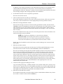
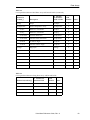
VisionWare Reference Guide, Rev. A
Vision Camera Database
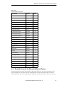
Table 3-2
Vision Camera Database (Continued)
Field #,
Variable
Field Name
34
Type,
Size [Array Size]
Description
location2 profile
byte
1
Part of the “location2” motion
block. (4)
35
[location2
sequence]
byte
1
Part of the “location2” motion
block. (4)
36
location2
configuration
byte
1
Part of the “location2” motion
block. (4)
37
location2 type bits
integer
2
Part of the “location2” motion
block. (4)
38
[location2 frame]
integer
2
Part of the “location2” motion
block. (4)
39
vc.scratch.loc
scratch loc
transform
48
A transformation that defines the
scratch location start point for
robot motions. (5)
40
scratch loc strategy
name
string
1
The name of the strategy routine or
sequence. (2)
41
[scratch loc]
byte
1
Start of a “scratch loc” motion
block. (First field of “scratch”
motion block with no approach.
Fields 28–38 are in the “scratch”
motion block.)(3)
42
scratch loc motion
bits
byte
1
Part of the “scratch loc” motion
block. (4)
43
scratch loc speed
integer
2
Part of the “scratch loc” motion
block. (4)
44
scratch loc
acceleration
byte
1
Part of the “scratch loc” motion
block. (4)
45
scratch loc
deceleration
byte
1
Part of the “scratch loc” motion
block. (4)
46
scratch loc
rotational speed
byte
1
Part of the “scratch loc” motion
block. (4)
47
scratch loc profile
byte
1
Part of the “scratch loc” motion
block. (4)
48
[scratch loc
sequence]
byte
1
Part of the “scratch loc” motion
block. (4)
49
scratch loc
configuration
byte
1
Part of the “scratch loc” motion
block. (4)
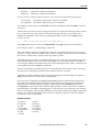
VisionWare Reference Guide, Rev. A
17
Chapter 3 - Customization
Table 3-2
Vision Camera Database (Continued)
Field #,
Variable
Field Name
50
51
Type,
Size [Array Size]
Description
scratch loc type bits
integer
1
Part of the “scratch loc” motion
block. (4)
[scratch loc frame]
integer
2
Part of the “scratch loc” motion
block. (4)
Notes:
1.
2.
3.
4.
5.
Mark database as updated if this value is changed.
Field in motion block, not first; mark database as updated if this value is changed.
First field of motion block, no approach.
Field in motion block, not first.
Field is edited if defined during walk-thru training; basis location for robot motion
block.
Table 3-3
Variables Used as Indexes Into the vc.modes Array
Variable
Index
Number
Description
vc.md.vsys
0
Vision system number
vc.md.flags
1
Mode flags for camera calibration (see below).
Name
Value Description
vc.flg.pitch ^H400 Sets vision Z-axis direction (camera/tool
relationship).
vc.flg.persp ^H800 Sets use of perspective calibration
transformation.
vc.md.max.err
2
Max error when using basic calibration.
Note:
Fields 3 through 15 are reserved for future use.
3.4
Record Structure of the Vision Database
Each record in the Vision database defines a vision operation. Each record, regardless of record
type, has the same field structure (see Table 3-4). However, unlike other AIM databases, some of
the record fields have a “variable” usage. That is, the interpretation of those fields depends on the
record type. For example, the Line Finder record type may use one of the elements of the “modes”
array as the edge strength threshold, whereas the Picture record type may use the same “modes”
element as the video gain.
18
VisionWare Reference Guide, Rev. A
Record Structure of the Vision Database
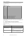
All the record fields are listed and summarized in Table 3-4, in the order in which they occur
within a record. The data in a record can be accessed from an application program by using the V+
variable names shown in Table 3-5. Alternate variables are shown Table 3-7.
Table 3-4
Record Definition for the Vision Database
Field #,
Variable
Field Name
Type,
Size [Array Size]
Description
0
cc.name
name
name
15
A standard AIM name that uniquely
identifies a vision operation. This name is
referenced in sequence statements. (This
field is typically not changed by custom
routines.) (1)
1
cc.update
update date
date/time
4
The date when this record was last
modified. This field is automatically set to
the current date when the record is edited.
(3)
2
cc.device
device
byte
1
This field is not used by the Vision Module
or by VisionWare. It is reserved for future
use. (4)
3
cc.page.name
menu page
name
name
15 [2]
The name of the menu file, and the name of
the record in the file, to use when
displaying and editing this record. (This
field is typically not accessed by custom
routines.) (3)
4
vi.rec.type
record type
byte
1
A unique number (in the range 100 to 255,
inclusive) that identifies the type of record.
(0 to 99 are reserved for Adept records.)
This is specified when the record-type
definition routine is called. It is not
normally modified by custom routines. (2)
5
vi.eval.method
eval method
byte
1
A value (in the range 1 to 255, inclusive)
used to indicate the specific evaluation
method for a record when there is more
than one method for the record type. (For
example, this may indicate that a
Computed Point is to be computed using
the intersection of two LINEs, as opposed
to being centered between two POINTs.) (5)
6
vi.modes
(vi.mode.num=
Number of
mode values)
modes
real
4 [16]
Available for use as general parameters for
each record type. See Table 3-5 for variables
that can be used as indexes into the
vi.modes array. (5)
VisionWare Reference Guide, Rev. A
19
Chapter 3 - Customization
Table 3-4
Record Definition for the Vision Database (Continued)
Field #,
Variable
Field Name
Type,
Size [Array Size]
Description
7
vi.shape
shape
real
4
If the record type is a “shape” type, this
indicates what specific shape parameters
will follow in the “shape description” field.
For example, line rulers and arc rulers have
different shapes. (5)
8
vi.shape.desc
(vi.shape.num=
Number of
shape values)
shape
description
real
4 [6]
If the record type is a “shape” type, this
holds parameters that define the shape.
Refer to Table 3-6 for examples (the specific
items may vary with different record types
and shapes). (6)
9
vi.flags
flags
byte
1
A bit field having bits 1 through 4 available
for general use. Bit 5 is used to force an
angle of 0 degrees for a normally rotatable
tool. Bit 6 is used for the ✔ Repeat
indicator. Bit 7 is used for the ✔ TopLevel
indicator. Bit 8 is used for the ✔ Show at
runtime indicator. (7)
10
vi.num.sources
num sources
byte
1
Number of sources for the “eval method”
specified in the record. This is set
automatically when the “eval method” is
changed. It is determined using an array
that is set up when each record type is
defined. This count does not include
source 0, which is reserved for a vision
frame. (This field is normally managed by
the Vision Module.) (2)
11
vi.src.recs
source rec
integer
2 [9]
Source record numbers determined by
linking the source names in the “source rec
name” array. The first element in the array
(index 0) is always the vision frame source.
(This field is normally managed
completely by the Vision Module.) (2)
20
VisionWare Reference Guide, Rev. A
Record Structure of the Vision Database
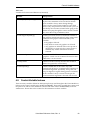
Table 3-4
Record Definition for the Vision Database (Continued)
Field #,
Variable
Field Name
Type,
Size [Array Size]
12
vi.src.rec.name
source rec
name
name
15 [9]
The names of the records that must be
executed prior to this record being
executed. (This field is normally managed
completely by the Vision Module.)
• The first element in the array (index 0)
is always the name of the vision
frame.
• For “vision tool” record types, the
second element (index 1) is reserved
for a Picture record.
• For “combination” record types, the
second element (index 1) must be the
top of the repeat tree for that record.
• The uses of the other source-record
references must be specified in the
record-type definition routine.
When defining a record type, you will
indicate which classes of record types will
be allowed in each array element, given a
particular evaluation method. (Each class
indicates the kind of results produced by a
source record type.) (2)
13
vi.str.data
(vi.str.num=
Number of data
strings)
string data
string
30 [2]
Multipurpose data strings (like the
“modes” array) used as general parameters
for each record type. (For example, the
Prototype records store the prototype
name in this field.) (5)
Description
Notes:
1. Mark the database as updated if this value is changed. Meaning is the same for all
records.
2. Meaning is the same for all records.
3. Same as Note 2, except use of the field is restricted to Adept routines.
4. Field is not used.
5. Meaning can depend on the record type.
6. Meaning is “fixed” (the same for all records) for some record types, and “variable”
(can depend on the record type) for some record types.
7. Four bit flags are fixed; four bit flags are variable.
VisionWare Reference Guide, Rev. A
21
Chapter 3 - Customization
Table 3-5
Variables Used as Indexes Into the vi.modes Array
Variable Name
Interpretation
vi.md.0
Mode 0
vi.md.1
Mode 1
vi.md.2
Mode 2
vi.md.3
Mode 3
vi.md.4
Mode 4
vi.md.5
Mode 5
vi.md.6
Mode 6
vi.md.7
Mode 7
vi.md.8
Mode 8
vi.md.9
Mode 9
vi.md.10
Mode 10
vi.md.11
Mode 11
vi.md.12
Mode 12
vi.md.13
Mode 13
vi.md.14
Mode 14
vi.md.15
Mode 15
Table 3-6
Variables and Meanings for the Elements in the vi.shape.desc (Shape Description) Array
Variable Name
Index
Number
Description
vi.shp.x
0
X coordinate of position (for example, arc center)
vi.shp.y
1
Y coordinate of position
vi.shp.dim1
2
Dimension 1 — A linear dimension (for example, width)
vi.shp.dim2
3
Dimension 2 — Another linear dimension (for example,
length)
vi.shp.a0
4
Angle 1 — An angle (for example, starting angle of arc)
vi.shp.an
5
Angle 2 — Another angle (for example, ending angle of arc)
22
VisionWare Reference Guide, Rev. A
Memory-Resident Data Structures
Table 3-7
Alternate V+ Variables for Vision Records
Variable Name
Alternate Name
Used For
vi.shape
vi.variety
Inspections (2nd eval method)
vi.shape.desc
vi.limits
Inspections
3.5
vi.shp.x
vi.lim.nom
Nominal value
vi.shp.y
vi.lim.min
Minimum value
vi.shp.dim1
vi.lim.max
Maximum value
vi.shp.dim2
vi.lim.lo
Low warning limit
vi.shp.a0
vi.lim.hi
High warning limit
Memory-Resident Data Structures
Although the permanent data storage for vision operations is in the Vision database, other data
structures are kept in memory for speed and efficiency during editing and at runtime.
Data Arrays
Two of the most important of these data structures are the data arrays: vw.data[,,] and $vw.data[,,].
These arrays, which have the database number as their primary index and the physical record
number as their secondary index, contain all the data from the records in the Vision database. In
addition, the arrays contain some maintenance information used by the Vision Module and,
optionally, some data computed uniquely for each record prior to editing or runtime.
For most record types, reading and setting of record data values are handled exclusively through
these arrays. AIM handles all reading and writing of the actual database records. However, since
the menu pages used for editing refer to a data value by its database field and index, you must
know the correspondence between the database and the arrays. See “Correspondence Between
Database and Data Arrays” on page 35.
Results Arrays
Two other key data structures used by vision operations are the results arrays: vw.res[,,] and
$vw.res[,,]. These arrays, which also have the database number as their primary index and the
physical record number as their secondary index, hold the results of executing a record. These
results can then be used by other records for computing their own results.
If you want the results of your record type to be generally available for a specific use (for example,
as a LINE), you need to put your results in the arrays in specific slots (for example, X, Y, angle,
cosine, and sine as the first five values in vw.res[,,]). This makes it possible for your record type to
be considered as a member of a particular “class” (the line class, for example). Classes are
described in more detail later in this chapter.
VisionWare Reference Guide, Rev. A
23
Chapter 3 - Customization
Variables for Array Indexes
For each value in the data arrays, there is a standard variable name that can be used to specify the
array index when initializing, editing, drawing, or executing your record type. For example,
element vw.data[vi.db[TASK( )],n,vs.src.1] contains (for database record number “n”) the record
number for source 1. As another example, for records that are in the point class, the variables vw.x
and vw.y can be used as the indexes into the results array for the X and Y coordinates, respectively,
of the point.
The predefined variable names are naturally very general and terse. You are encouraged to define
variables that are more descriptive, based on your particular usage of the array elements. (These
variables are defined in the record-type definition routine.) For a complete list of the variables
already defined for each of the standard record types, see Chapter 4.
3.6
Division of Effort
When customizing a general system, it is important to understand clearly which general
capabilities are managed automatically and which specific actions and computations need to be
managed with custom data and routines. This section explains where the various responsibilities
lie.
AIM and the Vision Module always have primary control of the system. When operator input of
some sort is made (mouse click, number entry, menu selection), the Vision Module will either
handle it completely, preprocess it somewhat and pass it through a custom routine, or let it be
completely managed by custom routines.
For example, editing actions that are fairly common or involve graphics (that is, where consistency
is important) are controlled by the Vision Module. Management of runtime preparation and
execution also is controlled by the Vision Module.
As you create a new record type, you are given the opportunity to do a great deal of customization
in the form of custom routines you can write. Please note that many of these routines are optional
and may not be needed for your record type. Also, some of these routines can operate in several
different modes, some of which can be ignored.
The following is a list of the key functions automatically handled by the system. (Note, however,
that there are often opportunities for special actions for specific record types.)
• Checking new record names (including source names) for validity.
• Linking source names to record numbers.
• Display and selection of valid source records.
• Vision frame and picture management.
• Creation and deletion of records.
• Creating/deleting/saving/loading prototypes and fonts.
• Drawing and editing tools and graphics. (The system manages all drawing, processing of
mouse clicks, and dragging of handles. It also erases a graphic before a change and redraws it
afterwards.)
• Execution order and task usage (overlap of motion, vision, and AIM).
The following list shows the functions and information that you are expected to provide, and
actions that you can influence, for each custom record type.
24
VisionWare Reference Guide, Rev. A
Customization Routines
• Initialization at AIM start-up
Definition of custom record types and classes.
• Editing and menu-page management (optional)
You provide a routine that will be called each time:
A different record is selected for editing.
The menu page is about to be redrawn.
The menu page is about to be refreshed.
A data value is changed.
A significant window/mouse event happens (for example, mouse down on handle, delete
record selected, etc.).
• Drawing graphics for editing (optional)
You provide a routine that draws a graphic for editing based on the data in the data arrays.
• Execution routine
You provide a routine that performs the desired actions or computations based on the data
arrays and puts the results in the results arrays.
• Preruntime execution (optional)
You provide a routine that is called.
• New record setup—initializing data values (optional)
You provide a routine that is called when a new record is created. This routine assigns default
data values to the data arrays. They are then used to initialize the new record.
The routines mentioned above are outlined briefly in the next section; full descriptions are
presented in Chapter 6.
3.7
Customization Routines
The routines described here are to be written by the customizer, if needed, and given unique
names. The names you assign are specified within the record-type definition routines. The
appropriate routine will then be used for each record type during editing or execution.
NOTE: The routine names used here (and throughout this manual) are
intended to be generic names indicating the function of the routines. You
must assign unique names to the routines you create.
A brief synopsis of each routine appears below; a more complete description is given in the
following sections. For a complete description, however, you should refer to the “dictionary
pages” in Chapter 6. For examples, see the routines in the file VFINDERS.V2, which contains the
actual routines used for the Line Finder, Point Finder, and Arc Finder record types. (The definition
VisionWare Reference Guide, Rev. A
25
Chapter 3 - Customization
routines for these record types are in VFINDERS.OV2.) Also, see Appendix C for template routines
and Appendix D for corresponding example routines.
Routine
Name
Use
Record-type
definition
vrec.def
Define the record-type characteristics, including the
names of the routines to be used when editing or
executing records of the record type.
Execution
vrec.exec
Performs computations based on the data arrays,
and puts the results in the results arrays.
Set-data
vrec.set.data
(optional)
Called to set data values when a record is created,
when it is initialized from the database, or at
preruntime for execution efficiency.
Edit
vrec.edit
(optional)
Called to handle menu-page and editing
initialization and user actions. This routine is needed
only for special handling of parameter editing.
Edit shape
drawing
vrec.draw
(optional)
Draws a shape using the data in the numeric data
array. This routine is needed only if doing graphical
editing of the shape parameters. (It is called around
mouse moves to erase and draw the shape.)
Menu-page
refresh
vrec.refresh
(optional)
Called when the menu page is refreshed. (This
routine should update any control variables or
database values that are displayed by the menu
page.)
Record-Type Definition Routine
When creating a new record type, the record-type definition routine should be written first, or in
conjunction with the execution routine. Unless your record type is very simple, you probably will
find that revisions will be made to this routine as the execution routine is written and as the menu
page for editing is created.
This routine has output parameters that need to be filled with information describing the record
type and with routine names to be used with the record type. The definition routine must do the
following:
• Define descriptive variables to be used as indexes for the data and results arrays.
• Define a list of results that you would like to have accessible using the test-a-value method.
You define a label and data type (real or Boolean) and they become automatically accessible
from records such as inspections and value combinations.
• Fill in the “record-type definition” arrays. This includes the routine names and menu page
names for use with the record type, and several numeric values indicating modes and
methods of editing and execution.
• Fill in the “source classes” array. This defines what kinds of sources and how many sources
there are for each evaluation method the record type may have.
• Add the record type to the classes that it is qualified to belong to (and that you want it in).
Depending on how you order the results in the results array, your record type may be able to
belong to several classes. You may even have created your own class(es) to use.
26
VisionWare Reference Guide, Rev. A
Customization Routines
NOTE: You do not need to specifically add any record types to the
test-a-value class. This is handled automatically by the system.
• Define any other variables you may want to have for convenient or efficient editing or
execution. For example, you may want to precompute tables for fast table look-up or define
descriptive variables for referencing data values.
For more information on the definition routine, see the routines vw.**.def( ) in the disk file
VFINDERS.OV2. Also, see the template routines and examples in Appendixes C and D.
Execution Routine
This is the routine that actually performs the vision operation represented by the vision record.
This routine is the most fundamental component of a record type since it actually performs the
function of the record type. All the other routines and data definitions support this routine and
serve to make the right data available for swift and efficient execution.
NOTE: For “Information-only” record types the functions of this routine
are performed by the “set-data” routine at preruntime, and an execution
routine is not used. See the next section for more details.
The execution routine computes results based on the data in the data array and puts these results
in the results array. The name you choose for this routine must be included in the record-type
definition array initialized in your definition routine.
If the record type requires source records in order to function, they will have been already
evaluated before the execution routine is invoked. These sources, however, are not guaranteed to
have been successful. Therefore, the status values of these sources need to be checked and dealt
with appropriately.
This routine must assign the “eval done” and “status” values for the record. These values are
crucial to task coordination and successful operation of the Vision Module.
This routine also is responsible for displaying graphics when appropriate to represent the
operation. Therefore, this routine is also called during editing before and after parameter changes
so that the integrity of the graphics is maintained. Statistics can be accumulated by calling
standard routines from the execution routine. Details on these aspects are on the dictionary page
for vrec.exec( ) on page 108. Also see “Accumulating Statistics” on page 45.
If the execution routine needs to change system switches or parameters, it generally can just
change them and leave them with their new settings. However, some switches and parameters
should be restored to their original settings before exiting the routine. Appendix F contains a full
list of the switches and parameters, and how they should be treated.
For more information on the execution routine, see the dictionary page for vrec.exec( ) on page
108, and the routines vw.**.exec( ) in the disk file VFINDERS.V2. Also see the template and example
routines in Appendixes C and D.
Set-Data Routine
The “set-data” routine is a multipurpose routine that fulfills three kinds of data-setting needs for a
record type, as described below. The purpose of a specific call to this routine is indicated by a
“mode” argument in the calling sequence.
VisionWare Reference Guide, Rev. A
27
Chapter 3 - Customization
This is an optional routine. If you use it, you must choose a name and include it in the record-type
definition array initialized in your definition routine.
This routine is called in three different situations.
• mode 0
When a record is created, this routine is used to initialize data values. If there are any default
values (other than 0 or “ ”) that need to be assigned to the database elements of the data
arrays, this is the place to assign them. For most record types, this is the only mode of
operation for which this routine does anything.
• mode 1
This routine can be used to perform “preruntime” calculations. That is, after all the records
are linked at runtime but before execution of the sequence actually begins, this routine is
called for each record that will be executed in the sequence. This is an efficient time to do any
“fixed computations”, which do not depend on source-record results that may vary with each
cycle.
• mode 2
The set-data routine is called just after the data array has been initialized (or updated) with
the data from the database. This occurs, for example, during AIM start-up and at every
redraw when the runtime scheduler is not active. The routine can be used to perform any
data extrapolations or computations that are based solely on the data that is contained in the
database. At the time the routine is called in this mode, the source records have been linked,
but they are not necessarily evaluated or even complete.
“Information-only” record types do not have an execution routine. Thus, those record types rely
completely on mode 1 or 2 of the set-data routine to compute the results for the record.
For more information on the set-data routine, see the dictionary page for vrec.set.data( ) on page
115, and the routines vw.**.set.data( ) in the disk file VCFEAT.V2. Also see the template and
example routines in Appendixes C and D.
Edit Routine
This routine is a multipurpose editing management routine. It is optional, but as a practical matter
it is required for all but simple record types. This routine is not needed if your records are edited
only by simply changing values on the menu page that refer directly to the database fields. You
need to use this routine if you want to click and drag a shape in the Vision window, or if you want
to intercept and dynamically limit any values.
In order to handle the various editing activities, there are four situations in which this routine is
called. (The routine has a “mode” argument that indicates the situation for each call.)
• mode –1
Initial page display — This occurs when the record is first entered after editing another
record. This situation rarely needs special code.
• mode 0
Page redraw — This call is made when the page is redrawn—that is, after the Redraw key
(Shift+F6) is pressed, a TAKE PICTURE is requested, or an auto-redraw menu-page item is
changed, or after returning from a pop-up. Most initialization of editing variables is done in
this situation. For example, this call would initialize the list of handles for shape editing.
NOTE: This call is not made if any source is not valid or the correct picture
cannot be displayed.
28
VisionWare Reference Guide, Rev. A
Customization Routines
• mode 1
To set positions of editing handles — This occurs when a record has a “shape” to edit. This
routine is called at redraw time to set the handle locations so that they can be drawn and
checked for mouse hits. It is also called to locate the position handle for display while
selecting source records.
NOTE: This call is not made if any source is not valid or the correct picture
cannot be displayed.
• mode 2
To handle editing events — This routine is notified of almost all editing events. It has the
choice of ignoring some events, while others, such as mouse events, have to be processed to
effect changes in the shape parameters. (This use of the edit routine is explained further in the
section “Editing” in this chapter.)
NOTE: This call is not made if any source is not valid or the correct picture
cannot be displayed.
After you choose a name for your edit routine, it must be included in the record-type definition
array initialized in your record-type definition routine.
For more information on the edit routine, see the dictionary page for vrec.edit( ) on page 103 and
the example routines vw.**.edit( ) in the disk file VCFEAT.V2.
Edit-Shape Draw Routine
This routine is used if there is a graphically displayable shape that the user manipulates to edit the
data values of the record type. This routine does the drawing, but in standard situations, the
Vision Module manages both when the drawing is completed and the display mode is used.
The graphics should depend only on the data arrays. The graphics should not depend on the
results arrays since they may not be valid when this routine is called. All graphics must be done in
complement mode, with either a “high-visibility” color or a “dim” color, depending on the display
mode.
Sometimes a draw routine for another record type can be used for this routine—when the data
arrays for your record type conform to those for the other record type and you want to draw the
same thing. For example, the public routine vw.tl.draw( ) draws a vision tool (without actually
computing results) if certain data values (especially the shape parameters) are consistent with one
of the standard vision tools. Also, the routines for drawing lines, points, circles, and vision frames,
while editing the respective record types, are as follows:
vw.cc.draw( )
vw.cl.draw( )
vw.cp.draw( )
vw.cf.draw( )
Draw a circle for editing a Computed Circle
Draw a line for editing a Computed Line
Draw a point for editing a Computed Point
Draw a vision frame for editing a Computed Frame
After you write your draw routine, its name must be included in the record-type definition array
initialized in your definition routine.
For more information on the draw routine, see the dictionary page for vrec.draw( ) on page 101,
and the example routines vw.**.draw( ) in the disk file VCFEAT.V2.
VisionWare Reference Guide, Rev. A
29
Chapter 3 - Customization
Refresh Routine
This optional routine is responsible for maintaining the integrity of the values displayed on the
menu page. This routine is used to update elements of the array ai.ctl[ ], based on the data and
results arrays.
The refresh routine is called whenever the menu page is about to be refreshed or redrawn. (In the
case of a redraw, it is called after all the other redraw code—specifically the edit routine—has been
executed.)
The Adept record types use this routine for updating control variables ai.ctl[ ] with results so that
they can be displayed. If any results are to be displayed on the menu page, this routine is the only
means to do that. If you wish to have only the first 16 results copied from the results array into
ai.ctl[ ] (starting at index cv.ve.results), you can use the standard routine vw.refresh( ) to do just
that. This standard routine is used by almost all record types to move the results over to where
they can be displayed.
Control variables are commonly used as key values for conditional records in the menu page. If
you are using any control variables in this way, the values must be set by the refresh routine since
this is the only custom routine that is guaranteed to be executed at every redraw of the menu page.
After you choose a name for this routine, it must be included in the record-type definition array
initialized in your definition routine.
For more information on the refresh routine, see the dictionary pages for vrec.refresh( ) on page
111 and vw.refresh( ) on page 215.
3.8
Vision Operations Across Multiple Pictures
Sometimes it is necessary to use more than one picture record in the course of a vision operation.
For example, you may need to measure the distance between objects that appear in two different
pictures or you may need to compute a vision frame using features found in several different
pictures, then cast vision tools in yet another picture. The Vision Module fully supports such
operations, provided that certain geometric constraints on the camera positions (described below)
are satisfied.
A “reference picture” record is associated with each record as it is evaluated. When a record has
geometric-feature results (positions and/or orientations), they are expressed relative to the
coordinate frame for the record’s reference picture. When a picture record is executed, the actual
world-coordinate location of the picture coordinate frame is recorded. Then, when an operation
involves features in multiple pictures, some of them are transformed so that all are relative to the
same coordinate frame. Computation is then done as if all the features were found or computed in
the same picture. The final results are represented relative to the reference picture for the record
being executed.
NOTE: In order for the results from one record to be reconciled with the
results from a record with a different reference picture, the coordinate
frames for the two reference pictures must have (essentially) coincident
X-Y planes. Otherwise, an error will occur during walk-thru training.
(The actual criteria are that the Z axes must be within 0.1 degree of being
parallel, and the origin of each reference frame cannot be more than 0.05
millimeter from the X-Y plane of the other reference frame.) This is not an
issue with nonrobot camera-to-camera calibrations.
30
VisionWare Reference Guide, Rev. A
Editing
For example, suppose we want to compute the distance between two holes that are at opposite
ends of a large part. They are very small holes, and we want to find them as accurately as possible.
We position two cameras, one over each hole, so that the holes appear with a diameter equal to
about half of the field of view. We then create for each physical camera a picture and a camera
record that define the camera and image parameters to use for calibration. Next, we create a
calibration record for each physical camera. Then, we can set up vision operations to locate the
holes and determine the point-to-point distance between them.
At execution time, a record that uses geometric features (points, lines, etc.) as sources needs to
transform the results of all those sources whose reference pictures are not the same as that for the
record under consideration. Consequently, the source records that have their results transformed
must also be assigned the new reference picture, so that their results and reference picture are
consistent. Therefore, you can see that even though an operation initially has its actual picture
source as its reference picture, this may change several times during runtime as different records
execute and use the results of the operation. Each record causes the reference picture for the
operation to be changed to the reference picture for that record as the operation results are
transformed to the coordinate frame of that reference picture.
If you create a custom record type that uses geometric features as sources, you will have to use the
routine vw.conv.frm( ) to check and, as required, convert the results of all the sources except
source 1. (The Vision Module always chooses the reference picture for source 1 as the reference
picture in which to compute results. For vision tools, remember, source 0 [the vision frame source]
is automatically transformed, if necessary.)
The global variable vw.multi.pics[vi.db[TASK( )]] can be used to avoid checking the reference
pictures for all the sources when you really have only one active picture record in the entire
sequence. This variable will be set to a nonzero value if there really is more than one picture record
required by the active statements in the sequence. It also will be set to nonzero during editing if
the scheduler is not active, regardless of the sequence.
For an example of how to transform source-record results, see the execution routine for the
Computed Line record type—that is, the routine vw.cl.exec( ) in the disk file VCFEAT.V2.
3.9
Editing
The previous discussions regarding adding custom record types focused on the three basics: data,
execution, and results. Your clear conception of these basics is certainly fundamental to putting
together a working record type. In order to keep things simple at first, we postponed addressing
the very important need for convenient editing of the data.
Usually, the basic capability of being able to edit the raw data is easy to provide and is completely
sufficient. However, you may need to perform limit checking that cannot be handled by the
standard menu-page limits. And you will certainly find it irresistible to add graphical editing
when you have a shape to position on the screen.
The Vision Module monitors certain editing actions the user makes and passes them on to your
custom edit routine as “events”. These events include changes to menu-page values, delete-record
requests, mouse clicks and moves that are near handles, etc. For most parameter changes, the
presence of an edit routine gives you a chance to intercept them and check limits or modify related
data values based on the change. For mouse moves, having an edit routine provides the means for
graphically editing the shapes. (More details on this are provided later.)
The top level for control of editing is always the AIM menu driver. It operates from the menu page
that you design for the record type. In the following sections, we start by describing the basic
menu page and how to create it. Then, we describe how you are notified of parameter changes and
VisionWare Reference Guide, Rev. A
31
Chapter 3 - Customization
mouse events, and what the edit routine is expected to do with them. And finally, we give a
description of how to use Adept standard routines for graphical shape manipulation.
Record-Type Menu Page
There is a sample menu page in the file VISUTIL.MNU. This can be copied and modified to support
any custom record type. So that visual uniformity is maintained with regard to standard
information, you should always start with this sample menu page, or an existing menu page (from
one of the menu page files listed in the section “Menu Summary” on page 3).
To access the sample menu page, perform:
Special
➡ Sample Menu
To edit the record-type sample menu page, perform:
Utilities
Go
➡ Edit Menu ➡ File ➡ Switch File ➡ enter “visutil.mnu” ➡ Goto
➡ Menu Pages ➡ sample_menu_pg ➡ Goto
The menu page is shown in Figure 3-1.
32
VisionWare Reference Guide, Rev. A
Editing
Figure 3-1
Record Type Sample Menu Page
Use the “File” pull-down selection to copy and modify the menu page.
NOTE: Before continuing with this section, you may want to refer to the
AIM Customizer’s Reference Guide and review the sections pertaining to
creating and editing menu pages. In this manual you primarily need to be
familiar with the basic functionality of the different spawn routines and
with I/O command buffers.
If you explore the sample menu page, you will notice that there are several standard routines that
are used in support of the various menu-page items. They are:
ve.page.mngr(arg)
ve.fld.chg(arg)
ve.warning.sign(arg)
Page spawn routine
Value Check spawn routine
Conditional Record spawn routine
The next three sections describe the functions of these routines and the meanings of their arg
parameters as specified in the menu page.
VisionWare Reference Guide, Rev. A
33
Chapter 3 - Customization
The Standard Menu-Page Spawn Routine — ve.page.mngr(arg)
This routine is specified as the Page routine in the header record for a menu page. The routine
controls redrawing of the page and intercepts all pertinent edit actions, such as record deletions
and mouse clicks and drags. This routine also constantly makes sure that vision editing is
initialized correctly for the current run state of the system.
The value of the arg parameter should be 1 if this routine is used as the Page routine for pop-ups,
such as the “Tool Loc” pop-ups on many of the vision-tool menu pages. Otherwise, the arg
parameter can be left blank or set to zero.
When doing shape editing, this routine automatically filters mouse actions to pick up only those
that are close to a handle (within 20 pixels). The actions are then packaged into standard “events”
and passed on to the edit routine for the record type. (These events are documented in the section
“Edit Action Events” on page 60.) In addition, whenever the handles are moved, the editing
graphic is automatically erased using the old parameters and redrawn using the new parameters.
The Standard Value-Check Spawn Routine — ve.fld.chg(arg)
This routine is used as the value-check routine for almost all writable fields. It intercepts changes
to values that occur by clicking on buttons, dragging slide bars, or entering numbers on the menu
page. Before these changes are actually performed, they are converted to standard “events” and
passed to the edit routine (similar to the mouse events—see above). These events can then be
accepted (or ignored), rejected (by return of an error code), or modified to perform a different
change. In addition, receiving notice of each change can give you a chance to initialize or alter
other related values.
When this routine is used as the value-check routine for source record names on a pop-up, the
value of the arg parameter must have the least-significant bit set. This is so that when you doubleclick on the source name to GOTO it, the Vision Module knows it should exit the pop-up before
redrawing with the new current record.
When doing shape editing, the editing graphic is automatically erased and redrawn before and
after a parameter change. This is normally desired in order to have the graphic reflect the
parameter changes. However, in cases where the erase and redraw are not necessary, you can set
the value of arg such that the second bit is turned on. Consider the case of a menu page item that
has “auto-redraw” turned on. Normally, this would cause the vision window to be completely
erased and redrawn any time that item value is changed. Another case occurs when the item value
does not affect the graphics or the results displayed on the menu page. In either case, updating of
the graphic would be unnecessary, so the value of arg should have the second bit set.
To summarize, the typical values for the arg parameter are:
0
Any item that is not auto-redraw (for example, angle of Line Finder on the “Tool
Loc” pop-up)
1
Source record name on pop-up, not auto-redraw (for example, vision frame of Line
Finder on the “Tool Loc” pop-up)
2
Don’t erase and redraw the graphics or results (for example, window-mode radio
buttons)
3
Source record name on pop-up, auto-redraw
When creating new menu page items to control your database values, you should always use this
routine as the “Check routine” with an appropriate value for the arg parameter, as described
above.
34
VisionWare Reference Guide, Rev. A
Editing
A Standard Conditional-Record Spawn Routine — ve.warning.sign(arg)
This routine is used by all the menu pages for records that have source records. A warning-sign
icon is displayed near the name of a source record whenever that source is not present or contains
an error of some type (such as, one of its own sources is missing). This routine is used as the
Conditional Record spawn routine for the conditional records that control display of these
warning signs.
The value of the arg parameter must always be the number of the source that is to have its validity
checked. (The vision frame, when used, is always source number 0.)
Warning Signs
Warning signs are used to indicate that there is some problem with a value. The standard
“warning_sign” icon is conditionally displayed by using a conditional record with the same
conditional section number. A conditional warning sign should always be used when a menu page
displays the name of a source record. For source records, the routine ve.warning.sign( ) (described
above) can be used in the conditional record.
Display of the warning sign is a good technique for alerting the user that a value needs changing
or attention of some sort.
Correspondence Between Database and Data Arrays
When writing your custom record-type routines, you will almost always refer to elements in the
data arrays to access values in your database. However, the menu page must refer to database
fields and indexes when specifying which values it will be controlling.
For your reference, Table 4-2 and Table 4-3 present the correspondence between elements in the
data arrays and fields in the database records. Table 3-8 presents the correspondence between
source names and fields in the database records. (These correspondences can also be seen in the
definition routines in the file VISMOD.OV2.)
Using these tables, you should be able to easily determine what field and index to use when
creating new menu-page items.
Refer to “Data Arrays” on page 62 for the names of variables used to access these data arrays.
Table 3-8
Correspondence Between Source Names and Record Fields
Description
V+ Variable for
Database Field
Field
Number
Source names
vi.src.rec.name
12
Index
Ref frm name
12
0
Source 1 name
12
1
...
Source 8 name
...
12
8
VisionWare Reference Guide, Rev. A
35
Chapter 3 - Customization
Displaying Results and Other Non-Database Values
When a record is executed, the results are placed in the results array. However, since menu-page
items can directly refer only to database values or control variables, the results must be copied to
one or the other of these places before they can be displayed on the menu page. The standard
refresh routine vw.refresh( ) copies the first 16 results from the results array into the controlvariable array (ai.ctl[ ]), starting at the element identified by the global symbol cv.ve.results
(which equals 38). (Most Adept record types either use this standard routine as their refresh
routine [naming it in the record-type definition routine] or call it from within their specific refresh
routine.)
Thus, to display results, refer to the control-variable array elements listed in Table 3-9. Refer to
section 4.4 on page 67 for an explanation of the vw.res[,,] array.
Table 3-9
Correspondence Between Results and Control-Variable Arrays
Element in ai.ctl[ ]
Element in vw.res[,,]
Symbolic Name
Number
vw.r.0 = vw.x
cv.ve.results
38
vw.y
cv.ve.results+1
39
vw.ang
cv.ve.results+2
40
vw.cos
cv.ve.results+3
41
vw.sin
cv.ve.results+4
42
...
...
vw.r.found
cv.ve.results+7
45
vw.r.clipped
cv.ve.results+8
46
vw.rad
cv.ve.results+9
47
...
...
...
vw.r.15
cv.ve.results+15
53
...
Auto-Refresh and Auto-Redraw
Auto-refresh and auto-redraw are two check box options for menu-page items. They should not be
confused with each other since they do significantly different things.
You should set an item to “auto-redraw” if any change in the value should cause the menu page to
be completely redrawn. A redraw must be done in order to reevaluate any conditional records. If
the value in question will cause conditionals to change, and therefore affect the appearance of the
menu page, the item should be set to “auto-redraw”. If a change in the value should cause
reinitialization of the record data, “auto-redraw” is also appropriate. Otherwise, auto-redraw just
repaints the page unnecessarily, slowing down operator interaction. For example, the different
computation methods for a Computed Line record need to be set for auto-redraw since they cause
different source-record descriptions to be displayed.
When a value is apt to be changed indirectly (for example, by mouse moves) and you would like
the displayed value to stay up to date, that item should be set to “auto-refresh”. Any value that is
36
VisionWare Reference Guide, Rev. A
Editing
controlled by both a number-entry box and a slide bar (for example, the threshold selections on the
dynamic binary windows) should have both the boxed item and the slide-bar item set to “autorefresh”, so that each item will track the value if it is changed by the other item.
NOTE: Auto-refresh asserts only a reactionary aspect of the data field. It
cannot affect other display items. It does not force a refresh of all the
values on the screen. That is done at the time interval specified in the
header of the menu page.
In summary, the “auto-redraw” option forces an action to take place, and the “auto-refresh”
option is a reaction to other changes.
Pop-ups on Your Menu Page
To use a pop-up on your menu page, you need to design the pop-up and then you need to activate
it. For most pop-ups, you can probably just copy the “Tool Loc” pop-up from one of the vision
tools and change the references to suit your needs. Note that sometimes there are special values
for the parameters to the Value Check routine and to the Page routine specified in the header. See
the previous sections on those routines.
To activate the pop-up, you can do either of the following:
• Use a menu-spawn button that goes directly to the page.
• Use a spawn-routine button and call mu.menu( ) with the page name from within a customwritten spawn routine.
This may sometimes be necessary to set certain variables before the page pops up. In this
case, you need to be careful that you don’t pass back the $cmd value returned by mu.menu( )
as the return argument for the spawn routine. For example, in the case when mu.menu( )
returns the $cmd value ky.exit, returning that value would cause you to exit vision editing.
The spawn routine should normally pass back a redraw command
[$io.cmd.hdr+$INTB(ky.redraw)] or a null ($io.cmd.nop).
Normal Parameter Editing
When a parameter displayed on the menu page gets changed by either direct entry or a slide bar,
the Vision Module (by means of the standard Value Check routine ve.fld.chg( )) packages this
change as a standard “event” and passes it on to the edit routine for the record type. This gives
you, the customizer, the opportunity to intercept these changes and check limits or modify related
data values based on the changes.
If you let the event pass through unchanged, the expected change is made in the database and the
corresponding data-array value is updated automatically. Alternatively, you may change the new
value if there is a sensible replacement value, or you can reject the change by returning an AIM
status code to be displayed to the user (such as ec.badnum, which would display “Illegal value”
in a standard error pop-up).
NOTE: If this is your first reading of this chapter, or if you do not need to
do any special editing of parameters, you may want to skip the rest of this
section.
The index into the data array for the parameter being changed is available as part of the event
information. You also can use the standard routine ve.param.chg( ) to actually effect the change in
the data array if you wish. This routine also correctly updates absolute shape parameters when
VisionWare Reference Guide, Rev. A
37
Chapter 3 - Customization
relative shape parameters are changed, and it sets or clears bits when changes are made to the
“flags” parameter.
NOTE: Mouse events do not inherently address any particular parameter
of an operation. Therefore, you would normally have to update the data
array and the corresponding field in the database yourself. However, if
the record type being edited has been designated as having a “shape” to
edit, the shape parameters (”vs.x”, “vs.y”, etc.) in the data array and the
database are updated automatically by the Vision Module.
When a parameter is changed, the record is executed once with the old parameter settings to allow
any graphics to be erased exactly as they were drawn. Then, after the change has been made, the
record is executed with the new parameter to draw the new graphic (if any) and to recompute the
results.
Graphical Editing
The Vision Module supports graphical editing. This is enabled or disabled on a per-record-type
basis by setting the “shape” attribute of the record-type definition arrays in the record-type
definition routine, as follows:
def[vw.td.shape] = TRUE
;Enable graphical editing
def[vw.td.shape] = FALSE
;Disable graphical editing
or
The following sections describe the various support vehicles the Vision Module includes when
this shape attribute is enabled.
NOTE: If this is your first reading of this chapter, or if you do not need to
do any graphical editing of shape parameters, you may want to skip this
section.
Shape Parameters
When a record type has a “shape”, the shape-description sections of the database and data array
receive special attention. There are actually two sets of shape parameters in the data array: the
relative shape parameters (which always track the database), and the absolute shape parameters
(which give the position and orientation of the shape in the reference picture being used). This
distinction is made because of the common situation in which the shape of a record needs to be
defined relative to a vision frame formed by some other record. If the shape is not relative to
another vision frame (that is, there is no vision frame named as source 0 on the menu page), the
absolute and relative parameters are the same.
Table 3-10 lists the elements in the real data array that contain the shape parameters.
Table 3-10
Shape Parameters in Real Data Array
Relative
Absolute
data[vs.rel.x]
data[vs.x]
data[vs.rel.y]
data[vs.y]
data[vs.rel.dim1]
(not applicable)
38
VisionWare Reference Guide, Rev. A
Editing
Table 3-10
Shape Parameters in Real Data Array (Continued)
Relative
Absolute
data[vs.rel.dim2]
(not applicable)
data[vs.rel.a0]
data[vs.a0]
data[vs.rel.an]
data[vs.an]
Note that there are no corresponding absolute parameters for the dimensional shape parameters.
There are, however, shorter alternative names for the dimension parameters that you can use.
These shorter names fit the absolute names better.
vs.dx = vs.rel.dim1
vs.dy = vs.rel.dim2
When a relative shape parameter that is displayed on the menu page (from the database) is
changed, both the absolute and relative parameters in the data array are automatically updated.
Likewise, whenever an absolute shape parameter is changed by an edit event (like a mouse move),
the relative shape parameters in the data array and the database are automatically updated.
Shape Graphics
When doing graphical editing, the graphics come from three places:
1. When the shape is not being dragged, the graphics displayed are generated by the execution
routine.
When a record executes, there is often a graphical way to display either the operation or the
results, or both. Certainly, if vision tools are used from within the execution routine, the tool
graphics can easily be displayed. When writing your execution routine, you are expected to
write the code to display the appropriate graphics when the routine is run during editing.
2. The handles are drawn by the Vision Module, based on the data structure set up and updated
by the edit routine.
Your edit routine provides the information needed for the Vision Module to manage the
handles. Whenever there is a change in the shape description, the edit routine is called to
update the handle locations.
3. While the shape is being dragged using the mouse, the graphic is drawn by the edit-shape
draw routine.
Each record type that has a “shape” must have a draw routine. This routine displays an
editing graphic based on the absolute shape parameters and other values in the data array. It
should execute relatively quickly compared to the execution routine, especially for slow
operations.
When a handle is clicked down on, the execution routine is called with the current position of the
shape to erase the graphic. Then the draw routine is called to draw its version of the graphic. As
the shape is dragged around the screen, the draw routine is constantly called to erase the graphic
using the previous parameters and to redraw it using the new parameters. When the mouse
button is released, the draw routine is called once again to erase the graphic. Then, the execution
routine is called to draw the stationary graphic and compute new results. This procedure allows
for swift editing and correct final results.
VisionWare Reference Guide, Rev. A
39
Chapter 3 - Customization
In addition, whenever any parameter is changed from the menu page, the record is executed using
the old values (to erase) and reexecuted using the new values (to redraw). This is done to keep the
graphics and results up to date with the data.
Editing Complex Shapes
If your record type wants to graphically edit a shape that has more than the six standard shape
parameters, you will have to do some extra data maintenance on your own. You will naturally
change the appropriate data-array value as part of handling mouse events. However, you must
also write out the new value to the corresponding field in the database record. This is all that is
needed if the extra parameter simply indicates an amount such as width or spacing.
If the extra parameters constitute a location or an angle, you need to keep track of both the relative
and absolute versions of the parameter value, since the vision frame might come into play. (This is
done automatically for the standard shape parameters.) Note, however, that only the relative
version needs to be stored in the database. The absolute version should be kept in the “extended”
data section of the data array, since it does not correspond to any of the database fields. When the
edit routine is called with mode 0, the absolute version of the parameters should be calculated
from the relative version so they relate properly to the other absolute parameters.
Shape Handles
The Vision Module manages which handles are drawn and when they are drawn. The record-type
edit routine specifies the style of each handle and sets the positions for them to appear. The
locations of the handles are also used to determine when a handle has been “hit” or clicked down
on. Details on the data structure for handles can be found in the section “Handles for Shape
Manipulation” on page 59 and in the dictionary page for the edit routine (see vrec.edit( ) on page
103).
Whenever the edit shape is stationary, all the handles are drawn. If the user has clicked on and is
dragging a handle, only that handle is displayed, and all the other handles are turned off
temporarily. Also, when the user clicks on the image but misses all the handles, the handles are
erased until the user releases the mouse button. This feature allows the user to see the shape
unobscured by the handles.
When the edit routine is called upon to set the handle positions, it must specify them in absolute
millimeter coordinates. To make this easy, we provide two routines that allow you to compute the
location of the handle using Cartesian or polar coordinates relative to the x, y, and angle location of
the shape. The routines are:
ve.setr.handle( ) Cartesian handle specification with relative angle
ve.setr.phandle( ) Polar coordinate specification with relative angle
We encourage the use of these routines. For an example, see the Line Finder edit routine
vw.fl.edit( ) in the file VFINDERS.V2.
Shape Editing Actions
The Vision Module (by means of the standard page routine) monitors mouse clicks in the Vision
window. When a down-click is close enough (within 20 pixels) to a handle, that mouse event and
all others until the next up-click are packaged into standard “events” and passed on to the edit
routine. The edit routine then alters the shape parameters based on which handle is being dragged
and the relative changes in the mouse position.
When a mouse event is passed to the edit routine, the information includes the index of the active
handle and the (x,y) coordinates of the mouse. Although there are several ways to adjust the shape
40
VisionWare Reference Guide, Rev. A
Editing
based on this information, the following describes the method used for the standard Adept record
types. There are useful standard support routines for this method.
When a down click comes in, save the location of the mouse and the value(s) of the parameter(s)
that will be affected by mouse moves while attached to this handle. When subsequent mouse
moves come in, compute relative changes to the parameter value(s) based on the relative change
in the mouse position. (Often, at the down click, we also save the location of a reference point. We
then use the change in the mouse location relative to the reference point as the basis for changing
the parameter[s].)
This may seem a bit indirect, but it avoids many problems that arise when a 2-D mouse pointer is
used to position handles that are not free to move just anywhere, but may be constrained by the
geometry of the shape. For example, say you want to change the width of a window without
rotating it. The width handle for a window is constrained to move only along a line. Using the
reference-point scheme, the mouse may still control the handle while not necessarily having to
stay right on top of it. Most importantly, editing works fairly intuitively.
There are several standard routines provided for altering shape parameters based on mouse
events on certain handles. The principle is that you pass in the event, which has the mouse
location, the parameter value that will be altered, and possibly some reference points. On the
down click, the original values of all these are memorized in local variables. Then, when the
mouse move occurs, the routine computes the appropriate new parameter value based on the new
mouse location relative to the reference points. These routines are all described fully in Chapter 8,
but we briefly describe them here. They are:
ve.mv.ang( )
ve.mv.arcpt( )
ve.mv.dim( )
ve.mv.pos( )
ve.mv.rad( )
ve.mv.rot( )
ve.mv.sides( )
ve.mv.rsides( )
For a single rotation or angle handle
For one of three points that form an arc
For dimension handles half their value away from the
reference point (for example, width or height of a window)
For position handles
For radius handles
For multiple rotation handles
For moving one side (only) of a rectangle
For moving one side of a rotatable rectangle
We encourage use of these routines, since they are already debugged and almost any other
implementation would be a duplication of code and effort. For an example of some of these
routines in action, see the Line Finder record-type edit routine vw.fl.edit( ) in the file VFINDERS.V2.
Other Editing Events
Parameter changes and mouse events comprise the vast majority of the editing actions that occur
and, thus, have to be handled by the editing routine. However, there are a few other editing events
you need to be aware of.
When a “delete record” event comes in, it means that the current record is about to be deleted.
This may happen by the user specifically requesting to delete just the current record, or it may
happen as a result of the entire database being deleted. Any large global arrays (especially string
arrays) that have been used by the record should be deleted. For example, when prototype or font
records are deleted, the prototypes and fonts associated with them are also deleted from vision
memory. Also, if a record accumulates statistics, the statistics arrays should be deleted at this time,
using the standard routine for that purpose.
VisionWare Reference Guide, Rev. A
41
Chapter 3 - Customization
The GOTO and SELECT events are passed in with an indication of which data value was current at
the time. The GOTO event occurs when either a field is double-clicked on, or a field is highlighted
(blue) and either the “Go/Goto” pull-down item is selected or the Go To (F3) function key is
pressed. The SELECT event occurs if a field is highlighted and either the “Go/Select” pull-down
item is chosen or the Display (F5) function key is pressed. (These events are currently ignored by
all the standard record types.)
3.10 Repeat Records
A repeat record is one that has the potential of returning many instances of the same result. The
standard record types that have this capability are listed in Table 3-11.
Table 3-11
Standard Record Types That Can Repeat
Record Type
Results That Are Repeated
Rulers
Multiple edge points along the ruler
Arc Rulers
Multiple edge points along the ruler
Blob Finders
Locations and features for multiple blobs
Prototype Finders
Locations for multiple proto-instances
Frame Patterns
Frame instances from the pattern of vision frames
You should note that the above list contains both vision-tool and computed-feature record types.
Any (custom) record type can be made to be a repeat record type as long as it has the basic
property of being able to produce multiple instances of the same result. The record type simply
needs to set certain status flags and return certain error codes at the correct times.
Repeat-Enabled Flag
On the menu pages for most of the standard repeat-capable record types, there is a check box for
enabling or disabling repeat mode for any particular record. There is a reserved bit in the flags
byte of the vision records for this flag. The bit-mask variable for this bit is vw.flg.repeat. Therefore,
to test if the current record is set to be a repeat record, use the following instruction:
IF data[vs.flags] BAND vw.flg.repeat THEN
Repeat-State Variable
There are several phases or states that a repeat record can be in during execution. This “repeat
state” is recorded in the data array in the element “data[vs.more]”. The possible states and their
corresponding values are listed in Table 3-12.
Table 3-12
Descriptions of Repeat States
Value of data[vs.more]
Description of Repeat State
vw.stt.go
Not yet evaluated successfully. If the status value
(data[vs.status]) is nonzero, evaluation was attempted, but there
was a bad source record.
42
VisionWare Reference Guide, Rev. A
Repeat Records
Table 3-12
Descriptions of Repeat States (Continued)
Value of data[vs.more]
Description of Repeat State
vw.stt.more[vi.db[TASK( )]]
All previous evaluations have been successful and there may
still be more results to get.
vw.stt.mdone
The last evaluation was not successful. If the status value
(data[vs.status]) is “ec.no.more”, the repeat record is simply
exhausted (no more results). Otherwise, the record failed on the
first try.
Rules of Operation
When a record is used as a repeat record, it has to set the variable data[vs.more] to the correct
value at the correct time. This section details the rules for doing this.
Prior to execution of the record, the value of data[vs.more] is preset (by the Vision Module) to the
value vw.stt.go. When the record is executed the first time, it checks the status of its source records
first (this is done automatically for the vision frame and picture sources of a vision tool). If any
source record is bad (nonzero status), that status should be returned and data[vs.more] should be
left with the value vw.stt.go. If the sources are all okay, execution can continue.
Once sure that the source records are okay, the routine then needs to check the value of
data[vs.more]. If it is equal to vw.stt.more[vi.db[TASK( )]], the record is executing as a repeat
request (that is, not the first time). It must then check to see if there are more results to return. If
there is another instance of results available, they are simply assigned into the results array and
execution completes successfully, leaving data[vs.more] alone (with the value
vw.stt.more[vi.db[TASK( )]]). If there are no more results, the status value data[vs.status] should
be set to ec.no.more and data[vs.more] should be set to vw.stt.mdone.
If the value of data[vs.more] is not vw.stt.more[vi.db[TASK( )]] at the start of execution of the
record, the record must try to execute successfully a first time. If it fails, it should return the
appropriate status code (that is, the same as if it were not a repeat record) and set data[vs.more] to
vw.stt.mdone, which indicates there are no more results with which to repeat. If the record
succeeds on its first time, data[vs.more] should be set to vw.stt.more[vi.db[TASK( )]], indicating
that there may be more results with which to repeat.
Example Pseudo-Code for Repeat Records
We now present two examples of how you might integrate the appropriate code into a custom
record type. This may happen differently, depending on how you actually generate the multiple
results. For example, the two standard record types, Rulers and Blob Finders, compute the
multiple results in very different ways.
A Ruler record gets all the edge point locations at once, since this is the natural way that the
VRULERI program instruction works. On subsequent repeat requests, it then simply computes the
location coordinates of the next edge point and puts them in the POINT value slots of the results
array.
A Blob Finder, on the other hand, gets the location and statistics for only the first blob on the first
execution pass. Then, when each repeat request comes along, it executes another VLOCATE
instruction to pull the data for the next blob from the vision queue. A Blob Finder knows that there
are no more results available only if a VLOCATE fails.
VisionWare Reference Guide, Rev. A
43
Chapter 3 - Customization
Code such as the following can be used if all the results are computed during the first execution
(as with Ruler records):
IF data[vs.flags] BAND vw.flg.repeat THEN
IF data[vs.more] == vw.stt.more[vi.db[TASK()]] THEN
IF <more results to return> THEN
<compute and store new results in “results[]”>
data[vs.status] = 0
ELSE
data[vs.more] = vw.stt.mdone
data[vs.status] = ec.no.more
END
GOTO <end>
END
data[vs.more] = vw.stt.more[vi.db[TASK()]]
END
<normal record execution>
<store results in “results[]”>
<end>
Code such as the following can be used if more results are determined at each repeat request (as
with Blob Finder records):
IF data[vs.flags] BAND vw.flg.repeat THEN
IF data[vs.more] == vw.stt.more[vi.db[TASK()]] GOTO 10
data[vs.more] = vw.stt.more[vi.db[TASK()]]
END
<normal record execution - priming for getting results>
10 <get a result>
IF <failure> THEN
IF data[vs.more] == vw.stt.more[vi.db[TASK()]] THEN
data[vs.more] = vw.stt.mdone
data[vs.status] = ec.no.more
ELSE
data[vs.status] = <appropriate error status>
END
GOTO 20
END
data[vs.status] = 0
<store results in “results[]”>
20 <end>
These examples have been included to show how the setting of data[vs.more] relates to the
execution (and failure) of the record. By themselves, these examples are very incomplete
templates—they should be used with the sample routines and examples provided later in this
manual.
Using Repeat Records
Repeat records do not do any repeating themselves, but rather they have the capability of
returning different information if they are executed repeatedly in a certain way. Therefore, there is
always a “master repeater”, of sorts, that is repeatedly requesting the next instance of the results
from the “slave” repeat record. This master repeater usually collects and combines the results in
some useful way. In the Vision Module, there is a category of record types called “combination
44
VisionWare Reference Guide, Rev. A
Accumulating Statistics
records” that act as master repeaters, collecting the results from each repetition and combining
them in useful ways.
Presently, there is only one standard combination record type: the Value Combination. This record
type collects numeric values and combines them by computing statistics.
However, the general category of combination records could include such operations as combining points into a least-squares line or circle, or combining vision frames into a least-squares vision
frame. Custom combination record types can be created using the instructions in Appendix E.
3.11 Accumulating Statistics
The Vision Module automatically accumulates statistics on the results of inspection records (if the
user has not deselected the check box on the record’s menu page). The “Vision Results” page
displays the statistics and displays charts of them upon request. This same mechanism is available
to custom record types.
To check the status of the check box, perform:
Show
➡ Vision Results
Select ✔ Accum. stats to enable the automatic accumulation feature.
In addition, the same inspection results can be automatically logged to a disk file or serial line.
Since this feature is implemented as part of the statistics accumulation capability, some aspects of
it are mentioned in this section, but more details are given in the next section.
If this is your first reading of this chapter, or if you do not need to accumulate statistics for your
custom record type, you may want to skip this section.
Background
Statistics are accumulated in “bins”. Bins are used as a memory-efficient means of supporting Xbar charts, R-charts, and P-charts. Each bin normally holds from 1 to 10,000 results (samples) for
Boolean inspections, and 1 to 200 results for real-valued inspections. There is a separate bin for
each different type of value to be accumulated for each inspection. A recent history of 50 bins is
normally kept for each statistic. The bins are stored in the following arrays:
Array Name
Description
qc.cnt.ok[key,n]
Number of passed inspections in bin “n”
qc.cnt.fh[key,n]
Number of high failures in bin “n”
qc.cnt.hi[key,n]
Number passed with high warning in bin “n”
qc.cnt.lo[key,n]
Number passed with low warning in bin “n”
qc.sum[key,n]
Sum of the values in bin “n”
qc.sum.sq[key,n]
Sum of the squares of (value-nominal)
qc.min[key,n]
Minimum value in bin “n”
qc.max[key,n]
Maximum value in bin “n”
VisionWare Reference Guide, Rev. A
45
Chapter 3 - Customization
where “key” is a unique identifying number for each set of statistics. The key is provided when
you initialize the statistics arrays, and it must be used to accumulate statistics at runtime.
NOTE: The list of arrays above is only for your general information. You
will never have to access them directly. Your custom record type
accumulates statistics only via calls to standard routines.
Routines
The following two routines are used to accumulate statistics:
qc.set.acc.stat( )
qc.accum.stats( )
Setup and maintenance
Runtime accumulation
The routine qc.set.acc.stat( ) allocates, changes, or deletes the arrays used for accumulating
statistics. The routine qc.accum.stats( ) is called at runtime to accumulate the statistics on a single
result. See Chapter 8 for details on the calling sequences of these routines.
Programming Examples
In the custom record-type definition routine, you must define indexes into the data array for one
or more keys. These indexes should be at and above the value vs.usr.nums. This marks the start of
the section of the data array reserved for “user numbers”. For example, assume you want to
accumulate statistics on two values: “Part width” and “Part height”. Then you need to define two
slots in the data array, so you can store the keys there between initialization and accumulation.
Here is what this might look like (in your definition routine) using the prefix “mon.” for your
record type:
mon.key1 = vs.usr.nums ;Data-array index for part width
mon.key2 = mon.key1+1
;
"
"
"
"
part height
In the set-data routine, you must call the setup routine to allocate and initialize the statistics
arrays. This should be done only in the preruntime calculation mode (mode 1) of the set-data
routine, and not at any other time.
Here is an example using some temporary descriptive variables. The program initializes the
statistics arrays for both values. In return, it gets back two key numbers and stores them in the
data array at data[mon.key1] and data[mon.key2]. Notice that these variables for the key values
are initialized to zero before being used as input variables. This signals the routine qc.set.acc.stat( )
to allocate new key numbers.
The last two parameters in the call of the setup routine pertain to the logging of results. In this
example, we do not want data logging, and thus we specify zero for the logging mode and an
empty label string. See the next section for a description on how to enable logging for a result.
NOTE: The CALLs below are shown on two lines only because of the
limitations imposed by the printed page. They each must be completed
on a single line in an actual program.
46
bsize = 10
;Bin size
lim[vi.lim.max] = 30
lim[vi.lim.hi] = 28
lim[vi.lim.min] = 20
lim[vi.lim.lo] = 22
lim[vi.lim.nom] = 25
;Maximum part width
;High warning limit
;Minimum part width
;Low warning limit
;Nominal part width
VisionWare Reference Guide, Rev. A
Accumulating Statistics
data[mon.key1] = 0
;Request a new key number
CALL qc.set.acc.stat(0, data[mon.key1], data[vs.p.rec], FALSE,
bsize, "Part height", lim[],0, "")
lim[vi.lim.max] = 80 ;Maximum part height
lim[vi.lim.hi] = 77 ;High warning limit
lim[vi.lim.min] = 72 ;Minimum part height
lim[vi.lim.lo] = 66 ;Low warning limit
lim[vi.lim.nom] = 64 ;Nominal part height
data[mon.key2] = 0
;Request a new key number
CALL qc.set.acc.stat(0, data[mon.key2], data[vs.p.rec], FALSE,
bsize, "Part height", lim[],0, "")
If you have used a check box on your menu page to allow the user to optionally accumulate
statistics on a record-by-record basis, you need to make the above code conditional on the setting
of the check box. In the case where the user has turned off the accumulation of statistics, the keys
need to be set to zero. For example, if your flag for allowing statistics is in data[mon.accum.stats],
you would do something like this:
IF data[mon.accum.stats] THEN
;If statistics allowed...
; Use the initialization code from above here.
ELSE
data[mon.key1] = 0 ;0 => no allocation
data[mon.key2] = 0
END
In your edit routine, record deletions should be captured so that the memory allocated for the
statistics arrays can be deleted as follows:
CASE mode OF
VALUE -1:
;Mode -1, first entry to menu page
VALUE 0:
;Mode 0, initialize (redraw)
...
VALUE 1:
;Mode 1, set handles
...
VALUE 2:
;Mode 2, process event
CASE event[0] OF
VALUE ky.cut.rec: ;If deleting record, delete arrays
CALL qc.set.acc.stat(2, data[mon.key1])
CALL qc.set.acc.stat(2, data[mon.key2])
...
If you have allowed the user to control the parameters for statistics accumulation through the
menu page, you need to set up the statistics arrays again when these parameters are changed.
More specifically, if the user can turn on and off the accumulation of statistics (for example, via a
check box), change the bin size, or change the user-specified control values (minimum, nominal,
etc.), the edit routine should make a call to the statistics setup routine to delete or modify the
statistics accumulation.
If statistics accumulation is being turned off, the statistics arrays need to be deleted. In this case,
the same code used when the record is deleted can be used (see above).
If the bin size or the user-specified control values are changed, the setup routine needs to be called
again—in a different mode with the new parameters—as follows:
CALL qc.set.acc.stat(1, data[mon.key1], ...)
CALL qc.set.acc.stat(1, data[mon.key2], ...)
VisionWare Reference Guide, Rev. A
47
Chapter 3 - Customization
Finally, in the execution routine, calls must be made to record the results of the evaluation. Using
some descriptive local variables again, your code might look like this:
key1
key2
CALL
CALL
= data[mon.key1]
= data[mon.key2]
qc.accum.stats(key1, qc.stats[key1,], width.ok, width, stt)
qc.accum.stats(key2, qc.stats[key2,], height.ok, height, stt)
where width.ok, width, height.ok, and height are the particular results you are interested in
analyzing. Note that you pass in both the value and the pass/fail status of the value. That is, if the
width measurement passed the inspection, width.ok should be TRUE. Otherwise, it should be
FALSE. Similarly, height.ok should reflect the result of the height measurement. The variables
width and height should be set to the actual width and height measured, respectively. The return
variable stt is set to a standard error code if an error occurs with the file being used for data
logging (when applicable).
NOTE: In the above examples, except for the routine names and the
variable names starting with two-letter prefixes, we have used arbitrary
variable names. You should not feel compelled to copy them verbatim.
Also, these examples were done for accumulating statistics on two values
per record. Obviously, if you had only one value on which to collect
statistics, you would not need two calls to perform each operation.
3.12 Logging Results
Logging of results is a built-in function of the Vision Module that works in conjunction with the
accumulation of statistics. Only results that are having statistics accumulated for them can be
logged. The results can be logged by writing them to a disk file or outputting them to a serial line.
There is a top-level pull-down under the “I/O” heading called “Log Results”. This selection
displays a pop-up window that allows you turn on (or off) logging and choose the destination of
the logged results.
NOTE: In a dual-vision system, there will be a different destination
specification for each task. They must be different to avoid conflicts.
For each individual result being accumulated, logging can be enabled for all values, enabled just
for values that fail, enabled for values that fail or pass with warnings, or disabled completely. In
addition, since there may be multiple results being logged, each result can have a three-character
label. The logging mode (on, off, etc.) and the label are established using the setup routine for
accumulating statistics, qc.set.acc.stat( ).
Logging for Custom Record Types
The Inspection record type is the only standard record type that accumulates statistics, and thus it
is the only standard record type that can log results. To set up logging for a custom record type,
first set up the record for accumulating statistics on the result or results of interest. Then choose
the logging mode (1 for all, –2 for only warnings and failures, or –1 for only failures) and a label
(up to three characters) for each of those results. Include them as parameters in calls to the setup
routine for statistics accumulation as follows:
CALL qc.set.acc.stat(0, ..., log.mode, $label)
If you look at the menu page for an inspection record, you will see that the user can alter the
logging method and label individually for each inspection. This is also a good idea for any custom
48
VisionWare Reference Guide, Rev. A
Logging Results
records that use logging. To do this, use one of the mode parameters for the logging mode and one
of the data strings ($data[vs.str.1] or $data[vs.str.2]) for the logging label.
Customizing the Logging Output Format
When a result is logged, it is written either to a disk file or to a user serial line. The data format is
completely flexible, but it is initially set up to be a single string for each result logged. The actual
formation and output of the data is performed in the routine qc.trans.stats( ) located in the public
file QCLOG.V2. This routine can be customized to formulate and output the data any way you
want.
In this routine, the WRITE instruction is used to output to the correct destination. The global
variable qc.log.lun[TASK( )] holds the value of the logical unit number associated with the userspecified disk file or serial line for the vision task being executed. Therefore, program lines of the
form
WRITE (qc.log.lun[TASK()], 0) <data-line>
are used to output each consecutive data line. The data line (which is represented by “<dataline>” above) must be formatted in the standard manner for V+ output. This format is described in
the V+ Reference Guide under the TYPE instruction. (The TYPE and WRITE instructions have
identical styles for output formatting.)
The Default Logging Format
The default format for the data is
<label string>,<pass/fail indication>,<result value>
which is output with this format specification:
$label, ",", /I0, result, ",", $MID($ENCODE(/D,value),2,50)
That is, the label is first, followed immediately by a comma, then the integer “result” (the number
of digits is flexible) and another comma—all with no spaces. The last number to be output is the
“value”—in this general case it has undetermined format and precision. It could be an integer or a
very small (or large) floating-point number that requires scientific notation. To be on the safe side
(that is, to make sure the format specified can fully represent the number), we use the default
format (/D). However, since “/D” format always outputs a leading space, we use the $MID
function to strip off that space. (The value 50 above is simply an arbitrarily large number that is
sure to include the entire formatted number string.)
In the default output routine, the following code is used, so that the “result” value is actually
output as “1” for TRUE (as opposed to “–1”, the V+ value for the special variable “TRUE”). This
code also echoes the directive to zero the statistics collection by outputting a marker in the data log
(that is, the string “$ZERO” followed by the label).
NOTE: The second WRITE instruction below is shown on two lines here
only because of the limits of the printed page. It must be completed on
one line in the program.
num = -result
IF num < 0 THEN
WRITE (qc.log.lun[TASK()], 0) "$ZERO ", $label, /N
ELSE
WRITE (qc.log.lun[TASK()], 0) $label, ",", /I0, num, ",",
VisionWare Reference Guide, Rev. A
49
Chapter 3 - Customization
$MID($ENCODE(/D,value),2,50), /N
END
Example Alternative Logging Formats
Here we consider some possible alternative formats for the data line, based on what may be some
common specific needs. First, if you knew that the values being reported would never have a
useful precision of more than one decimal place, the output instruction could look like this:
WRITE (qc.log.lun[TASK()], 0) $label, ",", /I0, num, ",", /F0.1, value, /N
If you wanted to have the data log file always present the data in neat columns, and you knew the
value was always less than 1000 (and greater than 0) with a useful precision of 3 decimal places,
the output line could look like this:
WRITE (qc.log.lun[TASK()], 0) $label, ",", /I0, num, ",", /F7.3, value, /N
If you wanted to make the output routine really straightforward, the code above could be
rewritten as shown below. (The only drawback is the extra space in the output line, generated by
the “/D” format.)
CASE result OF
VALUE 1:
WRITE (qc.log.lun[TASK()],
VALUE 0:
WRITE (qc.log.lun[TASK()],
VALUE -1:
WRITE (qc.log.lun[TASK()],
VALUE -2:
WRITE (qc.log.lun[TASK()],
VALUE -3:
WRITE (qc.log.lun[TASK()],
END
;Stats zeroed
0) "$ZERO ", $label, /N
;Failed
0) $label, ",0,", /D, value,
;Passed
0) $label, ",1,", /D, value,
;Passed high
0) $label, ",2,", /D, value,
;Passed low
0) $label, ",3,", /D, value,
/N
/N
/N
/N
NOTE: For a description of the few global variables used in the data
logging process, see “Support Variables for Logging Results” on page 84.
3.13 Results Page
The results page is displayed by selecting “Show/Vision Results” from the top-level pull-down
menus. The routines to manage this display and perform all the calculations that accompany it are
in the overlay file VISRES.OV2. This is a public file, so that the results page and the computations
presented can be changed to meet the needs of each application. The charting page routines are
also included in this overlay file.
3.14 Error Handling
During editing or runtime execution, you may need to or want to report errors. When a standard
AIM status code is returned, it will be treated in a consistent way, based on the mode of operation
of the system at the time.
During editing, errors can be generated either from the edit routine or from one of the runtime
routines. If one of the editing routines returns an error as a response to a parameter being changed
or some other undesirable edit action being attempted, this will be reported to the operator in a
very obvious way. However, if an execution routine returns an error during editing, it is basically
50
VisionWare Reference Guide, Rev. A
Creating a Custom Record Type
ignored. Its occurrence will be evident, however, in the lack of results displayed on the menu page
or the screen.
During runtime, errors can be generated by the preruntime mode of the set-data routine or by the
execution routine. Any such error will stop the runtime and require a user response from the
status window. The set-data routine has a return argument for error status. An error returned with
this argument will be reported during the preruntime preparations. The execution routine does
not have an error-status return argument. Instead, the status code is assigned to the vs.status
element of the data array for the record being executed before marking the record as being “done”.
This status is then accessible to any subsequent records that desire to use the results of the record.
Therefore, this element should be checked before attempting to access the results array for a
record.
During the walk-thru training mode of runtime, the status of each executed record is checked as
soon as it is executed, and the operator is notified. If the operator “proceeds” at this point,
operation continues and the status code is unchanged, which is similar to what would happen if
walk-thru training was not enabled. This normally leads to a subsequent record failing when it
tries to make use of the first failed record.
Standard AIM status codes are the only valid error indicators allowed. The value zero always
means okay. See the AIM Customizer’s Reference Guide for a complete list of status codes. Each
status-code value has an associated global constant, which can be assigned to error-return
variables.
3.15 Creating a Custom Record Type
Record Type Creation
This section summarizes the steps you should follow when creating a custom record type. The
order is not critical but is suggested to give you a progressive and orderly approach. (Note that it
is common to move on to the next step before completely finishing a step, and to return later to the
incomplete step when more information is available.)
1.
Establish a clear idea of the purpose of this record (what the execution of it will do) and what
information (data) is needed to do the job.
Think about how you would like this information to be presented and edited (maybe
visually). Key considerations are:
a.
Is there a shape to position on an image?
b.
Is this an “information-only” record type? (That is, one that is not executed at runtime.)
c.
Are there raw values, which result from executing this record, that you will want to test
in an inspection? (As opposed to using for measurements, etc.)
d.
Will the record normally be used as an argument to sequence statements (that is, is it
top level by default)?
e.
After execution, do you want some graphic representation of the results?
2. Determine what types of source records are needed. How many?
3. List the data items you need to define and store in the record.
4. List the data items that can be computed/extrapolated from the basic data, and therefore do
not need to be stored (often there are none of these items). (These items are computed at preruntime [and during editing] to improve execution speed.)
VisionWare Reference Guide, Rev. A
51
Chapter 3 - Customization
5. Choose the class(es) to which this record type belongs. Does it produce a line, a vision frame,
just a point? (A record can be in multiple classes.)
6. Write the record-type definition routine with help from the example.
This routine is the best place for you to decide where each data item will appear in the data
arrays (and, indirectly, in the database) and in the results array. Even if you will always refer
to your data and results using the standard names for the indexes, you should document here
which elements in the arrays are used for which values. There is no place more appropriate
for that documentation.
All the global variables unique to the record type should be defined here, since this routine
will be executed at AIM start-up. (To save memory, the definition routine is deleted after it is
executed. The global variables and their values will remain, but the code that assigned the
variables their values will be gone.)
7. Write the execution routine. (This usually helps you refine the previous step).
8. Create the menu page(s) for editing the record. Put the menu-page names in the definition
routine. (Creating a menu page for your vision operation will help you refine the previous
steps.)
9. Using one of the example record types provided, write the set-data, edit, and draw routines.
10. Double check the correspondence between database field numbers referenced in the menu
page and the data positions in the array vw.data[,,]. (For tables detailing this correspondence,
see “Correspondence Between Database and Data Arrays” on page 35.)
11. Install the record type following the procedures described in the next section.
3.16 Installation
Before installing your record type(s), decide whether or not to group any set of them together. If
you have two or more that logically belong together, and you never expect to need to enable or
disable them independently, then you should probably keep them all in one file group. For
examples of grouped record types, see the “Finders” and “Compute Features” initialization
records in VWRTINI; for a non-grouped one, see “Conditional Frame”.
For the sake of discussion here, we will call the initialization grouping of record types a “record
type module”, whether there is one or several in a group. Each record type module has three files
that use a common starting letter (“V”) and common base string (to be chosen by you and
specified in the initialization database record).
Name
Contents
Header Routine
Name
V<base>.OVR
Overlay routines for initialization.
v<base>.ovr
V<base>.SQU
Execution and editing routines.
c.v<base>
V<base>.MNU
Menu pages.
N/A
For a single record type module, you will specify the record type number and record type
definition routine in the initialization record. The definition routine will be the only routine in the
initialization overlay file.
52
VisionWare Reference Guide, Rev. A
Installation
For a multi-record type module, the initialization file contains all the record type definition
routines for the record types, plus an additional short routine that returns a list of the record type
numbers and definition routine names. It has the form:
.PROGRAM **.init.***(rec.types[], $def.rtns[], stt)
;
;
;
;
;
;
;
;
;
;
;
;
ABSTRACT: This routine simply returns a list of the record type
numbers and definition routines needed to initialize them.
If this group/module of record types should not be used for some
reason, then the status should be set to non-0.
INPUT PARM.:
None
OUTPUT PARM.: rec.types[] List of record type numbers.
[0] is the number of record types.
$def.rtns[] List of record types definition routines.
stt
Standard AIM status code.
For an example of such a routine, see the file VFINDERS.OV2. In the initialization record, you will
specify “0” as the record type number and give the name of the above routine as the definition
routine.
To install a new record type:
1. Choose a simple 3-5 character base string, such as “OCR” or “SFRM”, to serve as the root of all
the file names. All files names will start with “V” and be followed by this base string.
2. Place the definition routine(s) in an overlay file (.OVR ) with the name V<base>.OVR. (Use the
form Vxxx.OV2 and squeeze to Vxxx.OVR.)
3. Put the execution and editing support routines into their own .SQU file with the name
V<base>.SQU. (Use the form Vxxx.V2 and squeeze to Vxxx.SQU.)
4. Place the menu pages in a file named V<base>.MNU.
5. Add a record-type initialization database record in the USERINI.DB file or other custom initialization database file. (We recommend that you COPY and PASTE an existing record-type
initialization database record to reduce the work and maintain uniformity.) The steps are:
a.
Decide which initialization database file to put the record in.
b.
Perform Special ➡ Edit Init Data. Select the initialization database file to
copy an example from and go to the record you wish to copy. (Select a single or multiple record type module similar to the one you are adding.)
c.
Perform Edit
d.
Perform Special ➡ Edit Init Data. Select the initialization database to
which you would like to add the record type module's initialization (probably USERINI.DB or USRRTINI.DB).
e.
Perform Edit
f.
Type an appropriate name in the record name field.
g.
Edit the Description field as needed.
h.
Edit field #B—type the record type number (for a single-record type module) or 0 (for a multi-record type module)
➡ Copy Record to copy the record.
➡ Paste Record to paste the record.
VisionWare Reference Guide, Rev. A
53
Chapter 3 - Customization
i.
Edit field #$A—type the base string for the module (in lowercase letters).
j.
Edit field #$B—type the initialization routine name (in lowercase letters).
k.
Edit field #C—type “0” to identify it as a non-Adept record type.
You are now done installing. To activate:
l.
Perform Setup ➡ Initialization Data. Select the initialization database that
should have the new record type page in it.
m.
Select ✔ Enabled and choose
Press to make changes NOW.
The new record type is now installed.
6. To test the new record type perform:
Edit ➡ Vision ➡ Edit ➡ New Record and try creating a new record using the New Record
page.
3.17 Example—The Line Finder
Using the general approach outlined in the previous section, we now go through the creation of a
new record type—the Line Finder. The Line Finder already exists as a standard record type, and its
routines are in the public file VFINDERS.V2. We will go through the thought process you would use
to create these routines if they were not already written. You can refer to the routines to see how
they are actually written.
There are several places below that refer to the routines in the public file VFINDERS.V2. The
accompanying text elaborates on and explains the routines, and it is assumed that you are reading
this section and those routines in a side-by-side manner.
1. Define the purpose of the operation and think about key information.
The purpose of this record type is to find a line in an image using the VFIND.LINE instruction.
Therefore, the key ingredients are a valid picture in which to operate and the parameters to
the VFIND.LINE instruction.
In addition, we would like to be able to use the operator relative to an arbitrary vision frame.
However, since that situation is handled automatically by the Vision Module, we don’t have
to worry about it.
The operator has a shape and dimensions that should be editable by the user via the mouse.
The record should generate results that fit in the line class, so that it can be used as a source
record for other records that need lines. However, since most statements do not accept a LINE
as an argument, the record should not be top-level by default.
There are a few results that users might want to test directly using the test-a-value inspection
option—for example, the maximum error distance along the line. These will be defined in the
definition routine, and you will need labels for them (up to 32 characters). Also, you will need
to decide which of these results would be the default result to test if it were chosen as a test-avalue record.
2. What types of source records will be needed? How many?
There is one source other than the vision frame, and that is a picture record. It is to be selected
from among the picture class.
3. List the data items you need to define and store in the record.
54
VisionWare Reference Guide, Rev. A
Example—The Line Finder
In addition to the regular parameters to the VFIND.LINE instruction, we also should set the
V.EDGE.STRENGTH parameter for the picture’s virtual camera (Picture record) before
performing the vision tool. Therefore, we need to store the mode (search direction), the effort
level, the edge strength, and the shape parameters in the database.
4. List the data items that can be computed at preruntime.
There are none for this record.
5. Choose which classes this record type will belong to.
This record should be in the line, test-a-value, and vision-tool classes. (The vision-tool class
exists only so that its member tools can be displayed by the Show pull-down menu.)
6. Write the record-type definition routine.
We now know enough to write most of the record-type definition routine. (See the routine
vw.fl.def( ) in the file VFINDERS.OV2.) Notice how the parameters for mode, effort level, and
edge strength were put in the general parameters section (called modes), and the indexes
were given descriptive names for easier future reference (for example, “vs.eff” is more clear
than “vs.md3”).
The record is defined to have only one source, from the picture class. Next, the indexes to be
used for the results array are defined.
NOTE: This record type is defined as a vision tool (array element
def[vw.td.vtool] is set to TRUE). This means it is expected to have a
picture record as source 1. In return, many runtime chores common to
vision tools will be done for you before the execution routine is called.
Finally, the record is added to each of the classes to which it belongs: line, vision tool, and
test-a-value.
7. Write the execution routine.
Now that we know the indexes into the data array for all the needed information, we can
write the execution routine. See the routine vw.fl.exec( ) in the file VFINDERS.V2.
There are several things missing here that would normally be done in an execution routine. In
this case, they are not necessary because this is a vision-tool record type. First of all, the
sources will have already been checked for success, so the execution routine can use the
source results with confidence. Thus, the virtual camera for the vision tool is taken from the
results of the picture (source 1). The shape parameters will have been converted from being
relative to the vision frame (if any) to being absolute shape parameters in the coordinate
frame of the picture. This means the shape parameters in the data array can be used directly
to perform the VFIND.LINE. Also, the frame buffer for the required picture source has
automatically been VSELECTed.
8. Create the menu page(s) for editing the record.
Copy an existing menu page—probably another vision tool that already has a picture source
and a “Tool Loc” pop-up, since you will probably need them on your menu page. Modify the
menu page to look like the page “line_finder” in the file VISTOOLS.MNU. Put the name of the
menu page in the definition array specified in the definition routine.
9. Write the set-data and draw routines.
The set-data routine needs to set up the default values in the database and data array when a
new record is created. See the routine vw.fl.data( ).
VisionWare Reference Guide, Rev. A
55
Chapter 3 - Customization
Also write the editing routine. See the routine vw.fl.edit( ).
Write the draw routine that will display the vision tool using the absolute shape parameters
and other data values. Since vision tools have a “dry.run” feature, we can make use of this to
draw exactly the shape that will appear at runtime (but without actually finding the line). For
uniformity among the standard vision tools, one draw routine is used for all of them. (See the
routine vw.tl.draw( ) in the file VFINDERS.V2.) However, if this is a unique new custom tool,
you will probably want to create a separate draw routine.
10. Double-check the correspondence between fields in the database and elements in the data
array.
This is a typical place for confusing errors to occur in the design of a record type. The menu
page will refer to your parameters by database field and index, and to the results using
indexes to the control-variable array (ai.ctl[ ]). But all your routines will refer to the same data
using indexes into the data and results arrays. Refer to Table 3-9 and make sure that the menu
page is correct and that you have not inadvertently made double use of any elements in the
data arrays.
11. Refer to section 3.16 for additional steps that may be required for your application.
3.18 Adding Custom Classes
Classes are used to group records that have similar uses based on the information in their results
arrays. Classes are also used to define a group of records that is a valid choice for a source record
on some menu page.
If you design a record type that needs a source that does not conform to any of the classes
currently defined, you may want to define your own custom class to prevent users from
inadvertently choosing the wrong record.
Classes are defined by the standard routine vw.mk.new.class( ).
This routine needs to be called prior to the definition of any custom record types in the routine
∗.mod.init( ) in your application module start-up file. See the sample code supplied in that
routine. Also see the dictionary page for the routine vw.mk.new.class( ) on page 208 for details on
the calling sequence.
If all the record types of a certain class are guaranteed to be defined in one initialization file, the
routine vw.mk.new.class( ) can be placed in that file. See the routine vw.init.ocr( ) in the public file
VOCROVR.V2 for an example.
A class is defined by the following items:
56
Name
A name to be displayed by the Vision Module when it refers
to the class (for example, when selecting records in the class).
Draw routine
A routine that graphically displays the results in the vision
window. (The graphics are based solely on the information in
the results array.)
“New record” menu page
A menu page to be displayed when a user wants to create a
new record that belongs to this class.
Draw colors
Both a color to use when drawing the results as the highlighted item on the screen, and a color to use when the results
are displayed dimly.
VisionWare Reference Guide, Rev. A
Test-a-Value Class
For the “New record” menu page, one of two standard menu pages should be used — “new_rec”
(the default) for single-record type classes, or “new_class_rec”, which presents a scrolling list of
the record types in the class.
To customize your “New record” menu page, we recommend that you copy one of the existing
“new record” pages and modify the selections to apply to the record types for the new class. When
a record type is selected, it must set the record-type number in ai.ctl[56], and the new name must
be assigned to $ai.ctl[33]. Both of these array elements must be defined before the menu page is
exited.
The draw routine is called when a record is used as a source for another record and when you are
choosing among several records that belong to one class. Like all other graphics for the Vision
Module, the routine should draw in complement mode. In addition, it must return the position to
draw a “pick” handle when this graphic is used as a means of selecting records. See the dictionary
page for vclass.draw( ) on page 93 for details on writing this routine.
3.19 Test-a-Value Class
The “test-a-value” class allows access to single results of certain vision operations. This class is
formed automatically. You need only define the results you want to make available for testing in
the record-type definition routine. For each testable result, you define a string label and data type
(real or Boolean). Inspection records and Value Combination records will then automatically be
able to use records of that record type as a source, and select the value to test from a scrolling
window (constructed using the result labels).
Results Filter Routine
If further sophistication is needed in making results conditionally available for testing, you can
write a “results filter” routine and specify the name of the routine in $def[vw.td.res.filt] in the
record-type definition routine. The filter routine is called with the physical record number and
record type of the record in question. The routine returns a list of Boolean indicators
corresponding to the list of results formed in the record-type definition routine. This list of
Boolean indicators is used to determine whether each testable result is displayed in the scrolling
window as an available value to test.
For example, a filter routine is used by the standard Window record type to make sure only valid
results are allowed to be tested, given the particular mode of operation being used for the window.
That is, if it is an “Average graylevel” window, one is not allowed to select “Number of edge
pixels” as a result to test. See the routine vrec.res.filt( ) on page 112 for more details.
Defining a Source Class as Test-a-Value
If you are building a custom record type and wish to have one of the source records be from the
test-a-value class, there are a few special things you must do.
First, you need to reserve certain of your mode elements in the data array (modes 0, 14, and 15) for
specific purposes as follows:
;
;
;
;
vs.indx.1 = vs.md0
...
vs.data.type = vs.md14
vs.res.num = vs.md15
;Index to test in src’s results array
;0 = real, 1 = Boolean, 2 = string
;Number of result to test
VisionWare Reference Guide, Rev. A
57
Chapter 3 - Customization
The lines above should appear in your record-type definition routine. The variables are already
defined, so the lines should be commented out as shown. See the Value Combination record-type
definition routine vw.def.combv( ) as an example.
One of your sources, preferably source 1, needs to be defined as being from the test-a-value class.
If it is source 1, and it is the only source for a particular evaluation method (shown as “eval.meth”
below), the following lines would appear in your record-type definition routine:
src.classes[eval.meth,0] = 1
src.classes[eval.meth,1] = ve.tst.class
Second, on the menu page for your record type you need a menu spawn button that specifies the
menu page “select_tst_val” (which is located in the file VISUTIL.MNU). When this menu page pops
up, it displays a scrolling window of the results that are available to test. When the operator has
chosen one and pressed the “OK” button, the menu page exits, having set the array elements
data[vs.indx.1], data[vs.res.num], and data[vs.data.type] appropriately.
The menu page “select_tst_val” works only if the test-a-value source is “source 1” for your record
type. However, this is just because the spawn routine for the scrolling window is called with the
arg value 1. If you need to have the test-a-value source be other than source 1, you must copy the
menu page and change the value of arg for the scrolling window spawn routine to correspond to
the source number of the test-a-value source; and, of course, you must update the name of the
menu page and filename specified for the menu spawn button.
NOTE: Using a source other than 1 as a test-a-value source in a custom
record type is not a tested feature, but it should work. For the most
reliable results, use source 1.
One subtlety worth mentioning is that data[vs.res.num] is the index into the “results definition
array” (that is, res.def[,] in the definition routine), not the actual results array
(vw.res[vi.db[TASK( )],prec,]). The array element data[vs.indx.1] is the index into the actual results
array.
In your execution routine, the value to test will be in the results array of the test-a-value source
record, at the index given by data[vs.indx.1].
There are other special things you may want to allow for when constructing your record-type
menu page. If you are going to allow for selecting both real and Boolean data, you may want to
use the value of data[vs.data.type] to determine conditional display of the values selected to test.
See the Value Combination menu page for an example.
Also, you may wish to display the label for the value that has been selected to test. The best way to
do this is to assign the label to one of the temporary string control variables, such as $ai.ctl[112],
from within the refresh routine for your record type. Assuming the context of the refresh routine,
the appropriate label string can be obtained as follows:
src.1 = data[vs.src.1]
;Source 1 record number
res.num = data[vs.res.num]
;Result to test from source 1
IF src.1 AND res.num THEN
rec.type = vw.data[vi.db[TASK()],src.1,vs.rec.type] ;Record type
index = vw.td.results[rec.type,res.num,2]
;Start of label
len = vw.td.results[rec.type,res.num,3]
;Length of label
$ai.ctl[112] = $UNPACK($vw.typ.def[rec.type,],index,len)
END
58
VisionWare Reference Guide, Rev. A
Chapter 4
Data Structures
This chapter documents the various data structures that are used throughout the Vision Module. It
may be necessary or convenient for a customizer to know about these structures.
4.1
Handles for Shape Manipulation
When a record type has a shape to edit graphically using the mouse, the shape is manipulated by
clicking and dragging on red “handles”. The graphical appearance and the drawing and erasing of
these handles are managed by the Vision Module, but the customizer specifies the type of each
handle and where it is to be drawn.
One of the arguments to the edit routine is a list of handle descriptors. That list is stored in a twodimensional real array (which we call list[,]) in the form:
list[0,0]
Number of handles in the list
list[n,∗]
Handle descriptor for the nth handle to monitor for mouse events
list[1,∗]
list[et.pos,∗]
Handle 1 is always the position handle for the shape
and et.pos has the value 1 so that it can be used as a symbol for
that index
The descriptor for the nth handle has the following elements:
list[n,et.type]
Type of handle to draw
list[n,et.x]
X coordinate of handle
list[n,et.y]
Y coordinate of handle
The handle type indicates the graphical appearance the handle will have. If the type is negative,
the handle is ignored when clicking and drawing. If the type is positive, it must be one of these
values:
et.htyp.dim
Dimension handle: a solid box
et.htyp.ang
Rotation handle: a small bull’s-eye
et.htyp.pos
Position handle: a solid box with cross hair
When the edit routine is called in mode 0, it initializes the list of handles by specifying how many
there are and filling in the type values. Then, when the edit routine is called in mode 1, it sets the X
and Y coordinates of each handle based on the values in the data array.
When the edit routine is called in mode 2, if a mouse event has occurred, the index passed in
indicates which handle was clicked on or moved. The routine can then adjust the values in the
data array based on the relative movement of the handle.
VisionWare Reference Guide, Rev. A
59
Chapter 4 - Data Structures
4.2
Edit Action Events
The edit routine is notified of certain editing events by means of an array (which we call event[ ]).
The standard format for this array is
event[0]
event[1]
...
event[n]
Standard event code (for example, ky.dbl.clk)
First data value
(the data values are different for each event)
Nth data value
The possible events are listed in Table 4-1 along with their respective data structures.
Table 4-1
Data Structures for Edit Action Events
Element in
event[ ]
Value
Interpretation
0
ky.but.down
Mouse button 2 depressed
ky.but.move
Mouse moved while button 2 down
ky.dbl.clk
Double click on button 2
1
2
(Value is always 2)
2
<X coordinate>
X position of mouse
3
<Y coordinate>
Y position of mouse
0
ky.but.up
Mouse button 2 released
1
2
(Value is always 2)
0
ky.field.chg
Database field about to be changed
1
<field>
Field number Index
2
<index>
Index (if field is an array)
3
<bit>
Bit number (if value is used as a bit field)
4
<value>
New value to set (0 or –1 if bit field)
5
<index in data[ ]>
vs.∗ index corresponding to <field>:<index>
6
<bit mask>
Bit mask for bit (if any)
0
–ky.field.chg
Database string field about to be changed
($str = <new string value>)
1
<field>
Field number
2
<index>
Index (if field is an array)
60
VisionWare Reference Guide, Rev. A
Edit Action Events
Table 4-1
Data Structures for Edit Action Events (Continued)
Element in
event[ ]
Value
Interpretation
3
0
(Not used)
4
0
(Not used)
5
<index in $data[ ]>
vs.∗ index corresponding to <field>:<index>
6
0
(Not used)
0
ky.aictl.chg
Value in ai.ctl[ ] about to be changed
1
0
(Not used)
2
<index>
Index to ai.ctl[ ]
3
<bit>
Bit number (if value is used as a bit field)
4
<value>
New value to set (0 or –1 if bit field)
5
0
(Not used)
6
<bit mask>
Bit mask for bit (if any)
0
–ky.aictl.chg
Value in $ai.ctl[ ] about to be changed
($str = <new string value>)
1
0
(Not used)
2
<index>
Index to $ai.ctl[ ]
3
0
(Not used)
4
0
(Not used)
5
0
(Not used)
6
0
(Not used)
0
ky.goto
ky.display
Double click or Go To (F3) while on value SELECT
or Display (F5) while on value
1
<db>
Database number (vi.db), or 0 if ai.ctl[ ],
2
<field>
Field number, or -1 if $ai.ctl[ ]
3
<index>
Index (if field is an array)
4
<bit>
Bit number (if value is used as a bit field)
5
<index in data[ ]>
vs.∗ index corresponding to <field>:<index> (0 if
not a database field)
VisionWare Reference Guide, Rev. A
61
Chapter 4 - Data Structures
Table 4-1
Data Structures for Edit Action Events (Continued)
Element in
event[ ]
Value
Interpretation
6
<bit mask>
Bit mask for bit (if any)
0
ky.cut.rec
Record is about to be deleted
Notes:
1. Items enclosed in angle brackets (”<...>”) represent descriptions of the values that
would be present.
2. The variable $str is an argument passed into the edit routine when there is an
event regarding a string value.
4.3
Data Arrays
The data arrays vw.data[,,] and $vw.data[,,] are used to provide quicker and simpler access to the
information in the Vision database. Each column of data in the data arrays (accessed using a
physical record number for the left-hand index) contains numeric and string data needed to edit
and execute a vision record. The following sections list the indexes that a customizer may use to
access the elements of the array.
NOTE: The vi.∗ variables described below are defined in the routine
vi.db.names( ), and the vs.∗ variables are defined in the routine
vw.def.vw.data( ). Both of these routines are contained in the file
VISMOD.OV2.
Duplicates of the Database Record Values
As described previously, the data arrays contain all the data in the Vision database. Refer to
Table 4-2 and Table 4-3 for a list of the data-array indexes that can be used to access the database
field data.
Table 4-2
Correspondence Between Real Data Array and Record Fields
Element in
vw.data[,,]
Description
V+ Variable
for Database
Field or Index
vs.rec.type
Record type
vi.rec.type
4
vs.type
Evaluation method
vi.eval.method
5
vs.modes
Start of modes array
vi.modes
6
vs.md0
Mode 0
vi.md.0
6
0
...
...
...
...
...
vs.md15
Mode 15
vi.md.15
6
15
62
VisionWare Reference Guide, Rev. A
Field
Number
Index
Data Arrays
Table 4-2
Correspondence Between Real Data Array and Record Fields (Continued)
Element in
vw.data[,,]
Description
V+ Variable
for Database
Field or Index
vs.shp
Shape
vi.shape
7
vs.shape.desc
Start of shape-desc. array
vi.shape.desc
8
vs.rel.x
Relative X coordinate
vi.shp.x
8
0
vs.rel.y
Relative Y coordinate
vi.shp.y
8
1
vs.rel.dim1
A linear dimension
vi.shp.dim1
8
2
vs.rel.dim2
Another linear dimension
vi.shp.dim2
8
3
vs.rel.a0
A relative angle
vi.shp.a0
8
4
vs.rel.an
Another relative angle
vi.shp.an
8
5
vs.flags
Flags byte
vi.flags
9
vs.num.src
Number of sources
vi.num.sources
10
vs.src
Start of source-record numbers
vi.src.recs
11
vs.ref.frm
Vision frame (source 0)
element 0
11
0
vs.src.1
Source 1
element 1
11
1
...
...
...
...
...
vs.src.8
Source 8
element 8
11
8
Field
Number
Index
Table 4-3
Correspondence Between String Data Array and Record Fields
Element in $vw.data[,,]
V+ Variable for
Database Field
vs.name
cc.name
0
vs.str.data
vi.str.data
13
Field
Number
Index
vs.str.1
13
0
vs.str.2
13
1
VisionWare Reference Guide, Rev. A
63
Chapter 4 - Data Structures
Some of the index variables listed in Table 4-2 also have aliases that are more descriptive or more
convenient in some situations. They are listed in Table 4-4.
Table 4-4
Alternate Data-Array Index Variables
Variable
Alternate Name
Comment
vs.rel.dim1
vs.dim1
Relative and absolute dimensions are the same
vs.rel.dim2
vs.dim2
vs.rel.dim1
vs.dx
vs.rel.dim2
vs.dy
vs.a0
vs.ang
Box-shaped things are common, so there are
shorter names
Used when no second angle
The database values are stored in the real and string data arrays starting at element 0. The last
elements in the data arrays used for database data are identified by the variables vs.last.db and
vs.last.str.db.
The physical record number is also stored in the real data array, in the element with index vs.p.rec.
Flags Byte
The use of the flags byte in the data array is split: the interpretations of the high four bits (the
“fixed-use bits”) are set by Adept and apply to all record types; the low four bits are available for
general use and can have different interpretations for each record type. The interpretations
currently assigned to the fixed-use bits are listed in Table 4-5.
Table 4-5
Fixed-Use Bits in Flags Byte
Bit
Bit-mask
Bit-mask_variable
Interpretation
8
^H80
vw.flg.rn.dsp
Show at runtime
7
^H40
vw.flg.top.lvl
TopLevel node
6
^H20
vw.flg.repeat
Repeat
5
^H10
vw.flg.orthog
Fixed angle
Absolute Shape Parameters
These values are the absolute shape parameters for the position and orientation of an editing
shape in its reference picture. The values are updated automatically if the relative values (above)
are edited directly via the menu page. When the user is performing mouse editing, the values are
modified by the record-type editing routines (and the relative shape parameters automatically get
updated).
64
VisionWare Reference Guide, Rev. A
Data Arrays
Table 4-6 lists the variables that can be used as indexes to access these values in the real data array.
Table 4-6
Data-Array Index Variables for Absolute Shape Parameters
Variable
Description of Array Element
vs.x
Absolute X coordinate
vs.y
Absolute Y coordinate
vs.a0
Absolute angle
vs.an
Another absolute angle
Maintenance and Status Information
The real data array contains various values that are used for administration of the system.
Table 4-7 lists the variables that can be used as array indexes to access those values. The table also
lists variables that are used to represent status values.
Table 4-7
Data-Array Index Variables for Maintenance and Status Information
Variable
Description of Array Element
vs.ref.pic
Picture record in whose coordinate frame the results are stored (valid
only if the record is “done” [that is, the evaluation state is
vw.stt.done[ ]]).
vs.editing
TRUE if graphical editing is allowed. This element needs to be set by the
record-type editing routine to indicate that editing is okay given the
current state of the data values in the record.
vs.eval
vw.stt.no.ref
vw.stt.go
vw.stt.done[ ]
Evaluation state of this record. This indicates the “completion” state—
the possible element values are:
Not referenced; not evaluated
On evaluation list, ready to evaluate
Evaluation is complete
vs.status
Status result of the evaluation (if it is done)
vs.more
“Repeat” state of this record—indicates whether the record has not yet
been executed, is exhausted or failed on the first try, or is ripe for
repeating. The possible array-element values are:
Not executed yet
Done, repeat record exhausted
More results available, can repeat successfully
vw.stt.go
vw.stt.mdone
vw.stt.more[ ]
vs.rpt.rec
When appropriate, the number of the repeat record that is associated
with the record.
vs.ei.list
Number of the evaluation list created for this record. These lists are built
for arguments in statements and for sources of Value Combination
records.
VisionWare Reference Guide, Rev. A
65
Chapter 4 - Data Structures
Table 4-7
Data-Array Index Variables for Maintenance and Status Information (Continued)
Variable
Description of Array Element
vs.tree.done
Used to mark records that have been parsed already in recursive
routines. This is a rolling number, like data[vs.eval]. The possible values
are the same as those for data[vs.eval] (see above).
vs.vcam
Virtual camera for vision tools to use when setting their switches and
parameters, and for passing to the vision instructions.
Variable-Data Sections
There are elements for general use at the end of each data array. These elements can be used for
data that need to be stored on a per-record basis. Table 4-8 lists the variables that can be used as the
indexes for the first element of variable data in each array.
Table 4-8
Data-Array Variables for Variable Data
Variable
Description of Array Element
vs.usr.nums
First item of variable data in real array
vs.usr.strings
First item of variable data in string array
String Data Array and Record Fields
Table 4-9 lists elements in $vw.data[,,] and their corresponding database fields.
Table 4-9
Correspondence Between String Data Array and Record Fields
Element in $vw.data[,,]
V+ Variable for
Database Field
vs.name
cc.name
0
vs.str.data
vi.str.data
13
Field
Number
Index
vs.str.1
13
0
vs.str.2
13
1
Vision Tool Record Types
The vision tool record types shown in Table 4-10 are found in the array element:
vw.data[vi.db[TASK()],prec,vs.rec.type]
66
VisionWare Reference Guide, Rev. A
Results Formats for Standard Record Types
Table 4-10
Vision Tool Record Types
Tool Name
Variable
Arc Finder
vw.farc
13
Arc Ruler
vw.arul
9
Blob Finder
vw.blob
14
Computed Circle
vw.ccir
6
Computed Frame
vw.cfrm
7
Computed Line
vw.clin
5
Computed Point
vw.cpt
4
Conditional Frame
vw.sfrm
24
Correlation Finder
vw.corr
21
Correlation Template
vw.tmpl
22
Frame Pattern
vw.patt
20
Image Processing
vw.imgp
23
Inspection
vw.ins
1
Line Finder
vw.flin
12
OCR
vw.ocr
15
OCR Font
vw.font
16
Picture
vw.vpic
2
Point Finder
vw.fpt
11
Prototype Finder
vw.proto
18
Prototype Recognition
vw.prof
17
Prototype Template
vw.tmpl
22
Ruler
vw.rul
8
Value Combination
vw.combv
19
Window
vw.win
10
4.4
Value
Results Formats for Standard Record Types
The following sections show the locations in the results arrays for each of the standard record
types. In general, if you need to use one of these results in your execution routine, one of the
source records for your record type must be defined to have the correct class. That is, the record
VisionWare Reference Guide, Rev. A
67
Chapter 4 - Data Structures
type that produces the results you are interested in must belong to that class. See the description of
the record-type definition routine on page 26.
If you are using the results from source 2 of your record, the record number will be in the element
data[vs.src+2] or, equivalently, data[vs.src.2] (where the array data[ ] is the data array for your
record, which is passed in to all execution routines).
Assuming the current record number has been assigned to the (local) variable “src.2”, the results
are in the one-dimension array vw.res[vi.db[TASK( )],src.2,]. The specific results needed are at
various positions in this array, depending on the record type of the source record. However, the
results for a particular record may not be valid. To check this, make sure that the status value is
zero in the data array for the source record (vw.data[vi.db[TASK( )],src.2,vs.status]).
The following sections show where each result is for the standard record types provided with the
Vision Module. Each section presents the global variables that can be used as indexes into the
results array. (The global variables vw.r.∗ are defined in the routine vw.def.vw.res( ), which is in
the file VISMOD.OV2. The “alternate” variables listed are defined in the respective record-type
definition routines for the standard record types.)
In general, an operation could place string results in the string array $vw.res[,,]. Currently, the
only standard vision operation to use this feature is the OCR-Field type.
Inspection Record
Table 4-11 lists the variables that can be used to access the results from an inspection.
Table 4-11
Results-Array Index Variables for Inspection Record
Variable
Alternate Name
Description of Element
vw.r.0
vw.r.value
Numeric result of inspection
vw.r.1
vw.r.dev.nom
Deviation from nominal value
vw.r.2
vw.r.result
Pass/fail indication
vw.r.3
vw.r.warn.hi
High warning indication
vw.r.4
vw.r.warn.lo
Low warning indication
Notice that the results indicating warnings do not specify pass or fail status. These indications are
given whether or not the inspection failed. That is, they can be combined with the pass/fail
indication vw.r.result to determine if the inspection failed low, passed with a low warning, passed
with a high warning, or failed high. Once the results are accumulated into statistics, however, the
warning counts are only for those results that passed but exceeded the warning limits.
68
VisionWare Reference Guide, Rev. A
Results Formats for Standard Record Types
Picture Record
Table 4-12 lists the variables that can be used to access the results from a picture record.
Table 4-12
Results-Array Index Variables for Picture Record
Variable
Alternate Name
Description of Element
vw.r.0
vw.r.vcam
Virtual camera number to use
vw.r.1
vw.r.vis.sys
Vision system to use
vw.r.2
vw.r.frm.buf
Frame buffer picture is in
vw.r.3
vw.r.aoi
Number of AOI used (0 for none)
Camera Record
Table 4-13 lists the variables that can be used to access the results from a camera record.
Table 4-13
Results-Array Index Variables for Camera Record
Variable
Alternate Name
Description of Element
vw.r.0
vw.r.vcam
Number of virtual camera that received the
calibration
Computed-Point Record
Table 4-14 lists the variables that can be used to access the results from a computed-point record.
Table 4-14
Results-Array Index Variables for Computed-Point Record
Variable
Alternate Name
Description of Element
vw.r.0
vw.x
X coordinate of point
vw.r.1
vw.y
Y coordinate of point
vw.r.2
vw.ang
Angle (always 0)
vw.r.3
vw.cos
Cosine of angle (always 1)
vw.r.4
vw.sin
Sine of angle (always 0)
VisionWare Reference Guide, Rev. A
69
Chapter 4 - Data Structures
Computed-Line Record
Table 4-15 lists the variables that can be used to access the results from a computed-line record.
Table 4-15
Results-Array Index Variables for Computed-Line Record
Variable
Alternate Name
Description of Element
vw.r.0
vw.x
X coordinate of point on line
vw.r.1
vw.y
Y coordinate of point on line
vw.r.2
vw.ang
Angle of line
vw.r.3
vw.cos
Cosine of angle above
vw.r.4
vw.sin
Sine of angle above
Computed-Circle Record
Table 4-16 lists the variables that can be used to access the results from a computed-circle record.
Table 4-16
Results-Array Index Variables for Computed-Circle Record
Variable
Alternate Name
Description of Element
vw.r.0
vw.x
X coordinate of center of circle
vw.r.1
vw.y
Y coordinate of center of circle
vw.r.2
vw.ang
Angle (always 0)
vw.r.3
vw.cos
Cosine of angle above (always 1)
vw.r.4
vw.sin
Sine of angle above (always 0)
vw.r.5
(Not used)
vw.r.6
(Not used)
vw.r.7
(Not used)
vw.r.8
(Not used)
vw.r.9
vw.rad
Radius of circle
Computed-Frame Record
Table 4-17 lists the variables that can be used to access the results from a computed-frame record.
Table 4-17
Results-Array Index Variables for Computed-Frame Record
Variable
Alternate Name
Description of Element
vw.r.0
vw.x
X coordinate of origin
70
VisionWare Reference Guide, Rev. A
Results Formats for Standard Record Types
Table 4-17
Results-Array Index Variables for Computed-Frame Record (Continued)
Variable
Alternate Name
Description of Element
vw.r.1
vw.y
Y coordinate of origin
vw.r.2
vw.ang
Angle of X-axis
vw.r.3
vw.cos
Cosine of angle above
vw.r.4
vw.sin
Sine of angle above
Ruler Record
Table 4-18 lists the variables that can be used to access the results from a ruler record.
Table 4-18
Results-Array Index Variables for Ruler Record
Variable
Alternate Name
Description of Element
vw.r.0
vw.x
X coordinate of nth edge point
vw.r.1
vw.y
Y coordinate of nth edge point
vw.r.2
vw.ang
Angle (always 0)
vw.r.3
vw.cos
Cosine of angle above (always 1)
vw.r.4
vw.sin
Sine of angle above (always 0)
vw.r.5
vw.r.1st.last
Distance from first to last edge
vw.r.6
vw.r.rpt.nth
Number of the edge point reported
vw.r.7
vw.r.edge.cnt
Number of edges found (edges start at 9; go to
count+8)
vw.r.8
vw.r.clipped
Ruler-off-screen indicator
vw.r.9
vw.r.1st.dist
Distance to first edge
Arc-Ruler Record
Table 4-19 lists the variables that can be used to access the results from an arc-ruler record.
Table 4-19
Results-Array Index Variables for Arc-Ruler Record
Variable
Alternate Name
Description of Element
vw.r.0
vw.x
X coordinate of first edge point
vw.r.1
vw.y
Y coordinate of first edge point
vw.r.2
vw.ang
Angle of first edge
vw.r.3
vw.cos
Cosine of angle above
VisionWare Reference Guide, Rev. A
71
Chapter 4 - Data Structures
Table 4-19
Results-Array Index Variables for Arc-Ruler Record (Continued)
Variable
Alternate Name
Description of Element
vw.r.4
vw.sin
Sine of angle above
vw.r.5
vw.r.1st.last
Distance from first to last edge
vw.r.6
vw.r.rpt.nth
Number of the edge point reported
vw.r.7
vw.r.edge.cnt
Number of edges found (edges start at 9; go to
count+8)
vw.r.8
vw.r.clipped
Ruler-off-screen indicator
vw.r.9
vw.r.1st.dist
Distance to first edge
Window Record
Table 4-20 lists the variables that can be used to access the results from a window record. This
record type does not use any common definitions for results indexes. It uses the order of the
results returned from the VWINDOWI instruction.
Table 4-20
Results-Array Index Variables for Window Record
Variable
Alternate Name
Description of Element
vw.r.0
vw.r.win.clip
Window-operator-off-screen indicator
vw.r.1
(Not used)
vw.r.2
(Not used)
vw.r.3
vw.r.total
Total number of pixels in window
vw.r.4
vw.r.whitep
(Mode 0) Number of white pixels in binary
image
vw.r.4
vw.r.avggl
(Mode 1) Average gray level
vw.r.4
vw.r.edgep
(Mode 5) Number of edge pixels
vw.r.5
vw.r.mingl
Minimum gray level in window
vw.r.6
vw.r.maxgl
Maximum gray level in window
vw.r.7
vw.r.objp (*)
Number of object pixels (above threshold;
outside dual thresholds)
vw.r.8
vw.r.bkgdp (*)
Number of background pixels (below
threshold; inside dual thresholds)
vw.r.9
vw.r.stdev
Standard deviation of gray levels
(*) Indicated item depends on the setting of V.BACKLIGHT.
72
VisionWare Reference Guide, Rev. A
Results Formats for Standard Record Types
Point-Finder Record
Table 4-21 lists the variables that can be used to access the results from a point-finder record.
Table 4-21
Results-Array Index Variables for Point-Finder Record
Variable
Alternate Name
Description of Element
vw.r.0
vw.x
X coordinate of point
vw.r.1
vw.y
Y coordinate of point
vw.r.2
vw.ang
Angle (of vision frame, if relative)
vw.r.3
vw.cos
Cosine of angle above
vw.r.4
vw.sin
Sine of angle above
vw.r.5
(Not used)
vw.r.6
(Not used)
vw.r.7
vw.r.found
Point-found indicator
vw.r.8
vw.r.clipped
Point-Finder-off-screen indicator
Line-Finder Record
Table 4-22 lists the variables that can be used to access the results from a line-finder record.
Table 4-22
Results-Array Index Variables for Line-Finder Record
Variable
Alternate Name
Description of Element
vw.r.0
vw.x
X coordinate of point on line
vw.r.1
vw.y
Y coordinate of point on line
vw.r.2
vw.ang
Angle of line found
vw.r.3
vw.cos
Cosine of angle above
vw.r.4
vw.sin
Sine of angle above
vw.r.5
(Not used)
vw.r.6
(Not used)
vw.r.7
vw.r.found
Line-found indicator
vw.r.8
vw.r.clipped
Line-Finder-off-screen indicator
vw.r.9
(Not used)
vw.r.10
vw.r.pctfnd
Percent of edges found along line
vw.r.11
vw.r.maxdst
Maximum error distance for line-fit
vw.r.12
vw.r.maxd1
Maximum error distance, light side
VisionWare Reference Guide, Rev. A
73
Chapter 4 - Data Structures
Table 4-22
Results-Array Index Variables for Line-Finder Record (Continued)
Variable
Alternate Name
Description of Element
vw.r.13
vw.r.maxd2
Maximum error distance, dark side
vw.r.14
vw.r.pctfilt
Percent of edge points filtered out
Arc/Circle-Finder Record
Table 4-23 lists the variables that can be used to access the results from an arc/circle-finder record.
Table 4-23
Results-Array Index Variables for Arc/Circle-Finder Record
Variable
Alternate Name
Description of Element
vw.r.0
vw.x
X coordinate of circle center
vw.r.1
vw.y
Y coordinate of circle center
vw.r.2
vw.ang
Angle (of vision frame, if relative)
vw.r.3
vw.cos
Cosine of angle above
vw.r.4
vw.sin
Sine of angle above
vw.r.5
(Not used)
vw.r.6
(Not used)
vw.r.7
vw.r.found
Arc-found indicator
vw.r.8
vw.r.clipped
Arc-Finder-off-screen indicator
vw.r.9
vw.rad
Radius of circle found
vw.r.10
vw.r.pctfnd
Percent of edges found along arc
vw.r.11
vw.r.maxdst
Maximum error distance for arc-fit
vw.r.12
vw.r.maxd1
Maximum error distance on inside
vw.r.13
vw.r.maxd2
Maximum error distance on outside
vw.r.14
vw.r.pctfilt
Percent of edge points filtered out
Blob-Finder Record
Table 4-24 lists the variables that can be used to access the results from a blob-finder record.
Table 4-24
Results-Array Index Variables for Blob-Finder Record
Variable
Alternate Name
Description of Element
vw.r.0
vw.x
X coordinate of largest blob found
vw.r.1
vw.y
Y coordinate of largest blob found
74
VisionWare Reference Guide, Rev. A
Results Formats for Standard Record Types
Table 4-24
Results-Array Index Variables for Blob-Finder Record (Continued)
Variable
Alternate Name
Description of Element
vw.r.2
vw.ang
Angle (depends on execution mode)
vw.r.3
vw.cos
Cosine of angle above
vw.r.4
vw.sin
Sine of angle above
vw.r.5
vw.r.rad1
Maximum radius or major ellipse radius
vw.r.6
vw.r.rad2
Minimum radius or minor ellipse radius
vw.r.7
vw.r.found
Blob-found indicator
vw.r.8
vw.r.clipped
(Not used)
vw.r.9
vw.r.area
Area of largest blob found
vw.r.10
vw.r.holearea
Area of holes in largest blob
vw.r.11
vw.r.numholes
Number of holes in blob
vw.r.12
vw.r.perimeter
Perimeter of blob
vw.r.13
vw.r.totarea
Total area
OCR-Field Record
OCR-Field records return both string and numeric results. The string result—the verified or
recognized text—is in element 0 of the string results array. There is no alternate indexing variable
for that element.
Table 4-25 lists the variables that can be used to access the numeric results from an OCR-Field
record.
Table 4-25
Numeric Results-Array Index Variables for OCR-Field Record
Variable
Alternate Name
Description of Element
vw.r.0
(Not used)
vw.r.1
(Not used)
vw.r.2
(Not used)
vw.r.3
(Not used)
vw.r.4
(Not used)
vw.r.5
vw.r.num.chrs
Number of characters found/returned
vw.r.6
vw.r.avg.score
Average score
vw.r.7
vw.r.min.score
Minimum score
vw.r.8
vw.r.all.1st
Each character was a 1st choice
VisionWare Reference Guide, Rev. A
75
Chapter 4 - Data Structures
Table 4-25
Numeric Results-Array Index Variables for OCR-Field Record (Continued)
Variable
Alternate Name
Description of Element
vw.r.9
vw.r.all.1or2
Each character was 1st or 2nd choice
Font Record
There are no results for a Font record, which is an information-only record. All the information is
contained in the data array. Table 4-26 lists the variables that can be used to access the information
from a Font record.
Table 4-26
Data-Array Index Variables for Font Record
Variable
Alternate Name
Description of Element
vs.md0
vs.font
Font number
Proto-Finder Record
Table 4-27 lists the variables that can be used to access the results from a proto-finder record.
Table 4-27
Results-Array Index Variables for Proto-Finder Record
Variable
Alternate Name
Description of Element
vw.r.0
vw.x
X coordinate of prototype
vw.r.1
vw.y
Y coordinate of prototype
vw.r.2
vw.ang
Angle of proto instance found
vw.r.3
vw.cos
Cosine of angle above
vw.r.4
vw.sin
Sine of angle above
vw.r.5
vw.ver.percent
Percent verified
vw.r.6
vw.r.7
(Not used)
vw.r.found
Blob-found indicator
Prototype Record
There are no results for a prototype record, which is an information-only record. All the
information is contained in the data array. Table 4-28 lists the variables that can be used to access
the information from a prototype record.
Table 4-28
Data-Array Index Variables for Prototype Record
Variable
Alternate Name
Description of Element
vs.str.1
vs.pname
Name of the prototype (and the record)
76
VisionWare Reference Guide, Rev. A
Results Formats for Standard Record Types
Value-Combination Record
Table 4-29 lists the variables that can be used to access the results from a value-combination
record.
Table 4-29
Results-Array Index Variables for Value-Combination Record
Variable
Alternate Name
Description of Element
If real values are collected:
vw.r.0
vw.r.co.avg
Average of the values collected
vw.r.1
vw.r.co.min
Minimum value collected
vw.r.2
vw.r.co.max
Maximum value collected
vw.r.3
vw.r.co.std
Standard deviation of values
vw.r.4
vw.r.5
(Not used)
vw.r.co.cnt
Number of values collected
If Boolean values are collected:
vw.r.0
vw.r.co.good
Number of TRUE Boolean values
vw.r.1
vw.r.co.bad
Number of FALSE Boolean values
vw.r.2
vw.r.co.and
All results ANDed together
vw.r.3
vw.r.co.or
All results ORed together
vw.r.4
vw.r.5
(Not used)
vw.r.co.cnt
Number of values collected
Frame-Pattern Record
Table 4-30 lists the variables that can be used to access the results from a frame-pattern record.
Table 4-30
Results-Array Index Variables for Frame-Pattern Record
Variable
Alternate Name
Description of Element
vw.r.0
vw.x
X coordinate of origin
vw.r.1
vw.y
Y coordinate of origin
vw.r.2
vw.ang
Angle of X-axis
vw.r.3
vw.cos
Cosine of angle above
vw.r.4
vw.sin
Sine of angle above
vw.r.5
vw.r.rpt.mth
Number of row, if grid pattern (always 1 if not
a grid)
VisionWare Reference Guide, Rev. A
77
Chapter 4 - Data Structures
Table 4-30
Results-Array Index Variables for Frame-Pattern Record (Continued)
Variable
Alternate Name
Description of Element
vw.r.6
vw.r.rpt.nth
Number of current frame result (in the row, if a
grid)
Correlation Window
Table 4-31 lists the variables that can be used to access the results from a Correlation Window
record.
Table 4-31
Results-Array Index Variables for Correlation Window Record
Variable
Alternate Name
Description of Element
vw.r.0
vw.x
X coordinate of match location
vw.r.1
vw.y
Y coordinate of match location
vw.r.2
vw.ang
Angle (of vision frame, if relative)
vw.r.3
vw.cos
Cosine of angle above
vw.r.4
vw.sin
Sine of angle above
vw.r.5
vw.r.ver.pct
Percent verified (match value)
vw.r.6
vw.r.7
(Not used)
vw.r.found
Positive correlation indicator
Template Record
Table 4-32 lists the variables that can be used to access the results from a Template record.
Table 4-33 lists the variables that can be used to access important information in the data array.
Table 4-32
Results-Array Index Variables for Template Record
Variable
Alternate Name
Description of Element
vw.r.0
Width of template in pixels
vw.r.1
Height of template in pixels
Table 4-33
Data-Array Index Variables for Template Record
Variable
Alternate Name
Description of Element
vs.md0
vs.tmpl
Template number
78
VisionWare Reference Guide, Rev. A
Results Formats for Standard Record Types
Conditional Frame Record
A Conditional Frame record type has been added. This allows a frame offset to be conditionally
applied to a source frame, depending on the results of up to four different inspection records.
Table 4-34 lists the variables that can be used to access the results from a frame-pattern record.
Table 4-34
Results-Array Index Variables for Conditional Frame Record
Variable
Alternate Name
Description of Element
vw.r.0
vw.x
X coordinate of origin
vw.r.1
vw.y
Y coordinate of origin
vw.r.2
vw.ang
Angle of X-axis
vw.r.3
vw.cos
Cosine of above
vw.r.4
vw.sin
Sine of above
vw.r.5
Not used
vw.r.6
Not used
vw.r.7
frm.ok
Reference frame is invalid
vw.r.8
vis1.ok
Inspection 1 source is valid and passed
vw.r.9
vis2.ok
Inspection 2 source is valid and passed
vw.r.10
vis3.ok
Inspection 3 source is valid and passed
vw.r.11
all.ok
The frame and all inspections are okay
vw.r.12
off.ok
Frame offset is used
vw.r.13
res.ok
Smart-frame result is PASS
Image Processing Record
An Image Processing record type has been added. This allows you to perform general image
processing operations on pictures and then use the results as the picture record for a vision tool or
another image processing record. The results-array index variables match those defined for the
Picture record type. See Table 4-12 for the results-array index variables.
This new record type supports:
• Convolutions (can specify number of passes)
• Morphological operations (can specify number of passes)
• Edge-detection/threshold operations
• Simple binary thresholding
• Image addition and subtraction
• Image copy
In all cases, the resulting image may be placed back in the same buffer (the normal case) or in a
new buffer (maintaining the integrity of the original image). Additionally, the size of the area
VisionWare Reference Guide, Rev. A
79
Chapter 4 - Data Structures
processed can be inherited from one of the source images or specified using the click and drag
pointer.
When specifying the area of interest for processing on top of previously processed images (several
compound image operations), it is currently the user’s responsibility to keep the boundaries
within the valid area of the source images. Generally, use the "inherit AOI" mode for any
compound operations.
Specific virtual frame buffers can always be used when desired.
4.5
Support Variables for Editing
When the menu page for a vision record is redrawn, the variables listed in Table 4-35 are set for
use while editing the record. Remember, though, that the values of these variables are valid only
during editing, and only for the record currently being edited.
Table 4-35
Variables for Editing a Record
Variable
Interpretation
ve.cur.p.rec
Physical record number of the record being edited.
ve.cur.rec
Logical record number of the record being edited.
ve.rec.type
Record type of the record being edited. (This is the same value as
vw.data[vi.db[TASK( )],ve.cur.p.rec,vs.rec.type].)
ve.type
Evaluation method of the record being edited. (This is the same value
as vw.data[vi.db[TASK( )],ve.cur.p.rec,vs.type].)
ve.src.class[ ]
List of classes that the sources must be for the record being edited,
given the current value of the evaluation method (ve.rec.type). This
array is indexed by source number (for example, if the first source is
supposed to be a point, ve.src.class[1] will equal ve.pt.class).
vw.image.lock
True if “Image Lock” has been checked on the “Image” pull-down
menu in the Vision window. This should be checked by editing and
menu spawn routines that may take pictures. If it is true, pictures
should not be taken.
vw.show.edges
True if “Show edge points” has been checked on the “Options” pulldown menu in the Vision window. This should be used to
conditionally enable the V.SHOW.EDGES for custom vision tools that
execute point, line, or arc finders. Remember that V.SHOW.EDGES is
normally assumed to be FALSE, so if you set it you must also turn it
off.
$ve.edit
Name of the edit routine for the record type of the current record.
$ve.draw
Name of the edit-shape draw routine for the record type of the
current record.
$ve.set.data
Name of the set-data routine for the record type of the current record.
$ve.refresh
Name of the refresh routine for the record type of the current record.
80
VisionWare Reference Guide, Rev. A
Class Data Structures
The variables listed in Table 4-36 are assigned values based on the calibration for the virtual
camera currently being displayed. (This virtual camera is normally from the picture record
associated with the first source for the current record.)
Table 4-36
Variables for Calibration Data
Variable
Interpretation
ve.mm.ppixx
Number of millimeters per pixel in the X direction for the image being
displayed.
ve.mm.ppixy
Number of millimeters per pixel in the Y direction for the image being
displayed.
et.mm.ppixx
Same as ve.mm.ppixx, except this should be used for positioning and
sizing vision-tool graphics.
et.mm.ppixy
Same as ve.mm.ppixy, except this should be used for positioning and
sizing vision-tool graphics. Use of this variable is particularly
important when overlaying graphics on half-frame images. In this case,
the X, Y, DX, and DY parameters of the G∗ graphics instructions are
doubled. However, if the et.mm.∗ variables are used for converting
from pixels to millimeters, the DX and DY values should turn out okay.
et.min.x.sc
Millimeter value at the left side of the screen.
et.max.x.sc
Millimeter value at the right side of the screen.
et.min.y.sc
Millimeter value at the bottom of the screen.
et.max.y.sc
Millimeter value at the top of the screen.
The variables listed in Table 4-37 are limits to the position coordinates and extent of vision tools.
These variables are currently set to the millimeter values that correspond to the range –1000 pixels
to +1000 pixels in both the X and Y directions.
Table 4-37
Variables for Tool-Position Limits
Variable
Interpretation
et.min.x.tl
Minimum X extent for vision tools
et.max.x.tl
Maximum X extent for vision tools
et.min.y.tl
Minimum Y extent for vision tools
et.max.y.tl
Maximum Y extent for vision tools
4.6
Class Data Structures
The classes are defined by a few arrays that contain the numeric and string data needed to support
their use. Each array is indexed by the class number that is returned from the class-definition
VisionWare Reference Guide, Rev. A
81
Chapter 4 - Data Structures
routine vw.mk.new.class( ). The class numbers for the standard classes are assigned to the
variables listed in Table 4-38.
Table 4-38
Variables for Class Numbers
Variable
Interpretation
ve.cir.class
Class number for the CIRCLE class
ve.font.class
Class number for the FONT class
ve.frm.class
Class number for the VISION FRAME class
ve.ins.class
Class number for the INSPECTION class
ve.lin.class
Class number for the LINE class
ve.ocr.class
Class number for the OCR FIELD class
ve.pic.class
Class number for the PICTURE class
ve.proto.class
Class number for the PROTOTYPE class
ve.pt.class
Class number for the POINT class
ve.tst.class
Class number for the TEST-A-VALUE class
ve.win.class
Class number for the WINDOW class
ve.tmpl.class
Class number for the TEMPLATE class
The names of all the class number variables, descriptions of all the class data structures, as well as
the actual initialization of the standard classes, can be found in the routine ve.init.classes( ) in the
public file VISMOD.OV2.
4.7
Support Variables for Execution and Runtime
Table 4-39 describes some variables that are assigned by standard record types, and by internal
runtime-management routines.
Table 4-39
Variables for Execution and Runtime
Variable
Interpretation
vw.cur.buf[vw.vis.sys[vi.db[TASK( )]]]
Buffer number for the image currently VSELECTed.
vw.cur.pic[vi.db[TASK( )]]
Record number for the picture record whose image
buffer is currently VSELECTed. When vw.run.disp[ ]
(see below) is nonzero, this is also the picture
displayed.
vw.v.cam
Virtual camera number for the image currently
VSELECTed. When vw.run.disp[ ] (see below) is
nonzero, this is also the picture being displayed.
82
VisionWare Reference Guide, Rev. A
Control-Variable Indexes
Table 4-39
Variables for Execution and Runtime (Continued)
Variable
Interpretation
vw.multi.pics[vi.db[TASK( )]]
TRUE if there is more than one picture record required
by the active statements to be executed at runtime.
(This variable is always TRUE during editing.)
This is used to speed up the runtime in cases when
there is only one picture to be taken in each cycle. It is
checked by the execution routines before going to the
bother of looping through the source records to find if
any are in the wrong coordinate system.
vw.run.disp[vi.db[TASK( )]]
Used by execution routines to determine whether or
not graphics should be displayed, and to what extent.
There are three graphics states indicated by this
variable:
0 No graphics allowed.
–1 Only built-in vision-tool graphics are allowed.
1 Any graphics are allowed if the correct picture is
displayed. For vision tools, the correct picture is
automatically VDISPLAYed before the tool is
executed.
vw.runtime.disp
This real variable defines the state of the “runtime
graphics” switch. It is set to TRUE if the switch is ON.
Otherwise, it is set to FALSE.
vw.vdisp.mode
VDISPLAY mode currently selected. This should be
either 1 for grayscale, or 2 for binary.
vw.cancel[TASK( )]
4.8
Global variable that can be used to stop (and
prematurely advance to completion) the evaluation of
a statement argument. Specifically, it stops the wait
loop for digital I/O signals during picture evaluation.
If this variable is set by a custom record type, the
current statement argument is aborted with an error.
Control-Variable Indexes
There are many variables defined at AIM start-up that are used throughout the Vision Module as
indexes in the control-variable arrays ai.ctl[ ] and $ai.ctl[ ]. These index variables have names with
the prefixes cv. and cs. Their definitions can be found in the routine ve.def.ai.vals( ) in the file
VISMOD.OV2. Please refer to this routine for documentation on these variables.
VisionWare Reference Guide, Rev. A
83
Chapter 4 - Data Structures
4.9
Support Variables for Logging Results
Table 4-40 describes some variables that are used in the management of the data-logging process.
Table 4-40
Variables for Logging Results
Variable
Interpretation
cv.log.res
Index into the array ai.ctl[ ] for the flag that indicates whether or not
logging is active. (The flag is TRUE if logging is enabled, FALSE if
logging is disabled.)
cv.log.flush
Index into the array ai.ctl[ ] for the number of seconds to let pass
between periodically closing and opening the log file. The default
value is –1, and means never do it.
cs.log.file
Index into the array $ai.ctl[ ] for the name of the log file, or a string
containing the number of the serial line.
qc.log.lun[TASK( )]
Logical unit number used for logging, or 0 if logging is not enabled.
$qc.log.file[TASK( )]
Name of log file currently opened. (Copied from $ai.ctl[cs.log.file]
when logging is started.)
4.10 Miscellaneous Global Variables
In addition to the global variables already mentioned in this chapter and throughout the manual,
there are assorted others used in support of a wide range of activities. These variables (which have
name prefixes et., ve., vf., and vw.) are defined in the routines vi.def.vals( ) and ve.def.ed.vals( )
in the file VISMOD.OV2. Please refer to these routines for documentation on these variables.
4.11 Data Structures for Defining Record Types
Table 4-41 describes the data structures that are used for defining record types.
Table 4-41
Data Structures for Record-Type Definitions
Array
Contents
vw.typ.def[,]
Numeric values used for defining basic characteristics of a record type,
such as whether or not it is a vision tool, etc. The subarray
vw.typ.def[rec.type,] is for the specified record type. This subarray is
passed to the record-type definition routine as def[ ].(*)
84
VisionWare Reference Guide, Rev. A
Data Structures for Defining Record Types
Table 4-41
Data Structures for Record-Type Definitions (Continued)
Array
Contents
$vw.typ.def[,]
String values used for specifying the name of the record type, as well
as all the menu-page names, routine names, and filenames needed for
operation of the record type within the context of the AIM Vision
Module. The packed-string subarray $vw.typ.def[rec.type,] is for the
specified record type.
However, unlike the treatment of vw.typ.def[,], this subarray is not
passed directly to the record-type definition routine. For the
convenience of the programmer, the normal string array $def[ ] is
passed, and the packing is handled automatically by the Vision
Module.(*)
vw.src.classes[,,]
Numeric values defining the number and type of source records for
each record type. The two-dimensional subarray
vw.src.classes[rec.type,,] is for the specified record type. This subarray
is passed to the record-type definition routine as src.classes[,].(*)
vw.td.results[,,]
Numeric values that define the testable results for each record type.
The subarray vw.td.results[rec.type,,] is for the specified record type.
This subarray is passed to the record-type definition routine as
res.def[,].(*)
(*) A detailed description of the contents of this subarray can be found in the dictionary page
for the routine vrec.def( ) on page 96.
VisionWare Reference Guide, Rev. A
85
Chapter 5
VisionWare Module
VisionWare is an AIM application module for vision inspection and measurement. In AIM, an
application module is comprised of the following components:
• Statements available for use in sequences
• Database information for access by the statements
• A runtime scheduler that manages the execution of sequences
The standard VisionWare statements are described in the VisionWare User’s Guide. More details are
available in Chapter 7, which describes the statement routines. The procedure for adding
statements is described in the basic AIM documentation, but specific information on how to get
vision records executed is presented later in this chapter.
5.1
Preruntime
“Preruntime” is defined as the time following linking but preceding the period when any
statements are executed and the sequence starts running. Preruntime is used for several purposes
in VisionWare. The most significant are:
• Sequence step information is extracted so that there will be no database calls at runtime for
the standard statements (see below).
• The evaluation lists are built for each vision argument in the sequence. See the dictionary
page for vw.build.module( ) on page 188.
• Evaluation lists are built for records specified in vw.cu.elists[,].
• Several important runtime globals are determined (for example,
vw.multi.pics[vi.db[TASK( )]]), and certain improper runtime conditions are detected.
• Preruntime routines for statements and records are executed.
All these activities are initiated from the application-specific preruntime routine rn.sched.start( )
in the private file VWRES.SQU. If there are other custom preruntime activities you would like to
add, they should be included in the routine cu.sched.start( ) in the public file CUSTOM.V2.
Preruntime Routines for Statements
Each statement may have a preruntime routine and a runtime routine. The preruntime routine
should handle all the activities that need to be done only once, at the start of execution. The
runtime routine is for those things that need to be done for every cycle.
The name of each preruntime statement routine must be the same as the corresponding statement,
with a pr. prefix added. The name of each runtime statement routine must be the same as the name
of the statement. For example, for the INSPECT statement the preruntime routine is pr.inspect( ),
VisionWare Reference Guide, Rev. A
87
Chapter 5 - VisionWare Module
and the runtime routine is inspect( ). See the file VWRUN.V2 for examples on using this feature; see
Chapter 7 for descriptions of these routines.
There must always be a runtime statement routine for each statement, or else an error will be
generated. Therefore, you must create a “dummy” statement routine. To prevent the dummy
routine from being called, disable the sequence step before exiting the preruntime routine. This is
now done by setting the args[0] value to 0 (formerly –1 for AIM version 2.x).
5.2
Runtime
The runtime scheduler for VisionWare is very general and fits almost any application. The
important thing to remember about the operation of the VisionWare scheduler is that at the start of
each cycle, the “done” state of all records in the database is changed to “not done”. This means
that all pictures will be retaken, and all records will be reevaluated, every cycle.
NOTE: The “done” states of all records are not actually reset by looping
through all the records in the database. Instead, for efficiency, the “done”
state variable vw.stt.done[ ] is incremented. That way, all records that
were previously marked as done will have the wrong “done” value. This
incrementing process wraps around to zero at approximately 16 million
cycles.
If logging of results is enabled and active, a timer is checked to see if auto-flush is needed. This
checking is done once per cycle.
The VisionWare runtime scheduler includes a special timer that keeps track of the running time
(excluding pauses). The scheduler outputs the total time to the status window at the conclusion of
the runtime.
5.3
Adding Statements That Use Vision Records
To create a new statement that uses vision, you must perform at least the following steps:
1. Use a vision record as one of the arguments to the statement. (The Vision database type number is 30.)
2. In the statement routine, convert the logical record number of the argument into a physical
record number.
3. Check the record type of the record for validity.
4. From the statement routine, call the routine vw.run.eval2( ) with the physical record number
for the record.
If there are multiple vision-record arguments, multiple calls must be made to vw.run.eval2( ).
Only records that are arguments to active statements (that is, statements that are not commented
out) in the current sequence can be used as arguments to the routine vw.run.eval2( ). That is
because this routine relies on an evaluation list being present for the record being passed in.
Evaluation lists are built for all the vision record arguments in active statements when the “Start”
button is pressed.
For details on the calling sequence for vw.run.eval2( ), see the dictionary page in Chapter 8; see the
routine “inspect” in the file VWRUN.V2 for an example of a statement routine that uses vision
records.
88
VisionWare Reference Guide, Rev. A
Using Repeat Trees in Statements
5.4
Using Repeat Trees in Statements
If you prefer writing custom statement routines to creating custom record types, you may want to
use the repeat-tree concept (normally employed by combination records) in a statement. To do
this, the vision record used as an argument to the statement must be the top of a repeat tree. Then
the statement routine controls the process of repeating the tree.
In the standard VisionWare runtime scheduler, the routine vw.new.eval( ) is called at the top of
each sequence. This means that all records are cleared (declared “not done”) and will be reexecuted each cycle. This includes pictures. This discussion assumes that you will be using this
standard VisionWare runtime scheduler without any alterations.
The statement routine must first evaluate the tree for the vision argument as it would in any other
VisionWare statement (such as the INSPECT statement). If this succeeds, the statement routine
repeatedly clears and evaluates the repeating section of the tree until the repeat record is
exhausted. After each tree is evaluated, some custom operation would most likely be done to
accumulate or save away the results of that instance. (Otherwise, they will be written over by the
next iteration!)
Here is some pseudocode that shows what this might look like:
rec = <physical record number of the top-level record>
ei = vw.data[vi.db[TASK()],rec,vs.ei.list]
;Eval list number for src 1
rpt.rec = vw.data[vi.db[TASK()],rec,vs.rpt.rec] ;Initial repeat record
CALL vw.run.eval2(mode, rec, resp, error)
;In Normal VisionWare mode
:(mode 0)
<react to the user responses and errors as necessary>
IF error GOTO <error exit>
<wait for “rec” to be done>
DO
IF vw.data[vi.db[TASK()],rec,vs.status] THEN ;Error in tree
status = vw.data[vi.db[TASK()],rec,vs.status]
GOTO <error exit>
ELSE
;Good tree, record result
<save current result, or combine current result with
previous ones on the fly>
END
CALL vw.clear.rec(rpt.rec)
;Clear all rpt rec
;dependents
CALL vw.eval.list(ei)
;Evaluate the repeat tree
WHILE vw.data[vi.db[TASK()],rec,vs.eval] <>
vw.stt.done[vi.db[TASK()]] DO
RELEASE
;Wait for other tasks
;to do job
END
UNTIL vw.data[vi.db[TASK()],rpt.rec,vs.more] <>
vw.stt.more[vi.db[TASK()]] ;Until no more
<further action based on combined results...>
The code above is very similar to what a combination record does. The main difference is that
combination records will already have had the tree evaluated the initial time, whereas statement
routines have to do the initial evaluation themselves. See Appendix E for details on writing
custom combination record types.
VisionWare Reference Guide, Rev. A
89
Chapter 6
Examples of Custom Routines
This chapter describes the functions and calling sequences of routines that must be written by a
system customizer. For these routines, the actual names of the routines are established by the
system customizer.
Commented V+ source code is provided with the AIM Vision Module to exemplify some of these
routines. The example routines may be used by a system customizer as a basis for creating new
routines.
CAUTION: In general, the calling sequences and the interpretations of program
parameters must be preserved exactly as described in this chapter. This restriction
is required to maintain compatibility with calls by other routines in the AIM
system.
The descriptions of the routines are presented in alphabetical order, with each routine starting on a
separate page. The “dictionary page” for each routine contains the following sections, as
applicable:
VisionWare Reference Guide, Rev. A
91
Program Parameters
The format of the call to each routine is established within the AIM system and cannot be changed
by the system customizer. To be compatible with subroutine calls to the routine, the first line of the
routine must have the format shown in this section.
NOTE: The routine name, and the variable names used for the routine
parameters, are for explanation purposes only. Your custom routine can
use any (unique) routine name and any variable names you want.
If the .PROGRAM line would normally extend off the page, it is split and
continued on the next line. These split lines must be merged if the
statement is typed into an actual program.
Function
This is a brief statement of the function of the routine.
Usage Considerations
This section is used to point out any special considerations associated with use of the routine.
Name
This represents the customizer-defined name of the routine. This name must exactly match the
name specified elsewhere in the AIM system to refer to this routine.
As with all V+ program names, this name must: be unique; begin with a letter; be one to fifteen
characters long; and consist of only letters, numbers, and period (“.”) and underscore (“_”)
characters.
Input Parameter
Each input program parameter is described in detail.
Output Parameter
Each output program parameter is described in detail.
Details
A description of the routine and its use is given.
Related Routine
Other AIM routines, which are related to the function of the current routine, are listed.
92
VisionWare Reference Guide, Rev. A
vclass.draw
Program Parameters
.PROGRAM vclass.draw (data[], $data[], res[], $res[],
class, dmode, handle, hndl[])
Function
Display a representation of the results of a vision operation, appropriate for the class indicated.
Usage Considerations
The routine vclass.draw( ) is not provided with the Vision Module. This documentation describes
the calling sequence and functionality for a class-specific “draw” routine, which must be written
by the system customizer.
There can be as many “draw” routines as desired. The actual names for such routines are
established by the system customizer, but the calling sequence must be as described here.
To specify the “draw” routine for a particular class, the routine must be named in the call to
vw.mk.new.class( ) that defines the class.
The input parameters should not be modified by the routine.
Name
vclass.draw
This represents the name of the draw routine. This must exactly match
the name specified in the call to the routine vw.mk.new.class( ) that
defines the class.
Input Parameters
data[ ]
An array of data for one record (from vw.data[,,])
$data[ ]
An array of data for one record (from $vw.data[,,])
res[ ]
An array of results for one record (from vw.res[,,])
$res[ ]
An array of results for one record (from $vw.res[,,])
class
Real variable that receives the number of the class that the results should
be made to resemble. For example, a Computed Frame can be displayed
as a POINT by simply showing the origin. The class number is the value
returned by the routine vw.mk.new.class( ). Typical standard class
number values are:
ve.pt.class
ve.lin.class
ve.cir.class
ve.frm.class
Point class
Line class
Circle class
Vision-frame class
A complete list of constants to use for standard class numbers can be
found in the section titled “Class Data Structures” on page 81.
VisionWare Reference Guide, Rev. A
93
vclass.draw
dmode
Real variable that receives the display mode to use when drawing. The
possible values are:
ve.dm.nop
ve.dm.dim
ve.dm.high
handle
No outline drawn
Draw subtly (dim)
Draw obviously (highlighted)
Real variable that receives a signal indicating whether or not the routine
should return the location of a handle to use for visually selecting the
displayed record from among several others. A TRUE (nonzero) value
means yes, return a handle. The value FALSE (zero) means no, do not
return a handle.
Output Parameter
hndl[ ]
Array of real values describing a handle (returned only if the input
parameter handle is TRUE). This array has the same format as a handle in
the list of handles for graphical editing.
hndl[et.type] = et.htype.pos
hndl[et.x]
= X coordinate for select handle
hndl[et.y]
= Y coordinate for select handle
Details
Previously, a parameter named p.rec was required and used to index into the vw.data[,,],
$vw.data[,,], vw.res[,,], and $vw.res[,,] arrays. This is no longer needed, as the pertinent column of
data is passed directly.
This routine displays the results of a record in a certain way. It can be assumed that, if everything
has been set up correctly by the customizer, the only records for which this routine will be called
are those whose record type allows them to be members of the specified class.
This routine can then assume the results of the given physical record are formatted in such a way
that they fit the specified class. Thus, the graphics can be displayed using the results found in the
subarray vw.res[vi.db[TASK( )],p.rec,].
The display mode for the graphics instructions should always be complement (2). The color to use
is dictated by the array ve.clr[,]. This array is initialized with the parameters passed to the routine
vw.mk.new.class( ). The color to use is ve.clr[class,dmode].
As with the edit drawing routines, the V+ graphics instructions (for example, DARC) should be
used with the D.SCALE.MODE system parameter set to 3. Unless you change it, the D.SCALE.MODE
parameter will always be 3 when this routine is called. This allows the routine to deal strictly in
millimeters, which is the unit of measure for the results.
When a handle position is requested, you need to compute one from the geometry of the display
graphics. Alternatively, if the record has a shape that is normally maneuvered at edit time, the
record-type edit routine (in “mode” 1 with “index” 1) returns a list of one handle—the position
handle.
For “vision tool” records, the graphical shape used to position the tool in the picture is
automatically displayed along with the results to help further visually identify the record.
Therefore, you need not recreate any portion of this shape. Also, the position handle returned can
be on this edit shape, if convenient.
94
VisionWare Reference Guide, Rev. A
vclass.draw
The VisionWare Module includes some completed draw routines—see the routines listed below.
Related Routines
vw.draw.feat
vw.draw.vtool
vw.mk.new.class
VisionWare Reference Guide, Rev. A
95
vrec.def
Program Parameters
.PROGRAM vrec.def (rec.type, def[], $def[],
src.classes[,], res.def[,], $res.labels[])
Function
This type of routine is called by the Vision Module to define the data structures for a record type,
including custom globals such as useful variables for indexing or assigning values to the data or
results arrays.
Usage Considerations
The routine vrec.def( ) is not provided with the Vision Module. This documentation describes the
calling sequence and functionality for a custom record-type “definition” routine, which must be
written by the system customizer.
There can be as many record-type definition routines as desired. The actual names for such
routines are established by the system customizer, but the calling sequence must be as described
here.
This type of routine is to be called only by Adept routines. To specify this as the record-type
definition routine for a new record type, call the routine vw.typ.def.rtn( ) from the routine
∗.mod.init( ), which is located in the start-up overlay file for your AIM application module. (For
VisionWare, the routine is vw.mod.init( ) in the file VWMOD.OV2.)
The input parameters should not be modified by the routine.
Name
vrec.def
This represents the name of the definition routine. This must exactly
match the name specified in the call to vw.typ.def.rtn( ) that defines the
record type.
Input Parameter
rec.type
Real variable that receives the number of the record type to define. This is
generally used only when calling the routine that adds a record type to a
class (see Details).
Output Parameters
96
def[ ]
Array of real values that describes the record type. This array needs to be
filled in with the appropriate values for the record type specified. This
data goes directly into the subarray vw.typ.def[rec.type,] (see Details for
specific contents).
$def[ ]
Array of string values that includes names for menu pages, files, routines,
and icons needed for the operation of the record type. These strings get
packed into the subarray $vw.typ.def[rec.type,] (see Details for specific
contents).
src.classes[,]
Two-dimensional array of real values that describes the number and
classes of the sources needed for each of the evaluation methods this
record type can have. This data goes into the subarray
vw.src.classes[rec.type,,] (see Details).
VisionWare Reference Guide, Rev. A
vrec.def
res.def[,]
Two-dimensional array of real values that describes the results from the
results array that will be available to test via the test-a-value feature. This
array needs to be filled in with the appropriate values for the record type
specified. This data goes directly into the subarray
vw.td.results[rec.type,,]. (See Details for specific contents.) Although this
array must be present in the calling sequence, it may be ignored if there
are no results that need to be accessible via test-a-value.
$res.labels[ ]
Array of string values that are the names for the results defined in the
res.def[,] array above. These strings are packed in $vw.typ.def[rec.type,].
(See Details for specific contents.) Although this array must be present in
the calling sequence, it may be ignored if there are no results defined in
the array res.def[,].
Details
This routine performs two important functions. One is to define a record type to the Vision
Module. The other is to document completely the data, routines, icons, files, menu pages, etc., that
are involved with editing and executing a record type. In addition, the routine documents how the
data and results arrays are used to store important information.
The routine should have the sections listed below. The order is not critical, but the order shown is
used in the sample routines provided with the Vision Module.
• Describe how each element in the data array vw.data[vi.db[TASK( )],rec.type,] will be used
(or not used). If needed, define new global variables to use as descriptive indexes for the data
array.
• Fill in the array src.classes[,] as described below.
• Describe how the results array will be used. If needed, define new global variables to be used
in connection with the results.
• Fill in the array def[] as described below.
• Fill in the array $def[] as described below.
• Fill in the array res.def[,] as described below.
• Fill in the array $res.labels[] as described below.
• Add the record type to the appropriate class(es).
The array def[] contains numerical information critical to support of the record type by the Vision
Module. The following references to items in the array are shown with variables for the indexes.
These variables should also be used when your routine assigns values into the array.
def[vw.td.shape]
A Boolean value denoting how the shape parameters in the database
and data arrays are to be used. If TRUE, they are expected to be used
in the standard manner (that is, x, y, dim1, dim2, ang0, angn).
Consequently, the Vision Module can manage the vision frame
(source 0) and the absolute version of the shape parameters. See
Chapter 3 for more information.
def[vw.td.icon]
Index of an icon in an icon array. This is used in conjunction with the
icon name stored in the string array, as described below.
VisionWare Reference Guide, Rev. A
97
vrec.def
def[vw.td.custom] TRUE for a custom (non-Adept) record type. FALSE for a standard
record type.
def[vw.td.class]
When results need to be drawn and the class has not been specified,
this is the default class whose draw routine is to be used to display
the results graphically. Zero indicates that the record-type indexed
draw routine should be used.
def[vw.td.flags]
Index variable used for various bit flags. The only one currently in
use is defined as vw.flg.clean, used by the Window and Image
Processing records. When this bit is set, it indicates that the execution
graphics do not contain results-dependent items. This means that
when a shape tool is clicked on for dragging, it will not have to fully
execute the tool just to erase it before going to dry.run mode for the
dragging.
def[vw.td.vtool]
If this attribute is TRUE, some aspects of your record type must follow
certain guidelines, and consequently the Vision Module can assume
some common vision-tool chores. For vision-tool records, you must
have a picture-class record for source 1.
At preruntime, an AOI is allocated and VDEF.AOI is performed using
the relative shape parameters for the vision tool record.
The following runtime chores are done automatically for vision tools:
• The status of the picture source (source 1) is checked. If nonzero,
the vision tool fails with the error code of that source.
• Sets the vision system for this record.
• If the shape of the vision tool is relative to a vision frame (source 0),
the status of that record is checked also. If the status is nonzero, the
vision tool fails with the error code of that source.
• If the shape of the vision tool is relative to a vision frame in a
different picture, the results of the vision frame are transformed to
be in the coordinate frame for the correct picture.
• The absolute shape parameters in the data array are computed
from the relative shape parameters and the vision frame (if there is
one). (The absolute shape parameters can be used directly as
arguments to vision instructions, since they are relative to the
coordinate frame for the picture.)
• If the correct frame buffer (the one the picture was last grabbed
into) is not selected, that buffer is VSELECTed.
• If editing or walk-thru training is enabled, the correct picture is
always VDISPLAYed, so that the graphics are correct.
• Performs a VDEF.TRANS using the reference frame record, if any.
def[vw.td.info]
TRUE if this is an “information-only” record type. This means it does
not have an execution routine.
def[vw.td.def.tst]
98
For record types that are in the test-a-value class, this is the index into
the results definition array (res.def[,]) for the value that comes up as
VisionWare Reference Guide, Rev. A
vrec.def
the default result to test when the record is chosen as a test-a-value
source record.
def[vw.td.combo] TRUE if this is a “combination” record type. That means this record
has at least one source, and that source one is the top of a “repeat
tree” that should have at least one unused repeat record in it. See the
section “Repeat Records” on page 42 for details on repeat records and
their use.
The array $def[ ] contains string data that are key to support of the record type by the Vision
Module. The following references to items in the array are shown with variables for the indexes.
These variables should also be used when your routine assigns values into the array.
$def[vw.td.exec]
Name of the record-type execution routine. See vrec.exec( ) on page
108 for more information.
$def[vw.td.name]
Name for the record type.
$def[vw.td.pg.file]
Name of the file that contains the menu pages (see below).
$def[vw.td.pg.name] Name of the menu page for display and editing of the records of
this type. (The menu page must be in the file named by
$def[vw.td.pg.file].)
$def[vw.td.res.filt]
Name of optional routine for filtering that makes the results
definition array available for testing. This is used only if there are
results defined in the array res.def[,]. When a record is being used
as a test-a-value source record, this routine is called to determine
which results are valid and should be displayed in the scrolling
window used when selecting the value to test. See vrec.res.filt( ) on
page 112 for more information.
$def[vw.td.data]
Name of the set-data routine for the record type. See vrec.set.data( )
on page 115 for more information.
$def[vw.td.draw]
Name of the editing draw routine for the record type. See
vrec.draw( ) on page 101 for more information.
$def[vw.td.edit]
Name of the edit routine for the record type. See vrec.edit( ) on
page 103 for more information.
$def[vw.td.refresh]
Name of the refresh routine for the record type. See vrec.refresh( )
on page 111 for more information.
$def[vw.td.ic.name]
Name of the icon to use when displaying records of this type in the
tree displays.
The “source classes” array parameter defines the class of records allowed for each of the sources of
a record type. Within one record type, different evaluation methods can have different source
requirements, so this array is first indexed by evaluation method, then by source number. Since
source number 0 is always the same class (vision-frame class), the element with index zero is used
to store the number of sources needed for each evaluation method. Thus, the array format is as
follows (where “eval.meth.1” and “eval.meth.2” represent any two evaluation methods):
src.classes[eval.meth.1,0]
src.classes[eval.meth.1,1]
= <number of sources>
= <class for source 1>
VisionWare Reference Guide, Rev. A
99
vrec.def
src.classes[eval.meth.1,2] = <class for source 2>
...
...
src.classes[eval.meth.1,n] = <class for source n>
src.classes[eval.meth.2,0] = <number of sources>
src.classes[eval.meth.2,1] = <class for source 1>
src.classes[eval.meth.2,2] = <class for source 2
...
...
src.classes[eval.meth.2,n] = <class for source n>
(and so forth, for each evaluation method)
The “results definition” array parameter (res.def[ ]) defines which results out of the “results”
array (vw.res[vi.db[TASK( )],p.rec,]) will be available for testing via the “test-a-value” feature. The
“results labels” array ($res.labels[]) provides a label (with up to 32 characters) for each of the
results defined in the results definition array. Specifically, the two arrays are to be filled as follows:
res.def[0,0]
= <number of testable results>
res.def[1,0]
res.def[1,1]
= <index into results array for result 1>
= <data type of result 1>
;0 = Real value, 1= Boolean value
res.def[1,2] = <reserved—do not use>
res.def[1,3] = <reserved—do not use>
$res.labels[1] = <up to 32-character label for result 1>
res.def[2,0]
res.def[2,1]
res.def[2,2]
res.def[2,3]
$res.labels[2]
=
=
=
=
=
<index into results array for result 2>
<data type of result 2>
<reserved—do not use>
<reserved—do not use>
<up to 32-character label for result 2>
(and so forth, for each testable result)
There must not be any “holes” in the list. That is, if there are four testable results, res.def[0,0]
should equal 4, and the entries in res.def[,] and $res.labels[ ] should be in elements 1 through 4
consecutively. For example, putting them at elements 1, 2, 4, and 5 would not be valid. See almost
any routine in the public file VCFEAT.OV2, specifically vw.cl.def( ), for examples of how to fill in
these arrays.
Related Routines
vw.add.to.class
vw.cl.def (in the file VCFEAT.OV2)
vw.typ.def.rtn
100
VisionWare Reference Guide, Rev. A
vrec.draw
Program Parameters
.PROGRAM vrec.draw (data[], $data[], dmode)
Function
Draw the graphical editing shape for a record type.
Usage Considerations
The routine vrec.draw( ) is not provided with the Vision Module. This documentation describes
the calling sequence and functionality for a record-type “draw” routine, which must be written by
the system customizer.
There can be as many record-type draw routines as desired. The actual names for such routines are
established by the system customizer, but the calling sequence must be as described here.
This type of routine is to be called only by Adept routines. To specify the draw routine for a
particular record type, the draw routine must be named in the definition routine for that record
type (see vrec.def( ) on page 96).
The input parameters should not be modified by the routine.
Name
vrec.draw
This represents the name of the draw routine. This must exactly match
the name specified in the definition routine for the record type.
Input Parameters
data[ ]
Array of real values containing data for a specific vision record.
$data[ ]
Array of strings containing data for a specific vision record.
dmode
Real variable that receives the display mode to use when drawing. The
possible values are:
ve.dm.dim
ve.dm.high
ve.dm.nop
Draw subtly (dimly)
Draw obviously (highlighted)
No outline drawn
The specific choice of colors is up to you, but there should be a distinct
contrast between the “dim” version and the “highlighted” version.
Output Parameter
None.
Details
This routine draws the graphical editing shape for a record type. This routine is used when the
shape is being dragged around the screen. This is also the routine used to draw a stationary shape
when live video is present and the record can not be evaluated.
The absolute shape parameters are in millimeters, so it is most convenient to use the graphics
instructions (GLINE, GARC, etc.) in GTRANS mode 1 (vision-frame-relative coordinates). This
graphics mode is the default in the Vision module routines. If you need absolute pixel graphics
VisionWare Reference Guide, Rev. A
101
vrec.draw
(GTRANS mode 0) or choose to change the graphics mode for any reason, then you must set it back
to mode 1 before exiting the routine.
To draw objects (such as tick-marks) that you want to be a fixed pixel size, you should calculate
the corresponding millimeter dimensions using the values in vw.x.scale[vw.v.cam] and
vw.y.scale[vw.v.cam]. (vw.v.cam is always the virtual camera for the picture currently being
displayed.) These array elements contain the millimeters-per-pixel scale factors for the X and Y
directions, respectively.
There are several standard graphics routines that can be used in place of this routine, or that can be
called from within this routine.
Related Routines
ve.draw.arrow
ve.draw.circle
ve.draw.frame
ve.draw.line
ve.draw.point
ve.line.arrows
vrec.def
vw.cc.draw
vw.cf.draw
vw.cl.draw
vw.cp.draw
vw.tl.draw (in the file VDRAW.SQU)
102
VisionWare Reference Guide, Rev. A
vrec.edit
Program Parameters
.PROGRAM vrec.edit (mode, data[], $data[], event[],
$str, list[,], index, status)
Function
Manage all the editing functions for a record type.
Usage Considerations
The routine vrec.edit( ) is not provided with the Vision Module. This documentation describes the
calling sequence and functionality for a record-type “edit” routine, which must be written by the
system customizer.
There can be as many record-type edit routines as desired. The actual names for such routines are
established by the system customizer, but the calling sequence must be as described here.
This type of routine is to be called only by Adept routines. To specify the edit routine for a
particular record type, the edit routine must be named in the definition routine for that record type
(see vrec.def( ) on page 96).
The input-only parameters should not be modified by the routine.
Name
vrec.edit
This represents the name of the edit routine. This must exactly match the
name specified in the definition routine for the record type.
Input Parameters
mode
Real variable that receives a code for the situation in which this routine is
being called. This code dictates the responsibilities and opportunities this
routine has. Briefly, the different modes of operation are:
–1
0
1
2
Initial menu page display
Initialization for editing
Set positions of editing handles
An editing event has occurred
data[ ]
Array of real values containing data for a specific vision record (from
vw.data[,,])
$data[ ]
Array of strings containing data for a specific vision record (from
$vw.data[,,])
event[ ]
Array of up to seven real values that describes an editing action by the
operator. The basic structure of the event array is as follows:
event[0]
event[1]
...
event[n]
Standard event code (e.g., ky.goto)
Data values describing the event
(the specific values are
different for each event)
VisionWare Reference Guide, Rev. A
103
vrec.edit
The possible values for “event[0]” are:
event[0]
Description of Event
ky.aictl.chg
ai.ctl[ ] element about to be changed
–ky.aictl.chg
$ai.ctl[ ] element about to be changed
ky.but.down
Mouse button 2 depressed
ky.but.move
Mouse moved while button 2 down
ky.but.up
Mouse button 2 released
ky.cut.rec
Record is about to be deleted
ky.dbl.clk
Double click mouse button 2
ky.display
SELECT or Display (F5) while on value
ky.field.chg
Real database field about to be changed
–ky.field.chg
String database field to be changed
ky.goto
Double click or Go To (F3) while on value
See “Edit Action Events” on page 60 for descriptions of the structures of
event[ ] for the possible events.
$str
String variable that receives the new string value if a string parameter or
control variable is being changed.
list[,]
Array of real values containing a list of handle descriptors for the edit
handles. This is an input for modes 1 and 2, but not for modes –1 or 0.
Element list[0,0] is the number of handles in the list. The primary index is
the handle number, and each subarray describes one handle, as follows:
list[N,et.type]
list[N,et.x]
list[N,et.y]
Type (style/shape) for handle N
X coordinate for handle N
Y coordinate for handle N
The possible values for the type of handle are:
et.htyp.pos
et.htyp.ang
et.htyp.dim
Position handle (box with cross hair)
Angular handle (little bull’s-eye)
Dimension handle (simple box)
If the handle type is negative, the Vision Module ignores the handle when
checking for mouse hits, drawing all handles, or testing whether all the
handles are within the bounds of the Vision window.
index
104
Real variable that receives the (left-hand) index into the array list[,] for
the handle of interest. The interpretation of this value depends on the
value of the “mode” parameter (see above), as described below.
VisionWare Reference Guide, Rev. A
vrec.edit
In mode 0, for initializing the list of handles:
1 Initialize only the position handle
–1 Initialize all handles
In mode 1, for setting the position of handles:
1 Set (x,y) location of only position handle
–1 Set (x,y) locations for all handles
In mode 2, for processing editing events:
0 The event is not for an editing handle
>0 Index of handle being edited (mouse event)
Output Parameters
data[ ]
Same as input, except that some values may be changed.
$data[ ]
Same as input, except that some values may be changed.
event[ ]
Same as input, except that event[4] may have a new value. For parameter
changes, event[4] of the input event is the proposed new value for the
parameter. After this routine returns, the value of event[4] (whether
modified or not) is assigned into the intended database field, or element
of ai.ctl[ ] or $ai.ctl[ ], as if it were the value typed in.
$str
For a change to a string parameter, this may be changed to indicate the
new value that should be assigned into the intended database field, or
element of $ai.ctl[ ], in place of the original value of $str.
list[,]
Array of real values containing a list of handle descriptors for the edit
handles. This is an output parameter only for mode 0. In mode 0, the
number of handles and the types of the handles are established. See the
description of the handle data structure above.
status
Real variable that returns a value indicating whether or not the operation
was successful, and what action should be taken by the calling routine.
See the standard AIM runtime status values.
Details
This routine manages all the editing functions for a particular record type. The main functions are
initialization; setting the positions of click-and-drag handles; and making changes to the record
data in response to user actions, such as changing a value in the menu page or mouse events in the
Vision window.
NOTE: Technically, this is an optional routine for each record type. If there
is no graphical editing shape to be manipulated, and no complicated
interrelated parameters, chances are very good that this routine is not
needed at all.
The following paragraphs describe the processing to be done by this routine for its different
modes of operation.
VisionWare Reference Guide, Rev. A
105
vrec.edit
Processing for “mode” –1—Prepare for display of menu page:
When called with this mode, the record being edited has just been selected for editing. The menu
page for this record is about be displayed. This mode can be used to perform unique assignments
to globals that should not happen every time the menu page is redrawn.
Processing for “mode” 0—Initialize for editing:
When called in this mode, the menu page is about to be redrawn, the sources for the current record
are all linked and have been successfully evaluated, and the correct picture is being displayed.
NOTE: This mode is not called for every redraw of the page, only when
the source records have been successful and the correct picture is being
displayed.
If doing graphical editing (using a “shape”), several things must be done at this time.
1. Set data[vs.editing] to indicate the state of graphical editing.
If this element is set to –1, the normal support of shape manipulation is enabled. That is, the
draw routine is used to display the shape while it is being dragged, and the execution routine
is used to display the shape when it is sitting still.
If this element is set to 1, the Vision Module should perform all the editing without using the
execution routine. That is, the draw routine is used at all times for displaying the shape.
2. Initialize the list of handles, with the number of handles and the type of each handle. See the
description above of the data structure for the list.
The position of each handle should not be set at this time, since that is the job of this routine in
mode 1.
The position handle is always handle number 1, and when the “index” parameter is 1, this is
to be the only handle in the list. You should always use type “et.htyp.pos” for the position
handle and not for any other handle, since to do so may cause confusion.
3. Initialize any global or local variables to be used in support of editing.
In particular, if you wish to do any limit checking during parameter changes in mode-2
operation of this routine, the maximum and minimum limits should be set here, in mode 0.
There is a standard routine (ve.set.limits) for setting typical limits on the position and
dimension elements of the absolute shape parameters. It sets them in the global arrays
et.min[] and et.max[ ]. These arrays are used by another standard routine ve.tl.upd.chk( ),
which can be called from mode-2 operation of this routine.
Processing for “mode” 1 — Set handle locations:
This mode is used only if there is a shape to edit and a mode-0 call of this routine returned a
nonzero value in data[vs.editing]. The handle locations are necessary for the Vision Module to
draw the handles, as well as for checking the proximity of mouse events.
This routine must assign the absolute (x,y) locations for the handles in the list. That is, the
locations are defined relative to the camera coordinate frame. The values are stored as follows:
list[1,et.x]
list[1,et.y]
...
106
Absolute X coordinate of handle 1
Absolute Y coordinate of handle 1
...
VisionWare Reference Guide, Rev. A
vrec.edit
list[N,et.x]
list[N,et.y]
Absolute X coordinate of handle N
Absolute Y coordinate of handle N
Or, if it is easier to compute relative locations, you can use one of the following programs:
ve.set.handle
ve.set.phandle
Set handles using relative Cartesian coordinates
Set handles using relative polar coordinates
For examples of edit routine, see vw.fl.edit( ) in the file VFINDERS.V2 and vw.ft.edit( ) in the file
VCFEAT.V2.
An edit routine can also be used to change the position of a shape-record during runtime (on the
fly). A customizer may want to do this for nonvision shape records (for vision tools, this is
handled automatically). This is done by modifying the relative value in the vw.data[,,] array
(vs.rel.x, etc.), by:
CALL ve.set.aoi(1,data[vs.aoi.num],data[])
where data represents the column of vw.data[vi.db[TASK( )],prec,] for the record of interest.
Processing for “mode” 2—Responding to edit event:
The Vision Module monitors certain editing actions the user makes and passes them on to this
routine as “events” in the array event[ ]. Also, if there is a graphic for this record, it is erased before
this routine is called, and it is redrawn after this routine is called.
If handles and their positions are established (through calls to this routine in modes 0 and 1), the
Vision Module monitors the mouse events that happen on or near these handles. If a handle is
“hit” using the middle mouse button, the event is passed through and the “index” parameter is set
to the appropriate index in list[,] for the handle.
If there are no handles for editing, there are no required duties for this mode. Then it is merely a
mechanism for notifying the customizer that certain events have occurred.
If handles have been established, this mode needs to change the absolute shape description in
data[ ], based on the mouse movements on the handles.
For vision tools, the global arrays et.min[ ] and et.max[ ] can be considered after changes have
been made to the absolute shape parameters. If these global arrays have been initialized with
minimum and maximum limits (for example, using the routine ve.set.limits( )), the routine
ve.tl.upd.chk( ) can be used to check that the shape parameters of the vision tool are within the
prescribed limits. If a handle is being dragged, it is not allowed to go outside the Vision window.
That is, if an attempt is made to drag a handle out of the Vision window, the handle will separate
from the cursor and be left behind. These checks are consistent with those for all the standard
vision tools, such as a Line Finder.
Related Routines
ve.fl.action
ve.fl.update
ve.ft.init
ve.set.handle
ve.set.phandle
vrec.def
vw.ft.edit
ve.fl.init
ve.ft.action
ve.ft.update
ve.set.limits
ve.tl.upd.chk
vw.fl.edit
VisionWare Reference Guide, Rev. A
107
vrec.exec
Program Parameters
.PROGRAM vrec.exec (data[], results[], vwdata[,], vwres[,])
Function
Execute a vision record.
Usage Considerations
The routine vrec.exec( ) is not provided with the Vision Module. This documentation describes the
calling sequence and functionality for a record-type “execution” routine, which must be written
by the system customizer.
There can be as many record-type execution routines as desired. The actual names for such
routines are established by the system customizer, but the calling sequence must be as described
here.
This type of routine is to be called only by Adept routines. To specify the execution routine for a
particular record type, the execution routine must be named in the definition routine for that
record type (see vrec.def( ) on page 96).
This routine is not used for information-only record types. In that case, the element
$def[vw.td.exec] should be assigned an empty string in the record-type definition routine.
Name
vrec.exec
This represents the name of the execution routine. This must exactly
match the name specified in the definition routine for the record type.
Input Parameters
data[ ]
Array of real values containing data for a specific vision record.
vwdata[,]
Two dimensional sub-array of vw.data[,,] for the current Vision database
(vi.db[TASK( )]).
vwres[,]
Two dimensional sub-array of vw.data[,,] for the current Vision database
(vi.db[TASK( )]).
Output Parameters
results[ ]
Array of real values to return the results of executing this record.
vwres[,]
Two dimensional sub-array of vw.data[,,] for the current Vision database
(vi.db[TASK( )]).
Details
There are two global arrays that could be considered additional input and output parameters. The
string data array could be considered an additional input, and the string results array could be
considered an additional output. If needed, these arrays can be accessed as follows:
$vw.data[vi.db[TASK()],data[vs.p.rec],element_of_interest]
$vw.res[vi.db[TASK()],data[vs.p.rec],element_of_interest]
108
VisionWare Reference Guide, Rev. A
vrec.exec
The basic purpose of this routine is to compute results for the record and put them in the results
array. However, there are a few things that need to be done to maintain consistent operation of the
Vision Module.
1. When this routine is called, all of the source records indicated in the data array have been
evaluated, but their success is not guaranteed. Therefore, you must test the status value of
each of the sources and respond appropriately. Normally, if one of the sources has failed, you
would carry the status for that source over to the current record and return. (For vision tools,
this is automatically done for the picture and vision-frame source records.)
2. You need to determine whether there are multiple pictures in the sequence, and, if so, transform all the source results into the same coordinate frame before computing results. The routine vw.conv.frm( ) performs this conversion. Obviously, this is needed only if your
computations involve position and orientation information, such as computing a vision
frame. (For vision tools, this is automatically done for the vision-frame source record.)
3. If you have a picture source record, you need to make sure that its frame buffer is the one currently selected. If not, it needs to be VSELECTed.
Also, if unlimited graphics are allowed (that is, vw.run.disp[ ] is greater than zero), you
should VDISPLAY the camera for that picture, so that any graphics you draw will scale
correctly. (For vision tools, all this is done automatically.)
4. If setting any switches or parameters, or issuing any vision instructions (these conditions are
always true for vision tools), you need to assign the display mode and virtual camera to use,
as follows:
virt.cqm = data[vs.vcam]
disp.mode = vw.dmode[TASK()]
;Virtual camera
;Display mode
After performing those steps, you can compute the results as appropriate. For vision tools, this
involves executing a vision instruction. For purely computational records, this involves accessing
the results arrays of various source records.
NOTE: It is very important that you arrange the results in the results array
such that they conform to the class(es) of which you have made this
record type a member (in the definition routine).
After computing the results, if you wish to accumulate statistics about any particular aspect of the
final results (or even for intermediate results), that would be done by calling the routine
qc.accum.stats( ). See the description of qc.accum.stats( ) on page 137 for details.
If there is an appropriate graphical way of displaying the operation being performed, or some
aspect of the results, it should be drawn by this routine. However, certain conditions restrict when
graphics are allowed. Graphics should never be displayed if the global variable vw.run.disp[ ] is
zero. This should be checked before execution of any code that prepares for graphics output, since
in the non-graphics case, that incurs the least overhead.
In addition, graphics (other than those performed by the system as part of vision instructions)
should be performed only when vw.run.disp[ ] is greater than zero. This indicates that all graphics
are okay. This is the case during normal editing and walk-thru training.
Furthermore, for nonvision tools, you need to check that the reference picture for the results is the
same as the picture currently displayed. This check would be coded as
IF (data[vs.ref.pic] == vw.cur.pic[vi.db[TASK( )]]) THEN
followed by the graphics code.
VisionWare Reference Guide, Rev. A
109
vrec.exec
When done with everything, this routine must set the following two important elements in the
data array. They are crucial to task coordination and successful operation of the Vision Module.
They should be set as shown below, but only after all the results have been computed and stored
in the results array.
data[vs.status] = <AIM status code>
data[vs.eval] = vw.stt.done[vi.db[TASK( )]]
;(0 if successful)
;Signal that it is done
In summary, the tasks that need to be performed by this routine vary from record to record, but
there are two fairly common cases. One is for computation records, such as a Computed Line. The
other is for vision tools, such as a Line Finder. The tasks needed for each are summarized below.
Tasks in brackets (“[...]”) are optional. Tasks in parentheses are taken care of automatically by the
Vision Module.
Computation records:
Check the status of sources
Convert the source results if necessary
Perform the operation
[Accumulate statistics]
[Draw operation graphics]
Vision tools:
(Check status of picture and vision-frame sources)
(Transform vision frame results, if needed)
(Select the correct frame buffer, if needed)
(VDISPLAY the correct camera if vw.run.disp[ ] > 0)
Assign display mode
Assign virtual camera
Perform the operation
[Add the result to accumulated statistics]
[Draw result graphics]
Related Routines
vw.cl.exec (in the file VCFEAT.V2)
vw.conv.frm
vw.fl.exec (in the file VFINDERS.V2)
vrec.def
110
VisionWare Reference Guide, Rev. A
vrec.refresh
Program Parameters
.PROGRAM vrec.refresh (data[], results[])
Function
Keep menu page display values up to date.
Usage Considerations
The routine vrec.refresh( ) is provided with the Vision Module. This documentation describes the
calling sequence and functionality for a record-type “refresh” routine, which must be written by
the system customizer.
There can be as many record-type refresh routines as desired. The actual names for such routines
are established by the system customizer, but the calling sequence must be as described here.
This type of routine is to be called only by Adept routines. To specify the refresh routine for a
particular record type, the refresh routine must be named in the definition routine for that record
type (see vrec.def( ) on page 96).
The input parameters should not be modified by the routine.
Name
vrec.refresh
This represents the name of the refresh routine. This must exactly match
the name specified in the definition routine for the record type.
Input Parameters
data[ ]
Array of real values containing data for a specific vision record.
results[ ]
Array of real values containing the results of executing this record.
Output Parameter
None.
Details
This routine is used to update the elements in the global array ai.ctl[ ], based on the data and
results arrays.
This routine is called whenever the menu page is about to be refreshed or redrawn. (In the case of
redraw, the routine is called after the call to the edit routine in mode 0.)
The Adept tools use this routine for updating the array ai.ctl[ ] with results so they can be
displayed. This routine provides the only way to display results on the menu page.
If you wish to have only the first 16 results copied from the results array into ai.ctl[ ] (starting at
element cv.ve.results), you can use the routine vw.refresh( ) to do that. That routine is used by
almost all record types to move the results over to where they can be displayed.
Related Routine
vw.refresh
VisionWare Reference Guide, Rev. A
111
vrec.res.filt
Program Parameters
.PROGRAM vrec.res.filt (p.rec, rec.type, ok[])
Function
Determine which of the results in the results definition array are valid to choose as results to test.
Usage Considerations
The routine vrec.res.filt( ) is not provided with the Vision Module. This documentation describes
the calling sequence and functionality for a record-type “results filter” routine, which must be
written by the system customizer.
This routine is ignored if there are no testable results as defined by the record-type definition
routine for rec.type. It is, therefore, for use only with record types in the test-a-value class.
There can be as many record-type results filter routines as desired. The actual names for such
routines are established by the system customizer, but the calling sequence must be as described
here.
This type of routine is to be called only by Adept routines. To specify the results filter routine for a
particular record type, the results filter routine must be named in the definition routine for that
record type (see vrec.def( ) on page 96).
The input-only parameters should not be modified by the routine.
Name
vrec.res.filt
This represents the name of the results filter routine. This must exactly
match the name specified in the definition routine for the record type,
assigned in $def[vw.td.res.filt].
Input Parameters
p.rec
Real variable specifying the physical record number for the vision
operation.
rec.type
Real variable that receives the number of the record type for the vision
operation.
ok[ ]
Array of real values initialized with the default values for the output
array of the same name. Element ok[0] is initialized with the number of
results in the list.
Output Parameter
ok[ ]
Array of real values to return a list of Boolean indicators, one for each
result in the results definition array defined in the record type. For
example, if ok[3] is TRUE, the third result (res.def[3,∗]) is valid for
selecting a value to test.
Details
You should note that this is an optional routine. If, after reading the information below, you decide
there is no need for this routine, an empty string should be specified as the name for this routine in
112
VisionWare Reference Guide, Rev. A
vrec.res.filt
the record-type definition routine. That is, the following line should appear in the definition
routine:
$def[vw.td.res.filt] = " "
;No filter routine
This routine is called when the operator is selecting a value to test from a test-a-value source
record. At that time, a popup is displayed with a scrolling window showing the possible values to
test for the source record. For some record types, not all the results that are possible to compute are
computed for every mode of operation the record type has. In those cases, it is necessary to
exclude (that is, “filter out”) those results that are not valid, given the current configuration of a
particular record.
For example, the Window record can compute the number of edge pixels in one mode and the
average graylevel in another mode. However, it cannot compute both at the same time. So, when
an Inspection record is using an edge-counting window as a source record, the operator should not
be allowed to select “average graylevel” as a result of that record to test. If that were done, the
wrong value would be returned and inspections would be confused. Therefore, for such record
types, a results filter routine can be written.
Let’s consider a detailed example. Suppose we have a custom Window record that is similar to the
standard one, but has been enhanced to include automatic local threshold determination. It can
operate in two modes, counting white pixels (using an automatically chosen binary threshold) or
counting edge pixels (using an automatically chosen edge threshold). However, it can return only
one of these results at a time. The record-type definition routine would have the following code in
it regarding the results (using the prefix “auto”):
; Use of data[]:
;
...
;
vs.type
;
...
; Use of vw.res[,,]:
;
auto.whitep = vw.r.0
auto.edgep = vw.r.1
;
vw.r.2 -thru- vw.r.15
;Eval method: 1=>binary, 2=>edge
;Number of white pixels
;Number of edge pixels
;(not used)
; Results available for testing:
res.def[1,0] = auto.whitep ;Index into results array
res.def[1,1] = 0
;0=>Real value, 1=>Boolean
$res.labels[1] = "Number of white pixels"
res.def[2,0] = auto.edgep ;Index into results array
res.def[2,1] = 0
;0=>Real value, 1=>Boolean
$res.labels[2] = "Number of edge pixels"
res.def[0,0] = 2
;Two results available
Then the results filter routine would basically do the following:
CASE vw.data[vi.db[TASK()],p.rec,vs.type] OF
VALUE 1:
ok[1] = TRUE
;White pixels counted
ok[2] = FALSE
;Edge-pixel count not available
VALUE 2:
ok[1] = FALSE
;White-pixel count not available
ok[2] = TRUE
;Edge pixels counted
END
VisionWare Reference Guide, Rev. A
113
vrec.res.filt
See the template routine ∗.cmp.res.filt( ) for the computational record type in Appendix C.
Notice that the filter routine is not defined, or if it is defined but does nothing, all the results will
be made available for testing. Also, because of the initialization of the array ok[ ] done by the
Vision Module, you really need to set certain results indicators to FALSE when appropriate—since
they will default to TRUE otherwise.
Related Routine
vrec.def
114
VisionWare Reference Guide, Rev. A
vrec.set.data
Program Parameters
.PROGRAM vrec.set.data (mode, data[], $data[], status)
Function
Set values in the data arrays in three key situations: initialization of new records, after loading,
and before runtime.
Usage Considerations
The routine vrec.set.data( ) is not provided with the Vision Module. This documentation describes
the calling sequence and functionality for a record-type “set-data” routine, which must be written
by the system customizer.
There can be as many record-type set-data routines as desired. The actual names for such routines
are established by the system customizer, but the calling sequence must be as described here.
This type of routine is to be called only by Adept routines. To specify the set-data routine for a
particular record type, the set-data routine must be named in the definition routine for that record
type (see vrec.def( ) on page 96).
The input-only parameters should not be modified by the routine.
Name
vrec.set.data
This represents the name of the set-data routine. This must exactly match
the name specified in the definition routine for the record type.
Input Parameters
mode
Real variable that receives a code for the situation in which this routine is
being called. The different modes of operation are:
0 Initialize database data section with defaults
1 Preruntime computations
2 Data extension based on database values
data[ ]
Array of real values containing data for a specific vision record.
$data[ ]
Array of strings containing data for a specific vision record.
Output Parameters
data[ ]
Array of real values containing data for a specific vision record.
$data[ ]
Array of strings containing data for a specific vision record.
status
Real variable that returns a value indicating whether or not the operation
was successful, and what action should be taken by the calling routine.
See the standard AIM runtime status values.
Details
You should note that this is an optional routine. If, after reading the information below, you decide
there is no need for this routine, an empty string should be specified as the name for this routine in
the record-type definition routine. That is, the following line should appear in the definition
routine:
VisionWare Reference Guide, Rev. A
115
vrec.set.data
$def[vw.td.data] = ""
;No set-data routine
This routine operates in three modes, for the three different situations in which it is called.
When this routine is called with “mode” set to 0, a new record has just been created. The data
arrays have just been initialized—mostly with zeros and empty strings. This routine provides a
way to modify this initialization. After this routine is called and the data array values have been
changed to the appropriate initial values, the Vision Module sets the number of sources
(data[vs.num.src]) to the correct value for the evaluation method (given in data[vs.type]). Then
the data array values are copied into their corresponding spots in the database.
NOTE: For mode 0, values assigned into data-array elements that do not
correspond to database fields are ignored.
Two data array values are initialized to other than zero before calling this routine. The eval
method (data[vs.type]) is initialized to 1, and the “show at runtime” bit is set to the value in
data[vs.flags]. If other values are required, simply change them. These values are assumed to be
the most common default values. Note that if other bits need to be set in the element
data[vs.flags], they would need to be ORed in to preserve the initialization of the “show at
runtime” bit.
For this routine (but no others), there are entries in the string data array for the source names.
They start at the element with index vs.src.names. For example, the name for source 1 could be
assigned to the element $data[vs.src.names+1].
When this routine is called with “mode” set to 1, the routine should perform all the computations
for this record type that do not depend on source records being complete. This will speed up the
runtime, since this routine is called only once (in this mode), at the start of sequence execution,
that is, when you click on the “Start” button.
For information-only record types, this routine takes the place of an execution routine. In this case,
all calculations and error checking should take place in this routine.
This routine is called with “mode” set to 2 each time the data is copied out of the database into the
data arrays. This mode is used mainly for the sake of editing. If there are any data array values
that need to be set but are not stored in the database, they can be set here.
Related Routines
ve.tl.set.up
vrec.def
vw.cl.data
vw.fl.data
116
VisionWare Reference Guide, Rev. A
Chapter 7
VisionWare Statement Routines
This chapter describes the functions and calling sequences of the statement routines provided in
the VisionWare Module. Application software written by a system customizer may call these
routines.
Source code for these routines is provided with the VisionWare Module. Thus, a system
customizer may modify them.
NOTE: In general, AIM routines should not be modified in any way that
changes the calling sequence or the interpretations of the program
parameters.
This restriction is required to maintain compatibility with calls by other
AIM routines for which source code is not available.
The descriptions of the statement routines are presented in alphabetical order, with each routine
starting on a separate page. The dictionary page for each routine contains the following sections,
as applicable:
Statement Syntax
This section shows the statement syntax.
Function
This is a brief statement of the function of the routine.
Usage Consideration
This section is used to point out any special considerations associated with the use of the routine.
Calling Sequence
The format of a V+ CALL instruction for the routine is shown.
NOTE: The variable names used for the routine parameters are for
explanation purposes only. Your application program can use any
variable names that you want when calling the routine.
Input Parameters
Each of the input parameters in the calling sequence is described in detail. For parameters that
have a restriction of their acceptable values, the restriction is specified.
VisionWare Reference Guide, Rev. A
117
Output Parameters
Each of the output parameters in the calling sequence is described in detail.
Global Variables
Global variables accessed by the routine are described in this section.
Details
A complete description of the routine and its use is provided here.
Related Routines
Other AIM routines, related to the function of the current routine, are listed here.
NOTE: Some of the routines listed may be documented in the reference
guide for a different portion of your AIM system.
118
VisionWare Reference Guide, Rev. A
AUTO_BRIGHTNESS
Statement Syntax
AUTO_BRIGHTNESS WITH --vision-- {AT_FREQUENCY --constant--}
{OK_SIGNAL--output--}
Function
This routine is called from the runtime scheduler when it encounters an AUTO_BRIGHTNESS
statement.
Usage Consideration
This routine may change the PARMETER V.OFFSET[cam] for one of the virtual cameras. It may also
increase vw.ab.next.time.
Calling Sequence
CALL auto_brightness (args[], error)
Input Parameter
args[ ]
Real array containing the arguments for this statement. The individual
elements are described below:
[1] Inspection record that must be at the top of an
Inspection — Window — [...] — Picture
tree, where the Window computes the average graylevel, and the
Inspection record tests the average graylevel against valid limits.
[2] Nth_cycle indicator (defaults to 1).
[3] Number of the output signal (hardware or software) to access to
indicate the result. The value zero indicates no output.
Output Parameter
error
Real variable that receives a value indicating whether or not the operation
was successful and what action should be taken by the calling routine.
See the standard operator error response code values.
Global Variables
vw.precs[TASK( ), logical.rec]
List of physical record numbers.
vi.db[TASK( )]
Vision database for this task.
vw.data[vi.db[TASK( )],phys.rec,] Real array containing the data for each record
in the Vision database.
vw.res[vi.db[TASK( )],phys.rec,]
Results for each record.
vw.ab.next.time
Counter for how often to check and adjust the brightness.
VisionWare Reference Guide, Rev. A
119
AUTO_BRIGHTNESS
Details
The Inspection record given must be testing the “Average Graylevel” result from the Window
record. The preruntime routine for this statement (pr.auto_brightn( )) will check for this and
return an error if it does not meet this condition.
An evaluation list was built at preruntime for each vision record in the sequence. Then, the
pr.auto_brightn( ) routine is called to prepare each AUTO_BRIGHTNESS statement. This will check
to make sure the argument is correct, and put its physical record number in the logical-tophysical array.
The graylevel windows result is compared to the nominal value in the inspection record (this is
done by the inspection record) and the deviation from nominal is used to adjust the video offset
parameter in the picture called by the window record.
In addition, the high and low limits in the inspection record are used to provide a fail-safe check. If
they are exceeded, the OK_SIGNAL is turned off. Or, if the inspection record returns an error, the
OK_SIGNAL is turned off. Otherwise, it is asserted.
NOTE: Usually, the data[ ] value for the offset is changed for the picture
record, and the PARAMETER value is changed by the picture record at the
next evaluation. However, if there is just one picture in the sequence with
a preallocated virtual camera, this routine changes the system parameter
directly since it would not have been changed by the picture (it was done
at preruntime for the preallocated virtual camera).
Related Routine
pr.auto_brightn
120
VisionWare Reference Guide, Rev. A
INSPECT
Statement Syntax
INSPECT OPERATION --vision-- {& --vision-{& --vision-- {& --vision-- {& --vision-{& --vision-- {& --vision-- {& --vision--}}}}}}}
{OK_SIGNAL --output--}
Function
Statement routine for the INSPECT statement that optionally (based on the state of a digital input
signal) executes one or more vision inspection records, then signals on a digital output the results
of the inspections.
Usage Consideration
This routine must be called from the runtime scheduler when it encounters an INSPECT statement.
Calling Sequence
CALL inspect (args[], error)
Input Parameter
args[ ]
Real array containing the arguments for this statement. The individual
elements are described below:
[0] Statement ID number.
[1] Not used (formerly was the IF_SIGNAL argument).
[2] - [9] Inspection record names. One is required.
[10] Number of the output signal (hardware or software) to access to
indicate the result of the inspection(s). The value zero indicates no output.
Output Parameter
error
Real variable that receives a value indicating whether or not the operation
was successful and what action should be taken by the calling routine.
See the standard operator error response code values.
Global Variables
vw.precs[TASK( ), logical.rec]
Real array containing the list of physical record
numbers.
vi.db[TASK( )]
Real array containing the Vision database for this task.
vw.data[vi.db[TASK( )],phys.rec,] Real array containing the data for each record
in the Vision database.
vw.res[vi.db[TASK( )],phys.rec,]
Real array containing the results for each record.
Details
This routine executes each of the vision inspection records in sequence. If one of the inspections
fails, the remaining inspections are not executed. Otherwise, they are all executed. If you would
VisionWare Reference Guide, Rev. A
121
INSPECT
like all the inspection records to be performed regardless of success and then have the output
signal be set only if all succeed, use the INSPECT_LIST statement.
Each inspection is executed after first executing all the sources for the record that have not yet
been executed. If any of those sources have sources of their own that have not yet been executed,
they are done first, and so on, recursively, until the main inspection record can be executed.
If the number of the digital output signal is nonzero, the signal is asserted after all of the given
inspections have been executed. If one of the inspections fails, any remaining inspections in the list
are skipped and the opposite sense of the output signal is asserted. The sign of the signal number
establishes whether the signal uses positive or negative logic.
An evaluation list was built at preruntime for each vision record in the sequence. Then, the
pr.inspect( ) routine is called to prepare each inspect statement. This routine checks to make sure
each argument is an inspection record and puts its physical record number in the logical-tophysical array.
If the OK_SIGNAL is given, it is asserted to reflect the results of the inspection(s).
This statement may have multiple inspection arguments. If an argument is left blank, the rest are
ignored.
Related Routines
inspect_list
pr.inspect
pr.inspect_list
122
VisionWare Reference Guide, Rev. A
INSPECT_LIST
Statement Syntax
INSPECT_LIST OPERATION --vision-- {& --vision-{& --vision-- {& --vision-- {& --vision-{& --vision-- {& --vision-- {& --vision--}}}}}}}
{OK_SIGNAL --output--}
Function
Statement routine for the INSPECT_LIST statement that optionally (based on the state of a digital
input signal) executes one or more vision inspection records, then signals on a digital output the
results of the inspections. (This is nearly identical to the INSPECT statement—see the Details
section below.)
Usage Consideration
This routine is called from the runtime scheduler when it encounters an INSPECT_LIST statement.
Calling Sequence
CALL inspect_list (args[], error)
Input Parameter
args[ ]
Real array containing the arguments for this statement. The individual
elements are described below:
[0] Statement ID number.
[1] Not used (formerly was the IF_SIGNAL argument).
[2...9] Inspection record names. One is required.
[10] Number of the output signal (hardware or software) to access to
indicate the result of the inspection(s). The value zero indicates no output.
Output Parameter
error
Real variable that receives a value indicating whether or not the operation
was successful and what action should be taken by the calling routine.
See the standard operator error response code values.
Global Variables
vw.precs[TASK( ), logical.rec]
Real array containing the list of physical record
numbers.
vi.db[TASK( )]
Real array containing the Vision database for this
task.
vw.data[vi.db[TASK( )],phys.rec,] Real array containing the data for each record
in the Vision database.
vw.res[vi.db[TASK( )],phys.rec,]
Real array containing the results for each record.
VisionWare Reference Guide, Rev. A
123
INSPECT_LIST
Details
The preruntime statement routine that accompanies this runtime routine simply calls the
preruntime routine for the INSPECT statement.
This routine executes each of the vision inspection records in sequence. If one of the inspections
fails, the INSPECT_LIST routine continues and performs the remaining inspections listed in the
statement. (The INSPECT routine immediately skips to the output signal if it encounters a failed
inspection.) The same signal state is output at the end of this statement routine, but this routine at
least attempts to execute each of the inspections listed in the statement.
Each inspection is executed after first executing all the sources for the record that have not yet
been executed. If any of those sources have sources of their own that have not yet been executed,
they are done first, and so on, recursively, until the main inspection record can be executed.
If the number of the digital output signal is nonzero, the signal is asserted after all of the given
inspections have been executed. If one of the inspections fails, any remaining inspections in the list
are skipped and the opposite sense of the output signal is asserted. The sign of the signal number
establishes whether the signal uses positive or negative logic.
An evaluation list was built at preruntime for each vision record in the sequence. Next, the
pr.inspect( ) routine is called to prepare each inspect statement. This routine checks to make sure
each argument is an inspection record and puts its physical record number in the logical-tophysical array.
If the OK_SIGNAL is given, it is asserted to reflect the results of the inspection(s).
NOTE: This statement may have multiple inspection arguments. If an
argument is left blank, then the rest are ignored. Unlike the INSPECT
statement, this statement evaluates every one of the arguments even if
previous ones fail. It is identical to the INSPECT statement except for a
"GOTO 90" statement.
Related Routines
inspect
pr.inspect
pr.inspect_list
124
VisionWare Reference Guide, Rev. A
OCR_OUTPUT
Statement Syntax
OCR_OUTPUT FROM --vision-- {& --vision-- {& --vision-{& --vision-- {& --vision-- {& --vision-{& --vision-- {& --vision-- }}}}}}}
Function
Statement routine for the OCR_OUTPUT statement that executes one or more OCR-Field records
and then outputs the string results from those records.
Usage Consideration
This routine must be called from a runtime task.
Calling Sequence
CALL ocr_output (args[], error)
Input Parameter
args[ ]
Real array containing the arguments for this statement. The individual
elements are described below:
[0] Statement ID number.
[1] - [8] Logical record numbers of the OCR-Field records to execute. One
is required.
Output Parameter
error
Real variable that receives a value indicating whether or not the
statement was successful and what action should be taken by the calling
routine. See the standard operator error response code values.
Global Variables
vw.precs[TASK( ), logical.rec]
List of physical record numbers.
vi.db[TASK( )]
Vision database for this task.
vw.data[vi.db[TASK( )],phys.rec,] Real array containing the data for each record
in the Vision database.
vw.res[vi.db[TASK( )],phys.rec,]
Results for each record.
Details
This routine takes string results from OCR-Field records and outputs them to the data-logging disk
file or serial line. Data logging must be enabled, and a serial line or disk file must have been
specified.
The evaluation list for each OCR-Field record is executed. If the top-level OCR-Field record is
successful, its string result is output through the output port set up for data logging.
There is a related preruntime routine pr.ocr_output( ). It checks that each argument is the correct
type of record.
Related Routine
pr.ocr_output
VisionWare Reference Guide, Rev. A
125
PICTURE
Statement Syntax
PICTURE --vision--
Function
This routine is called from the runtime scheduler when it encounters a PICTURE statement.
Calling Sequence
CALL picture (args[], error)
Input Parameter
args[ ]
Real array containing the arguments for this statement. The individual
element is described below:
[1] The picture record.
Output Parameter
error
Real variable that receives a value indicating whether or not the operation
was successful and what action should be taken by the calling routine.
See the standard operator error response code values.
Global Variables
vw.precs[TASK( ), logical.rec]
List of physical record numbers.
vi.db[TASK( )]
Vision database for this task.
vw.data[vi.db[TASK( )],phys.rec,] Real array containing the data for each record
in the Vision database.
vw.res[vi.db[TASK( )],phys.rec,]
Results for each record.
Details
This statement simply calls for the evaluation of a picture record. This is useful, and sometimes
necessary, to force the ordering of pictures, allowing the scheduler to set up things for ping-pong
(overlapped) picture taking. If pictures appear in a “conditional” situation in the sequence, then
ping-ponging (picture pretaking) is not possible.
NOTE: The order of the pictures in the sequence must be fixed and
guaranteed in order to use ping-pong picture taking.
An evaluation list was built at preruntime for each vision record in the sequence. Then, the
pr.picture( ) routine is called to prepare each PICTURE statement. This routine checks to make sure
each argument is a picture record and places its physical record number in the logical-to-physical
array.
Related Routine
pr.picture
126
VisionWare Reference Guide, Rev. A
PR.AUTO_BRIGHTN
Calling Sequence
CALL pr.auto_brightn (args[], step, fail, error)
Function
Preruntime statement routine for the AUTO_BRIGHTNESS statement.
Usage Considerations
vw.precs[,] is changed.
vw.ab.next.time is initialized to 1.
Input Parameters
args[ ]
Real array containing the arguments for this statement. The individual
elements are described below:
[0] Statement ID number.
[1] Window inspection record.
[2] Number of the output signal (hardware or software) to access to
indicate the result. The value zero indicates no output.
step
Real variable containing the sequence step number for this statement.
This will need to be used to process errors as an argument to rn.error( )
(see the AIM Customizer’s Reference Guide).
Output Parameters
args[ ]
If args[0]=0, the AUTO_BRIGHTNESS statement is disabled.
fail
TRUE if there were any problems.
error
Standard AIM error response code.
Global Variables
vw.precs[TASK( ), logical.rec]
List of physical record numbers.
vw.ab.next.time
Counter for how often to check and adjust the brightness.
Details
This routine will prefetch the physical record number for each argument and make sure it has an
entry in the logical-to-physical mapping array.
It will also check the record type for each argument to make sure that it is in the inspection class
and that it inspects a window record for average graylevel.
CAUTION: This is a runtime routine.
It is performed after linking as one of the first steps in runtime. Errors must be handled by calling
rn.error( ). Pop-ups are not allowed.
Related Routine
auto_brightness
VisionWare Reference Guide, Rev. A
127
PR.INSPECT
Calling Sequence
CALL pr.inspect (args[], step, fail, error)
Function
Preruntime statement routine for the INSPECT statement.
Usage Consideration
This routine is called automatically at preruntime if the routine pr.prep.module( ) is called from
the application-dependent routine rn.sched.start( ) in the file VWRES.SQU.
Input Parameters
args[ ]
Real array containing the arguments for this statement. The individual
elements are described below:
[0] Statement ID number.
[1] Not used (used to be IF_SIGNAL).
[2] - [9] Logical record numbers of the inspection records to execute.
[10] Number of the output signal (hardware or software) to access to
indicate the result of the inspection(s). The value zero indicates no output.
step
Real variable containing the sequence step number for this statement.
This will need to be used to process errors as an argument to rn.error( )
(see the AIM Customizer’s Reference Guide).
Output Parameters
args[ ]
If args[0]=0, the INSPECT statement is disabled.
fail
TRUE if there were any problems.
error
Real variable that receives a Boolean value indicating whether or not the
statement is okay to run. See the standard AIM error response code
values.
Global Variables
vw.precs[TASK( ), logical.rec]
List of physical record numbers.
vi.db[TASK( )]
Vision database for this task.
vw.data[vi.db[TASK( )],phys.rec,] Real array containing the data for each record
in the Vision database.
Details
This routine is performed after linking as one of the first steps in runtime. It is designed to make
the routine inspect( ) run as fast as possible at runtime.
128
VisionWare Reference Guide, Rev. A
PR.INSPECT
Each of the inspection record arguments is specified in the args[] array as a logical record number.
This routine converts each logical record number to a physical record number and makes an entry
in the global array vw.precs[l.rec]. That provides a fast way to get the physical record number for
each of the inspections in the argument list.
Next, the routine checks that each of the records specified (in args[2] through args[9]) is actually a
member of the inspect class. It also verifies that an evaluation list was successfully created for each
argument during the list building process.
If either of the above conditions is not satisfied, an error is generated. Errors must be handled by
calling rn.error( ). Pop-ups are not allowed.
Related Routines
inspect
inspect_list
pr.inspect_list
VisionWare Reference Guide, Rev. A
129
PR.INSPECT_LIST
Calling Sequence
CALL pr.inspect_list (args[], step, error)
Function
Preruntime statement routine for the INSPECT_LIST statement.
Usage Consideration
This routine is called automatically at preruntime if the routine pr.prep.module( ) is called from
the application-dependent routine rn.sched.start( ) in the file VWRES.SQU.
Input Parameters
args[ ]
Real array containing the arguments for this statement. The individual
elements are described below:
[0] Statement ID number.
[1] Not used (used to be IF_SIGNAL).
[2] - [9] Logical record numbers of the inspection records to execute.
[10] Number of the output signal (hardware or software) to access to
indicate the result of the inspection(s). The value zero indicates no output.
step
Real variable containing the sequence step number for this statement.
This will need to be used to process errors as an argument to rn.error( )
(see the AIM Customizer’s Reference Guide).
Output Parameters
args[ ]
If args[0]=0, the INSPECT_LIST statement is disabled.
error
Standard AIM error response code.
Global Variables
vw.data[vi.db[TASK( )],phys.rec,] Real array containing the data for each record
in the Vision database.
Details
This routine simply calls the routine pr.inspect( ), the preruntime routine for the INSPECT
statement. The preruntime preparation is identical for both statements.
Related Routines
pr.inspect
inspect_list
130
VisionWare Reference Guide, Rev. A
PR.OCR_OUTPUT
Calling Sequence
CALL pr.ocr_output (args[], step, fail, error)
Function
Preruntime statement routine for the OCR_OUTPUT statement.
Usage Consideration
This routine is called automatically at preruntime if the routine pr.prep.module( ) is called from
the application-dependent routine rn.sched.start( ) in the file VWRES.SQU.
vw.precs[,] is changed.
Input Parameters
args[ ]
Real array containing the arguments for this statement. The individual
elements are described below:
[0] Statement ID number.
[1] - [8] Logical record numbers of the OCR-Field records to execute. One
is required.
step
Real variable containing the sequence step number for this statement.
This will need to be used to process errors as an argument to rn.error( )
(see the AIM Customizer’s Reference Guide).
Output Parameters
args[ ]
If args[0]=0, the OCR_OUTPUT statement is disabled.
fail
TRUE if there were any problems.
error
Real variable that receives a Boolean value indicating whether or not the
statement is okay to run. See the standard AIM error response code
values.
Global Variables
vw.data[vi.db[TASK( )],phys.rec,] Real array containing the data for each record
in the Vision database.
vw.precs[TASK( ), logical.rec]
List of physical record numbers.
Details
This routine is designed to make the routine ocr_output( ) run as fast as possible at runtime.
First, if the OCR option is not installed in the system, an error occurs and the statement is disabled
from running.
Each of the OCR-Field record arguments is specified in the args[ ] array as a logical record number.
This routine converts each logical record number to a physical record number and makes an entry
in the global array vw.precs[l.rec]. This provides a fast way to get the physical record number for
each of the inspections in the argument list.
VisionWare Reference Guide, Rev. A
131
PR.OCR_OUTPUT
Next, the routine checks that each of the records specified (in args[1] through args[8]) is actually a
member of the OCR class. (Currently, only the OCR-Field record type is in the OCR class.) This
routine also verifies that an evaluation list was created successfully for each argument during the
list building process.
This routine checks that data logging is enabled, since the statement is almost useless if it cannot
output string data.
If any of the above checks are not satisfied, an error is generated. Errors must be handled by
calling rn.error( ). Pop-ups are not allowed.
Related Routine
ocr_output
132
VisionWare Reference Guide, Rev. A
PR.PICTURE
Calling Sequence
CALL pr.picture (args[], step, fail, error)
Function
Preruntime statement routine for the PICTURE statement.
This routine is called automatically at preruntime if the routine pr.prep.module( ) is called from
the application-dependent routine rn.sched.start( ) in the file VWRES.SQU.
Input Parameters
args[ ]
Real array containing the arguments for this statement. The individual
elements are described below:
[0] Statement ID number.
[1] Picture record number (logical).
step
Real variable containing the sequence step number for this statement.
This will need to be used to process errors as an argument to rn.error( )
(see the AIM Customizer’s Reference Guide).
Output Parameters
args[ ]
If args[0]=0, the PICTURE statement is disabled.
fail
TRUE if there were any problems.
error
Standard AIM error response code.
Global Variables
vw.precs[TASK( ), logical.rec]
List of physical record numbers.
vi.db[TASK( )]
Vision database for this task.
vw.data[vi.db[TASK( )],phys.rec,] Real array containing the data for each record
in the Vision database.
Details
The pr.picture( ) routine is called to prepare each PICTURE statement. It verifies that each
argument is a picture record and places its physical record number in the logical-to-physical array.
It is performed after linking as one of the first steps in runtime. Errors must be handled by calling
rn.error( ). Pop-ups are not allowed.
Related Routine
picture
VisionWare Reference Guide, Rev. A
133
VW.PR.ERROR
Calling Sequence
CALL vw.pr.error (error, resp, code, step, db, lrec)
Function
This routine constructs a descriptive string for outputting a preruntime error.
Usage Considerations
The final output should look like:
∗Invalid vision record∗ Step: 4, Db: vision, Record: insp1
Input Parameters
These are the same as the input parameters for the routine rn.error( ) (see the AIM
Customizer’s Reference Guide), except for:
step
The sequence step being executed when the error occurred.
Output Parameter
error
Standard operator error response code.
Details
This routine simply calls the runtime routine rn.error( ).
Related Routine
rn.error
134
VisionWare Reference Guide, Rev. A
Chapter 8
Descriptions of Vision Module
Routines
This chapter describes the functions and calling sequences of routines provided in the AIM Vision
Module. These routines may be called by application software written by a system customizer
when modifying or creating schedulers, statements, or primitives.
Commented V+ source code for some of these routines is provided with the AIM Vision Module.
Thus, some of these routines may be modified by a system customizer.
NOTE: In general, the calling sequences and the interpretations of
program parameters must be preserved exactly as described in this
chapter. This restriction is required to maintain compatibility with calls by
other routines in the AIM system.
The descriptions of the routines are presented in alphabetical order, with each routine starting on a
separate page. The “dictionary page” for each routine contains the following sections, as
applicable:
VisionWare Reference Guide, Rev. A
135
Calling Sequence
The format of a V+ CALL instruction for the routine is shown.
NOTE: The variable names used for the routine parameters are for
explanation purposes only. Your application program can use any
variable names that you want when calling the routine.
Function
This is a brief statement of the function of the routine.
Usage Consideration
This section is used to point out any special considerations associated with the use of the routine.
Input Parameters
Each of the input parameters in the calling sequence is described in detail. For parameters that
have a restriction of their acceptable values, the restriction is specified.
Output Parameters
Each of the output parameters in the calling sequence is described in detail.
Global Variables
Global variables accessed by the routine are described in this section.
Details
A complete description of the routine and its use is provided here.
Related Routines
Other AIM routines, related to the function of the current routine, are listed here.
136
VisionWare Reference Guide, Rev. A
qc.accum.stats
Calling Sequence
CALL qc.accum.stats (key, stats[], result, value, status)
Function
This routine accumulates statistics based on the results of an inspection.
Usage Considerations
This routine is designed to be called from the record-type execution routine.
The statistics array and accumulation parameters must be initialized by a call to qc.set.acc.stat( )
prior to calling this routine.
Input Parameters
key
Real value specifying the key that identifies the statistics arrays to receive
the new data.
stats[ ]
Array of real values containing the statistics accumulated so far for this
key. This parameter should be specified in the calling program as
qc.stats[key,].
result
Real value specifying the Boolean result of testing the value for pass/fail.
value
Real value specifying the value that is the subject of the pass/fail test.
Output Parameters
stats[ ]
Same as the input array, but with updated statistics.
status
Real variable that receives a value indicating whether or not the operation
was successful. See the standard V+ error codes and AIM status values.
Details
The following global arrays are associated with each value for which statistics are being
accumulated (each value has a key):
Global Array
Description
qc.stats[key,∗]
(See below)
qc.cnt.ok[key,N]
Values in the bin that passed inspection
qc.cnt.fh[key,N]
Values in bin that failed over max limit
qc.cnt.hi[key,N]
Values that passed with high warning
qc.cnt.lo[key,N]
Values that passed with low warning
qc.sum[key,N]
Sum of the values in the bin
qc.sum.sq[key,N]
Sum of the squares of (value-nominal) for all the
values in the bin
qc.min[key,N]
Minimum value in the bin
qc.max[key,N]
Maximum value in the bin
For each array, “N” is qc.max.numbins the number of “sample bins” (which is initially set to 50).
This is the number of data points that are plotted horizontally.
VisionWare Reference Guide, Rev. A
137
qc.accum.stats
There is a sample size associated with each inspection. For measurements, the sample size ranges
from 1 to qc.max.rbinsiz (initially set to 200). For Boolean tests, the sample size ranges from 1 to
qc.max.bbinsiz (initially set to 10000).
The elements of the array qc.stats[key,∗] are described below. The label given for each element is
the global index variable to be used when accessing the array (for example,
qc.stats[key,qc.stat.binsiz]).
qc.stat.binsiz
The number of measurements in a sample bin. This is in the range 1 to 10
for X-bar and R charts. For P-charts, the range is 1 to 10000.
qc.stat.cnt
Total number of measurements in the statistics arrays. If the value is –1,
the statistics arrays are reset to zero the next time this routine is called.
qc.stat.maxcm1 Maximum number of measurements in the statistics array, minus one bin
worth. That is:
qc.stats[key,qc.stat.binsiz] ∗ (qc.max.numbins–1)
qc.stat.okcnt
The number of successful measurements. (This is less than or equal to
qc.stats[key,qc.stat.cnt].)
qc.stat.cbin
The index of the current sample bin. (This must be less than
qc.max.numbins.)
qc.stat.bincnt
The number of measurements in the current sample bin. (This is less than
or equal to qc.stat.binsiz.)
qc.stat.totcnt
The total number of measurements. This is set to zero when it reaches 224
(16,777,216).
qc.stat.totok
The total number of inspections passed. This is set to zero when the total
count wraps around to 0.
qc.stat.value
The last value accumulated.
qc.stat.result
The last result accumulated (TRUE or FALSE).
qc.stat.warn.hi The warning indicator for the last value. This is set to the value from the
inspections results array, regardless of whether or not the inspection
passed.
qc.stat.warn.lo The warning indicator for the last value. This is set to the value from the
inspections results array, regardless of whether or not the inspection
passed.
Related Routine
qc.set.acc.stat
138
VisionWare Reference Guide, Rev. A
qc.set.acc.stat
Calling Sequence
CALL qc.set.acc.stat (mode, key, p.rec, bool.res,
bin.size, $item, limits[ ], log.mode, $log.label)
Function
Allocate, change, or delete arrays for accumulating statistics to be displayed on the results page.
Usage Considerations
This routine can be used only while editing a vision record. This routine is normally called by the
record-type edit routine.
The menu page being displayed must have ve.page.mngr( ) as its user page routine.
Input Parameters
mode
Real value specifying one of various actions to perform. The possible
values are:
0 Allocate (and zero) data structures
1 Modify a parameter and zero the data structures
2 Delete allocated data structures
key
Real variable specifying the key that was returned by this routine at
allocation time. See below for more information on this parameter.
p.rec
Real value specifying a physical record number. (This is used only for
mode 0.)
bool.res
Real value specifying whether the result on which to accumulate statistics
is a Boolean (TRUE) or a real value (FALSE).
bin.size
Real value specifying the size of the bin in which the statistics are to be
accumulated. This must be in the range 1 to 10 for real-valued results, or 1
to 10000 for Boolean results.
$item
String value specifying the label to associate with this particular result.
This needs only to distinguish one result from another within the same
record type. This string is truncated to 15 characters and may be an empty
string (””).
VisionWare Reference Guide, Rev. A
139
qc.set.acc.stat
limits[ ]
Array of real values specifying the control limits for the value being
tested. The values must be specified as follows:
limits[vi.lim.nom]
limits[vi.lim.min]
limits[vi.lim.max]
limits[vi.lim.lo]
limits[vi.lim.hi]
Nominal value
Minimum pass/fail limit
Maximum pass/fail limit
Low warning limit
High warning limit
where:
vi.lim.nom = 0
vi.lim.min = 1
vi.lim.max = 2
vi.lim.lo
=3
vi.lim.hi
=4
(The elements are in the same order as in the database and in the data
arrays.)
log.mode
Real value that specifies the mode in which to log results, as follows:
0
1
–1
–2
$log.label
No logging of results
Log all results
Log only failed results
Log only failed results and warnings
String value specifying the label to use in the process of logging results.
The string must be one to three characters long. When logging results
from several different inspections, this string is necessary for
distinguishing between them in the log output. This parameter is
required, but it may be an empty string (“”).
Output Parameters
key
Real variable that receives the number allocated for this result. This
number is to be used in all subsequent calls to this routine, as well as for
the actual statistics accumulator (qc.accum.stats( )).
status
Real variable that receives a value indicating whether or not the operation
was successful and what action should be taken by the calling routine.
See the standard AIM runtime status values.
Details
This routine is used for initialization and maintenance of parameters for statistics accumulation. It
operates in three modes, as indicated by the mode argument.
When mode is 0, if the key parameter is 0 or undefined, data structures are allocated (and zeroed)
and a “key” is returned. This key is to be used for all subsequent calls to this routine, as well as the
actual statistics accumulator (qc.accum.stats( )). If the key is already defined, the statistics arrays
are zeroed.
When mode is 1, the routine uses the input parameters to alter parameters for the computation or
display of the statistics. If any value is changed, the data accumulation arrays are zeroed.
140
VisionWare Reference Guide, Rev. A
qc.set.acc.stat
When mode is 2, the routine deletes an allocated data structure. The key indicates the statistic that
is to be deleted. This mode should be called when any record is deleted that is accumulating
statistics.
The following variables refer to the second index in qc.stats[key,] for those elements that are set
using values passed to this routine:
qc.stat.p.rec
Physical record number of the record for which the results value is
accumulated.
qc.stat.bool
TRUE if a Boolean value is being accumulated; FALSE if a real value is
being accumulated.
qc.stat.nomchk
Nominal value for comparing to collected values. This is also used to
normalize the data values for standard deviation and Cpk calculations.
This can be very helpful for avoiding loss of precision. It should be set
appropriately.
qc.stat.maxchk
Maximum pass/fail limit.
qc.stat.minchk
Minimum pass/fail limit.
qc.stat.hichk
High warning limit.
qc.stat.lochk
Low warning limit.
qc.stat.logem
Logging mode indicator, as follows:
0
1
–1
–2
No logging of results
Log all results
Log only failed results
Log only failed results and warnings
Related Routine
qc.accum.stats
VisionWare Reference Guide, Rev. A
141
ve.*.action
Calling Sequence
CALL ve.∗.action (event[], data[], list[,], index, status)
Function
Update the absolute shape parameters in data[ ], based on the mouse event described in event[ ].
Usage Considerations
This page describes a group of routines that provide similar functionality for different editing
shapes.
The routine name shown in the calling sequence above is not the name of an executable routine.
The character “∗” in the name must be replaced by the appropriate letters for the specific routine
(see below).
These routines can be used only while editing a vision record. Normally, they are called by the
record-type edit routine (in mode 2).
The menu page being displayed must have ve.page.mngr( ) as its user page routine.
Input Parameters
event[ ]
Array of up to seven real values that describes a mouse event that
happened for a particular handle. See the section “Edit Action Events” on
page 60 for descriptions of the possible events and their representations
in this array.
data[ ]
Array of real values containing numeric data for a specific vision record.
list[,]
Array of real values containing a list of handle descriptors for the handles
to be used to manipulate the shape.
index
Real value specifying the handle in the list to which the mouse event
pertains.
Output Parameters
data[ ]
Same as input except that some values may have changed.
status
Real variable that receives a value indicating whether or not the operation
was successful and what action should be taken by the calling routine.
See the standard AIM runtime status values.
Details
The mouse-button-down, mouse-move, and mouse-button-up events are used to note relative
mouse movements. For each handle, these mouse movements affect the absolute shape
parameters in different ways. For example, events on the handles for the rectangle shape have the
following effects:
•
Position handle.
Mouse movement translates directly into movement of the center of the rectangle (data[vs.x] and data[vs.y]).
•
142
Width handle.
VisionWare Reference Guide, Rev. A
ve.*.action
As the mouse pointer is moved toward or away from the center of the rectangle,
the width (data[vs.dx]) decreases or increases twice as much as the change in
distance.
•
Height handle.
Same as the width handle, except for the height (data[vs.dy]).
•
Angle handle.
As the angle of the mouse pointer changes with respect to the rectangle’s center,
the angle of the rectangle (data[vs.ang]) changes proportionally. However, when
the angle parameter is within one degree of vertical or horizontal, the angle
parameter “snaps” to the nearest multiple of 90 degrees (using the routine
ve.snap.ang( )).
The following routines process the mouse events for the indicated shapes. In most cases, the
relationship between the mouse events and the parameter changes is as expected, or it is obvious
from editing the associated standard vision tool.
Routine
Use
ve.ai.action
Area of interest (nonrotatable) window shape
ve.ai2.action
Area of interest (rotatable) window shape
ve.an.action
Annular window shape
ve.an2.action
Annular window shape with fixed center
ve.ar.action
Arc ruler shape
ve.cr.action
Circle ruler shape
ve.fa.action
Arc or circle finder shape
ve.fa2.action
Fixed-center arc finder shape
ve.fl.action
Line finder shape
ve.fp.action
Point finder shape
ve.ft.action
Fixed-feature handle shape
ve.gr.action
Grid-style rectangle shape
ve.ru.action
Linear ruler shape
ve.wi.action
Rectangle window shape
These routines work correctly only when used in conjunction with the corresponding routines
ve.∗.init( ) and ve.∗.update( ).
Related Routines
ve.∗.init
ve.∗.update
vrec.edit
VisionWare Reference Guide, Rev. A
143
ve.*.init
Calling Sequence
CALL ve.∗.init (mode, data[ ], list[,], index, valid)
Function
Initialize the handles for an editing shape.
Usage Considerations
This page describes a group of routines that provide similar functionality for different editing
shapes.
The routine name shown in the calling sequence above is not the name of an executable routine.
The character “∗” in the name must be replaced by the appropriate letters for the specific routine
(see below).
These routines can be used only while editing a vision record. Normally, they are called by the
record-type edit routine (in mode 0).
The menu page being displayed must have ve.page.mngr( ) as its user page routine.
Input Parameters
mode
Real value that is currently not used.
index
Real value specifying the handles that need to be initialized. If index is 1,
the position handle is initialized. If index is –1, all handles are initialized.
data[ ]
Array of real values containing numeric data for a specific vision record.
valid
Real value that is currently not used.
Output Parameter
list[,]
Array of real values that receives a list of handle descriptors for the
handles that will be used to manipulate the shape.
Details
These routines define data for identifying handles to other routines. Specifically, the routines
define global index variables and initialize the list of handles with the handle types. (If the index
parameter is 1, only the position handle is initialized. Thus, the position handle is always
initialized.)
These routines are prerequisites for use of the corresponding routines ve.∗.update( ) and
ve.∗.action( ).
•
144
ve.ai.init( )—Area of interest (nonrotatable) window shape.
Handle Index
Type (Shape/Style)
et.pos
Position handle
et.ai.lft
Left side
et.ai.rt
Right side
et.ai.top
Top
VisionWare Reference Guide, Rev. A
ve.*.init
•
•
Handle Index
Type (Shape/Style)
et.ai.bot
Bottom
et.ai.ul
Upper left corner
et.ai.ur
Upper right corner
et.ai.ll
Lower left corner
et.ai.lr
Lower right corner
ve.ai2.init( )—Area of interest (rotatable) window shape.
Handle Index
Type (Shape/Style)
et.pos
Position handle
et.ai.lft
Left side
et.ai.rt
Right side
et.ai.top
Top
et.ai.bot
Bottom
et.ai.ang
Angle handle
ve.an.init( )—Annular window shape.
Handle Index
•
•
Type (Shape/Style)
et.pos
Position handle
et.aw.start
Dimension handle
et.aw.end
Dimension handle
et.aw.rad
Dimension handle
et.aw.rng
Dimension handle
et.aw.rot
Angle handle
ve.an2.init( ) — Annular window shape with fixed center.
Handle Index
Type (Shape/Style)
et.pos
Position handle
et.an.or
Outer radius
et.an.ir
Inner radius
et.an.rot
Rotation
et.an.ang0
Start angle
et.an.angn
End angle
ve.ar.init( ) — Arc ruler shape.
Handle Index
Type (Shape/Style)
et.pos
Position handle
et.ar.rad
Dimension handle
et.ar.start
Dimension handle
et.ar.end
Dimension handle
VisionWare Reference Guide, Rev. A
145
ve.*.init
•
•
ve.cr.init( ) — Circular ruler shape.
Handle Index
Type (Shape/Style)
et.pos
Position handle
et.cr.rad
Dimension handle
et.cr.a0
Angle handle
ve.fa.init( ) — Arc/Circle Finder shape.
This routine is designed to apply to two standard vision-tool shapes: the Arc
Finder and the Circle Finder. To use this routine for the circle-finder shape, the
evaluation method of the record must be the same as for a circle finder. That is,
the element data[vs.type] must be equal to vw.tl.fcirc. Otherwise, the routine
operates as if for an arc-finder shape.
For an arc-finder shape the following handles are initialized:
Handle Index
Type (Shape/Style)
et.pos
Position handle
et.fa.rad
Dimension handle
et.fa.start
Dimension handle
et.fa.end
Dimension handle
et.fa.rng
Dimension handle
et.fa.rot
Angle handle
For a circle-finder shape, the following handles are initialized:
•
Handle Index
Type (Shape/Style)
et.pos
Position handle
et.fa.rng
Dimension handle
et.fa.radc
Dimension handle
ve.fa2.init( ) — Arc finder shape with fixable center.
Handle Index
146
Type (Shape/Style)
et.pos
Position handle
et.fa.rad
Dimension handle
et.fa.rng
Dimension handle
et.fa.rot
Angle handle
et.fa.ang0
Angle handle
et.fa.angn
Angle handle
VisionWare Reference Guide, Rev. A
ve.*.init
•
ve.fl.init( ) — Line Finder shape.
(This routine can be found in the file VFINDERS.V2.)
•
•
•
•
•
Handle Index
Type (Shape/Style)
et.pos
Position handle
et.fl.ht
Dimension handle
et.fl.angwid
Angle handle
ve.fp.init( ) — Point Finder shape.
Handle Index
Type (Shape/Style)
et.pos
Position handle
et.fp.wid
Dimension handle
et.fp.anght
Angle handle
ve.ft.init( )—Fixed feature handle.
Handle Index
Type (Shape/Style)
et.pos
Position handle
et.ft.ang
Angle
et.ft.rad
Radius
ve.gr.init( ) — Grid-style rectangle.
Handle Index
Type (Shape/Style)
et.pos
Position handle
et.fl.ht
Dimension handle
et.fl.angwid
Dimension handle
ve.ru.init( ) — Linear ruler shape.
Handle Index
Type (Shape/Style)
et.pos
Position handle
et.ru.start
Dimension handle
et.ru.end
Dimension handle
ve.ur.init( ) — Unrotatable rectangle.
Handle Index
Type (Shape/Style)
et.pos
Position handle
et.wi.wid
Dimension handle
et.wi.ht
Dimension handle
VisionWare Reference Guide, Rev. A
147
ve.*.init
•
ve.wi.init( ) — Rotatable rectangle.
Handle Index
Type (Shape/Style)
et.pos
Position handle
et.wi.wid
Dimension handle
et.wi.ht
Dimension handle
et.wi.ang
Angle handle
Related Routines
ve.∗.action
ve.∗.update
vrec.edit
148
VisionWare Reference Guide, Rev. A
ve.*.update
Calling Sequence
CALL ve.∗.update (data[ ], list[,], index)
Function
Set the handle locations for an editing shape based on the absolute shape parameters in data[ ].
Usage Considerations
This page describes a group of routines that provide similar functionality for different editing
shapes.
The routine name shown in the calling sequence above is not the name of an executable routine.
The character “∗” in the name must be replaced by the appropriate letters for the specific routine
(see below).
These routines can be used only while editing a vision record. Normally, they are called by the
record-type edit routine (in mode 1).
The menu page being displayed must have ve.page.mngr( ) as its user page routine.
Input Parameters
data[ ]
Array of real values containing numeric data for a specific vision record.
list[,]
Array of real values containing a list of handle descriptors for the handles
to be used to manipulate the shape.
index
Real value specifying which handles in the list need to be set. If index is 1,
the location is set for the position handle. If index is –1, the locations are
set for all handles in the list.
Output Parameter
list[,]
Array of real values receiving an updated list of handle descriptors for
the handles to be used to manipulate the shape. The appropriate handles
will have (x,y) location information defined.
Details
The following routines set the handle locations for the shapes indicated. The locations of the
handles for each shape are not described, since they should be clear from working with the
standard vision tools for which these routines were written.
Routine
Use
ve.ai.update
Area of interest (nonrotatable) window shape
ve.ai2.update
Area of interest (rotatable) window shape
ve.an.update
Annular window shape
ve.an2.update
Annular window with fixed center
ve.ar.update
Arc ruler shape
ve.cr.update
Circle ruler shape
ve.fa.update
Arc or circle finder shape
ve.fa2.update
Fixed-center arc finder shape
VisionWare Reference Guide, Rev. A
149
ve.*.update
Routine
Use
ve.fl.update
Line finder shape
ve.fp.update
Point finder shape
ve.ft.update
Fixed-feature handle shape
ve.gr.update
Grid-style rectangle shape
ve.ru.update
Linear ruler shape
ve.wi.update
Rotatable rectangle shape
The absolute (x,y) location computed for each handle is assigned to the “et.x” and “et.y” elements
of the handle descriptors in the list of handles.
If the index parameter is 1, only the location of the position handle is set.
These routines work correctly only when used in conjunction with the corresponding routine
ve.∗.init( ).
Related Routines
ve.∗.action
ve.∗.init
vrec.edit
150
VisionWare Reference Guide, Rev. A
ve.bad.cam
Calling Sequence
CALL ve.bad.cam (arg, db.p, bad.cam)
Function
Test if the camera record for the current record is calibrated correctly for the system.
Usage Consideration
This routine is designed to be used as a conditional spawn routine on menu pages. The arguments
for this routine match those for conditional spawn routines.
Input Parameters
arg
Real value that is currently ignored.
db.p
Real value that is currently not used.
Output Parameter
bad.cam
Real variable that receives a value indicating the status of the camera
calibration for the current record being edited. The value returned will be
TRUE if the camera is not correctly calibrated. It will be FALSE if the
camera is correctly calibrated.
Details
If the virtual camera for the current record either is not calibrated, or is calibrated as a robotmounted camera in a system with no robot, the returned value of bad.cam indicates that the
calibration is not correct.
VisionWare Reference Guide, Rev. A
151
ve.circ.3pts
Calling Sequence
CALL ve.circ.3pts (x1, y1, x2, y2, x3, y3, xc, yc,
rad, status)
Function
Compute the circle that goes through three specified points.
Input Parameters
x1, y1
Real values specifying the (x,y) location of the first point.
x2, y2
Real values specifying the (x,y) location of the second point.
x3, y3
Real values specifying the (x,y) location of the third point.
Output Parameters
xc, yc
Real variables that receive the (x,y) location of the center of the computed
circle.
rad
Real variable that receives the radius of the computed circle.
status
Real variable that receives a value indicating whether or not the operation
was successful and what action should be taken by the calling routine.
See the standard AIM runtime status values.
Details
The circle is computed by finding the perpendicular bisectors for the point pairs 1 and 2, and 2 and
3. The center is at the intersection of the two lines. The radius is the distance from the center to one
of the points.
The status parameter reports arithmetic overflow if the three points are colinear (that is, if the
points lie on a line).
Related Routine
vw.circ.3pts
152
VisionWare Reference Guide, Rev. A
ve.draw.arrow
Calling Sequence
CALL ve.draw.arrow (x0, y0, angle, mode, color)
Function
Draw the head of an arrow, given the direction the arrow is to point.
Usage Considerations
The calling routine should draw the line or arc to which the arrowhead is connected.
The menu page being displayed must have ve.page.mngr( ) as its user page routine.
Input Parameters
x0, y0
Real values specifying the (x,y) location of the tip of the arrowhead.
angle
Real value specifying the direction the arrowhead should point. (Zero
degrees is to the right; 90 degrees is up; etc.)
mode
Real value specifying the display mode to use for the G∗ graphics
instructions (GARC, etc.): –-1 = no draw, 0 = erase, 1 = draw, 2 =
complement, 3 = dashed. (This parameter should almost always be 2.)
color
Real value specifying the color to use when drawing the graphic. The
possible values are 0 to 15, inclusive.
Output Parameter
None.
Details
This routine draws the standard representation of an arrowhead, pointing in the direction
indicated. The arrowhead is not drawn if the location of its tip is outside the Vision window.
The sides of the arrowhead are 10 pixels long, and they depart from the tip at ±135 degrees from
the direction (angle) of the arrow.
VisionWare Reference Guide, Rev. A
153
ve.draw.frame
Calling Sequence
CALL ve.draw.frame (frame[ ], mode, color, status)
Function
Draw the standard graphic representation for a vision-frame feature.
Usage Considerations
The GTRANS system parameter must be set to mode 1. This is the default graphics mode for the
AIM Vision Module.
This routine expects the variable vw.v.cam to indicate the virtual camera currently displayed. This
is true during vision editing and in walk-thru training when Show➡Runtime Graphics is
selected. Thus, before calling this routine from a record-type execution routine, you should make
sure that the global variable vw.run.disp[ ] is nonzero.
Input Parameters
frame[ ]
Array of real values specifying the parameters of the vision-frame
graphic to draw. The parameters are in millimeters and degrees, and are
arranged as follows:
frame[vw.x]
frame[vw.y]
frame[vw.ang]
frame[vw.cos]
frame[vw.sin]
X coordinate of the origin
Y coordinate of the origin
Angle of the X axis
Cosine of the angle
Sine of the angle
mode
Real value specifying the display mode to use for the G∗ graphics
instructions (GARC, etc.): –1 = no draw, 0 = erase, 1 = draw, 2 =
complement, 3 = dashed. (This parameter should almost always be 2.)
color
Real value specifying the color to use when drawing the vision-frame
graphic. The possible values are 0 to 15, inclusive.
Output Parameter
status
Real variable that receives a value indicating whether or not the operation
was successful. The value is 0 if the operation was successful, or equal to
ec.arith.ovr for arithmetic overflow. (This error indicates bad values for
the sine and cosine elements in the vision-frame parameters.)
Details
This routine is provided to allow vision frames to be drawn with an appearance that is consistent
with the other vision frames drawn by the Vision Module.
The vision frame is drawn with 100-pixel X and Y axes extending in the positive directions from
the origin. At the end of each axis there is an arrow pointing away from the origin and a label for
the axis.
Related Routines
ve.draw.line
ve.draw.point
154
VisionWare Reference Guide, Rev. A
ve.draw.line
Calling Sequence
CALL ve.draw.line (line[ ], mode, color, status)
Function
Draw the standard graphic representation for a line feature.
Usage Considerations
The GTRANS system parameter must be set to mode 1. This is the default graphics mode for the
AIM Vision Module.
This routine expects the variable vw.v.cam to indicate the virtual camera currently displayed. This
is true during vision editing, and in walk-thru training when Show➡Runtime Graphics is
selected. Thus, before calling this routine from a record-type execution routine, you should make
sure that the global variable vw.run.disp[ ] is nonzero.
Input Parameters
line[ ]
Array of real values specifying the parameters of the line to draw. The
parameters are in millimeters and degrees and are arranged as follows:
line[vw.x]
line[vw.y]
line[vw.ang]
line[vw.cos]
line[vw.sin]
X coordinate of a point on the line
Y coordinate of a point on the line
Angle of the line
Cosine of the angle
Sine of the angle
mode
Real value specifying the display mode to use for the G∗ graphics
instructions (GARC, etc.): –1 = no draw, 0 = erase, 1 = draw, 2 =
complement, 3 = dashed. (This parameter should almost always be 2.)
color
Real value specifying the color to use when drawing the line. The
possible values are 0 to 15, inclusive.
Output Parameter
status
Real variable that receives a value indicating whether or not the operation
was successful. The value is 0 if the operation was successful or equal to
ec.arith.ovr for arithmetic overflow. (This error indicates bad values for
the sine and cosine elements in the line parameters.)
Details
This routine is provided to allow lines to be drawn with an appearance that is consistent with the
other lines drawn by the Vision Module.
The line is drawn with infinite length, but it is clipped by the edges of the Vision window.
Related Routines
ve.draw.frame
ve.draw.point
VisionWare Reference Guide, Rev. A
155
ve.draw.point
Calling Sequence
CALL ve.draw.point (x0, y0, mode, color)
Function
Draw the standard graphic symbol for a point feature.
Usage Considerations
The GTRANS system parameter must be set to mode 1. This is the default graphics mode for the
AIM Vision Module.
This routine expects the variable vw.v.cam to indicate the virtual camera currently displayed. This
is true during vision editing, and in walk-thru training when Show➡Runtime Graphics is
selected. Thus, before calling this routine from a record-type execution routine, you should make
sure that the global variable vw.run.disp[ ] is nonzero.
Input Parameters
x0, y0
Real values specifying the coordinates (in millimeters) for the center of
the point graphic.
mode
Real value specifying the display mode to use for the G∗ graphics
instructions (GARC, etc.): –1 = no draw, 0 = erase, 1 = draw, 2 =
complement, 3 = dashed. (This parameter should almost always be 2.)
color
Real value specifying the color to use when drawing the point graphic.
The possible values are 0 to 15, inclusive.
Output Parameter
None.
Details
This routine is provided to allow points to be drawn with an appearance that is consistent with the
other points drawn by the Vision Module.
The point is displayed as a 3-pixel by 3-pixel box with an 11-pixel by 11-pixel cross hair.
Related Routines
ve.draw.frame
ve.draw.line
156
VisionWare Reference Guide, Rev. A
ve.force.pic.ok
Calling Sequence
CALL ve.force.pic.ok (p.rec, status)
Function
Force the current picture to be the correct one for the given record.
Usage Considerations
This routine can be used only while editing a vision record.
This routine may be called only by the record-type edit routine.
The menu page being displayed must have ve.page.mngr( ) as its user page routine.
Input Parameter
p.rec
Real value specifying the physical record number of the record for which
we need to force the current picture.
Output Parameter
status
Real variable that receives a value indicating whether or not the operation
was successful and what action should be taken by the calling routine.
See the standard AIM runtime status values.
Details
If live video is being displayed, this routine changes the display mode to be vw.vdisp.mode with
overlay on.
This routine determines the correct picture to be displayed for the given record. If the picture
currently displayed is not that one, a new picture is taken with the correct picture record.
Errors (nonzero status) will be generated when the scheduler is active or when the picture is
wrong and a new one cannot be taken (probably because image lock is on).
Related Routine
ve.get.ref.pic
VisionWare Reference Guide, Rev. A
157
ve.get.ref.pic
Calling Sequence
CALL ve.get.ref.pic (p.rec, pic.rec)
Function
Determine the correct image to display for editing a record.
Usage Consideration
If the record to be edited is a picture record, that record is the correct image. If the record is a vision
tool, src.1 is chosen. Otherwise, the ref.pic will be the required current picture.
Input Parameter
p.rec
Real value specifying the physical record number of the record.
Output Parameter
pic.rec
Real value that receives the physical record number of the picture that
should be displayed during editing of the specified input record.
Details
The correct picture is determined as follows:
•
If the specified record is a picture record, the same record number is returned.
•
If the specified record is a vision tool, source 1 (the picture source for the vision
tool) is returned.
•
Otherwise, the reference picture is chosen as the correct picture to display.
Related Routine
ve.force.pic.ok
158
VisionWare Reference Guide, Rev. A
ve.line.arrows
Calling Sequence
CALL ve.line.arrows (x1, y1, x2, y2, offset1, offset2,
mode, color)
Function
Depict a linear dimension by drawing a line with an arrowhead at each end.
Usage Consideration
The menu page being displayed must have ve.page.mngr( ) as its user page routine.
Input Parameters
x1, y1
Real values specifying the (x,y) location of point 1 (one end of the linear
range).
x2, y2
Real values specifying the (x,y) location of point 2 (the other end of the
linear range).
offset1
Real value specifying whether or not to keep the arrowhead a short
distance away from point 1. That is, this parameter is set TRUE to allow
space for graphics at that point.
offset2
Real value specifying whether or not to keep the arrowhead a short
distance away from point 2. That is, this parameter is set TRUE to allow
space for graphics at that point.
mode
Real value specifying the display mode to use for the G∗ graphics
instructions (GARC, etc.): –1 = no draw, 0 = erase, 1 = draw, 2 =
complement, 3 = dashed. (This parameter should almost always be 2.)
color
Real value specifying the color to use when drawing the graphic. The
possible values are 0 to 15, inclusive.
Output Parameter
None.
Details
If the linear range is small, the line is drawn in two short sections on the outside of the linear
range, with the arrowheads pointing at each other.
For each end of the range (point 1 and point 2), there is a separate parameter to indicate whether
or not to leave a little space near the end point. If an indicator (offset1 or offset2) is TRUE, a twopixel space is left at the corresponding end of the line to allow for a point symbol or other graphic
that may appear there.
This routine uses the routine ve.draw.arrow( ) to draw the arrowheads. See the description of that
routine for a description of the appearance of the arrowheads.
Related Routines
ve.draw.arrow
ve.plot.arange
VisionWare Reference Guide, Rev. A
159
ve.mv.ang
Calling Sequence
CALL ve.mv.ang (event[], xc, yc, angle, dsp.dot)
Function
Make an angle value track the movement of the mouse pointer relative to a given reference point.
Usage Considerations
This routine can be used only while editing a vision record. This routine is normally called by the
record-type edit routine (in mode 2) for mouse events on angle handles.
The menu page being displayed must have ve.page.mngr( ) as its user page routine.
Input Parameters
event[ ]
Array of up to seven real values that describes a mouse event. See the
section “Edit Action Events” on page 60 for descriptions of the possible
events and their representations in this array.
xc, yc
Real values specifying the coordinates of the original reference point.
These are ignored except for mouse-button-down events.
angle
Real value specifying the original angle value. This parameter is used as
input only for mouse-button-down events.
dsp.dot
Real value specifying whether or not the routine should display a 3-pixel
by 3-pixel white dot at the reference point (center of rotation) while the
angle is being changed. Any nonzero value causes the dot to be drawn.
Output Parameter
angle
Real variable that receives the new angle value as the mouse is moved.
This parameter is used as output only for mouse-move and mouse-buttonup events. No value is returned for mouse-button-down events.
Details
This routine reacts only to mouse-button-down, mouse-move, and mouse-button-up events.
When a mouse-button-down event occurs, the routine stores the location of the reference point,
the original angle, and the original location of the mouse pointer. Then, when a mouse-move event
occurs, the routine passes back a new angle value based on the angular change of position of the
mouse pointer relative to the reference point.
If requested, a 3-pixel by 3-pixel white dot is drawn at the reference point so the operator can see
the center of rotation.
Related Routines
ve.mv.arcpt
ve.mv.dim
ve.mv.pos
ve.mv.rad
ve.mv.rot
160
ve.mv.rsides
ve.mv.sides
ve.snap.ang
vrec.edit
VisionWare Reference Guide, Rev. A
ve.mv.arcpt
Calling Sequence
CALL ve.mv.arcpt (event[], x1, y1, x2, y2, x3, y3, status)
Function
Make a point (one of three that define a circle) track the movement of the mouse pointer.
Usage Considerations
Limit checking is performed to ensure that the three points can still form a circle.
This routine can be used only while editing a vision record. This routine is normally called by the
record-type edit routine (in mode 2) for mouse events on angle handles.
The menu page being displayed must have ve.page.mngr( ) as its user page routine.
Input Parameters
event[ ]
Array of up to seven real values that describes a mouse event. See the
section “Edit Action Events” on page 60 for descriptions of the possible
events and their representations in this array.
x1, y1
Real values specifying the coordinates of one of the points not to be
moved.
x2, y2
Real values specifying the coordinates of the other point not to be moved.
x3, y3
Real values specifying the original coordinates of the point that is to be
moved. These values are used as input only for mouse-button-down
events.
Output Parameters
x3, y3
Real variables that receive the updated coordinates of the point, based on
the mouse movement since the last mouse-button-down event. These
parameters are used only for mouse-move and mouse-button-up events.
No values are returned for mouse-button-down events.
status
Real variable that receives a value indicating whether or not the operation
was successful and what action should be taken by the calling routine.
See the standard AIM runtime status values.
Details
This routine reacts only to mouse-button-down, mouse-move, and mouse-button-up events.
When a mouse-button-down event occurs, the routine stores the original locations of the moving
point and the mouse pointer. Then, when a mouse-move event occurs, the routine passes back a
new point location based on the relative mouse movement.
The real benefit of this routine is that it does not allow the moving point to move onto (or across)
an imaginary line through the two stationary reference points. Also, the routine does not allow the
moving point to get within five pixels of either of the reference points. Either of these situations
would cause a problem when computing a new circle from the three points. Thus, an error
“status” value is returned and the calling program is expected to pass it on or set a known valid
point location and pass on a different status value.
VisionWare Reference Guide, Rev. A
161
ve.mv.arcpt
A 3-pixel by 3-pixel white dot is drawn at each of the reference points so that the operator can see
what is going on.
NOTE: Unlike the other ve.mv.∗( ) routines, this routine expects the
integrity of the reference points (x1,y1) and (x2,y2) to be maintained by
the calling program. This routine does not save them. Therefore, they must
have the same values each time this routine is called.
Related Routines
ve.mv.ang
ve.mv.dim
ve.mv.pos
ve.mv.rad
ve.mv.rot
ve.mv.rsides
ve.mv.sides
vrec.edit
162
VisionWare Reference Guide, Rev. A
ve.mv.dim
Calling Sequence
CALL ve.mv.dim (event[], xc, yc, dim)
Function
Make the value of a symmetrical dimension track the movement of the mouse pointer relative to a
given reference point.
Usage Considerations
This routine, for width and height handles, changes the dimension by twice as much as the
relative mouse movement.
This routine can be used only while editing a vision record. This routine is normally called by the
record-type edit routine (in mode 2) for mouse events on width and height handles.
The menu page being displayed must have ve.page.mngr( ) as its user page routine.
Input Parameters
event[ ]
Array of up to seven real values that describes a mouse event. See the
section “Edit Action Events” on page 60 for descriptions of the possible
events and their representations in this array.
xc, yc
Real values specifying the coordinates of the original reference point.
These are ignored except for mouse-button-down events.
dim
Real value specifying the original value of the dimension to be changed.
This parameter is used for input only for mouse-button-down events.
Output Parameter
dim
Real variable that receives the new value for the dimension when the
mouse is moved. This parameter is used for output only for mouse-move
and mouse-button-up events. No value is returned for mouse-buttondown events.
Details
This routine reacts only to mouse-button-down, mouse-move, and mouse-button-up events.
When a mouse-button-down event occurs, the routine stores the location of the reference point,
the original dimension value, and the original location of the mouse pointer. Then, when a mousemove event occurs, the routine passes back a new dimension value based on the change in the
position of the mouse pointer. The change in the dimension value is twice as large as the change in
the distance of the mouse pointer from the reference point.
For example, if the operator is dragging the width handle for a window, the reference point would
be the center of the window, and the dimension (that is, the width) would vary twice as fast as the
distance of the handle from the center of the tool.
Related Routines
ve.mv.ang
ve.mv.arcpt
ve.mv.pos
ve.mv.rad
ve.mv.rot
vrec.edit
ve.mv.rsides
ve.mv.sides
VisionWare Reference Guide, Rev. A
163
ve.mv.pos
Calling Sequence
CALL ve.mv.pos (event[], x0, y0)
Function
Make a point track the relative movement of the mouse pointer.
Usage Considerations
This routine can be used only while editing a vision record. This routine is normally called by the
record-type edit routine (in mode 2) for mouse events.
The menu page being displayed must have ve.page.mngr( ) as its user page routine.
Input Parameters
event[ ]
Array of up to seven real values that describes a mouse event. See the
section “Edit Action Events” on page 60 for descriptions of the possible
events and their representations in this array.
x0, y0
Real values specifying the coordinates of the original point location.
These parameters are used for input only for mouse-button-down events.
Output Parameters
x0, y0
Real variables that receive the new point location as the mouse is moved.
These parameters are used for output only for mouse-move and mousebutton-up events. No values are returned for mouse-button-down events.
Details
This routine reacts only to mouse-button-down, mouse-move, and mouse-button-up events.
When a mouse-button-down event occurs, the routine stores the locations of the original point and
the mouse pointer. Then, when a mouse-move event occurs, the routine passes back a new point
location based on the change in the location of the mouse. The change in the point location is
exactly the same as the change in the location of the mouse pointer.
Related Routines
ve.mv.ang
ve.mv.arcpt
ve.mv.dim
ve.mv.rad
ve.mv.rot
ve.mv.rsides
ve.mv.sides
vrec.edit
164
VisionWare Reference Guide, Rev. A
ve.mv.rad
Calling Sequence
CALL ve.mv.rad (event[], xc, yc, rad)
Function
Make a radius value track the movement of the mouse pointer relative to a given reference point.
Usage Considerations
This routine is for radius and length handles.
This routine can be used only while editing a vision record. This routine is normally called by the
record-type edit routine (in mode 2) for mouse events.
The menu page being displayed must have ve.page.mngr( ) as its user page routine.
Input Parameters
event[ ]
Array of up to seven real values that describes a mouse event. See the
section “Edit Action Events” on page 60 for descriptions of the possible
events and their representations in this array.
xc, yc
Real values specifying the coordinates of the original reference point.
These are ignored except for mouse-button-down events.
rad
Real value specifying the original radius value. This parameter is used for
input only for mouse-button-down events.
Output Parameter
rad
Real variable that receives the new radius value when the mouse is
moved. This parameter is used for output only for mouse-move and
mouse-button-up events. No value is returned for mouse-button-down
events.
Details
This routine reacts only to mouse-button-down, mouse-move, and mouse-button-up events.
When a mouse-button-down event occurs, the routine stores the location of the reference point,
the original radius value, and the original location of the mouse pointer. Then, when a mousemove event occurs, the routine passes back a new radius value based on the change in the position
of the mouse pointer. The change in the radius value (relative to its original value) is exactly the
same as the change in the distance of the mouse pointer from the reference point.
Related Routines
ve.mv.ang
ve.mv.dim
ve.mv.rot
ve.mv.sides
ve.mv.arcpt
ve.mv.pos
ve.mv.rsides
vrec.edit
VisionWare Reference Guide, Rev. A
165
ve.mv.rot
Calling Sequence
CALL ve.mv.rot (event[], xc, yc, a1, a2, a3, dsp.dot)
Function
Make three angle values track movement of the mouse pointer relative to a given reference point.
Usage Considerations
This routine can be used only while editing a vision record. This routine is normally called by the
record-type edit routine (in mode 2) for mouse events on angle handles.
The menu page being displayed must have ve.page.mngr( ) as its user page routine.
Input Parameters
event[ ]
Array of up to seven real values that describes a mouse event. See the
section “Edit Action Events” on page 60 for descriptions of the possible
events and their representations in this array.
xc, yc
Real values specifying the coordinates of the original reference point.
These are ignored except for mouse-button-down events.
a1, a2, a3
Real values specifying the original angle values. These parameters are
used for input only for mouse-button-down events.
dsp.dot
Real value specifying whether or not the routine should display a 3-pixel
by 3-pixel white dot at the reference point (center of rotation) while the
angle is being changed. Any nonzero value causes the dot to be drawn.
Output Parameters
a1, a2, a3
Real variables that receive the new angle values as the mouse is moved.
These parameters are used for output only for mouse-move and mousebutton-up events. No values are returned for mouse-button-down events.
Details
This routine reacts only to mouse-button-down, mouse-move, and mouse-button-up events.
When a mouse-button-down event occurs, the routine stores the location of the reference point,
the original angles, and the original location of the mouse pointer. Then, when a mouse-move
event occurs, the routine passes back new angle values based on the angular change of position of
the mouse pointer relative to the reference point.
If requested, a 3-pixel by 3-pixel white dot is drawn at the reference point so the operator can see
the center of rotation.
Related Routines
ve.mv.ang
ve.mv.dim
ve.mv.rad
ve.mv.rsides
166
ve.mv.arcpt
ve.mv.pos
ve.mv.sides
vrec.edit
VisionWare Reference Guide, Rev. A
ve.mv.rsides
Calling Sequence
CALL ve.mv.rsides (event[], hndl[], dim, data[])
Function
Make the dimensions and center change based on the relative motion of the mouse to the given
handle location.
Usage Consideration
This routine can be used only while editing a vision record. This routine is normally called by the
record-type edit routine (in mode 2) for mouse events on angle handles.
Input Parameters
event[ ]
Array of up to seven real values that describes a mouse event. See the
section “Edit Action Events” on page 60 for descriptions of the possible
events and their representations in this array.
hndl[ ]
Array of real values describing a handle. The position of this handle is
used as the reference point. This array has the same format as a handle in
the list of handles for graphical editing. That is:
hndl[et.type] = et.htyp.pos
hndl[et.x]
= X coordinate for select handle
hndl[et.y]
= Y coordinate for select handle
dim
Dimension that changes as the mouse pointer moves away from the
reference point.
data[ ]
Array of real values containing numeric data for a specific vision record.
Output Parameter
data[ ]
Same as the input, except that some elements may have been modified by
the event.
Details
This routine reacts only to mouse-button-down, mouse-move, and mouse-button-up events.
When a mouse-button-down event occurs, the routine stores the location of the reference point,
the original angles, and the original location of the mouse pointer. Then, when a mouse-move
event occurs, the routine passes back new angle values based on the angular change of position of
the mouse pointer, relative to the reference point.
Related Routines
ve.mv.ang
ve.mv.arcpt
ve.mv.dim
ve.mv.pos
ve.mv.rad
ve.mv.sides
vrec.edit
VisionWare Reference Guide, Rev. A
167
ve.mv.sides
Calling Sequence
CALL ve.mv.sides (event[], data[], xs, ys)
Function
Make the dimensions and center change based on the relative motion of the mouse to the given
handle location.
Usage Consideration
This routine can be used only while editing a vision record. This routine is normally called by the
record-type edit routine (in mode 2) for mouse events on angle handles.
Input Parameters
event[ ]
Array of up to seven real values that describes a mouse event. See the
section “Edit Action Events” on page 60 for descriptions of the possible
events and their representations in this array.
data[ ]
Array of real values containing numeric data for a specific vision record.
xs, ys
Real values specifying which way the dimension grows compared to the
mouse movement.
Output Parameter
data[ ]
Same as the input, except that some elements may have been modified by
the event.
Details
This routine reacts only to mouse-button-down, mouse-move, and mouse-button-up events.
When a mouse-button-down event occurs, the routine stores the location of the reference point,
the original angles, and the original location of the mouse pointer. Then, when a mouse-move
event occurs, the routine passes back new angle values based on the angular change of position of
the mouse pointer relative to the reference point.
If either xs or ys has a value of 0, the corresponding coordinates and dimensions are not changed.
Related Routines
ve.mv.ang
ve.mv.arcpt
ve.mv.dim
ve.mv.pos
ve.mv.rad
ve.mv.rsides
vrec.edit
168
VisionWare Reference Guide, Rev. A
ve.on.screen
Calling Sequence
CALL ve.on.screen (list[,], index, ok)
Function
Check for one or more handles visible in the Vision window.
Usage Considerations
This routine can be used only while editing a vision record. This routine is normally called by the
record-type edit routine.
The menu page being displayed must have ve.page.mngr( ) as its user page routine.
Input Parameters
list[,]
Array of real values containing a list of handle descriptors for the edit
handles. This is the list of handles set up and maintained by the recordtype editing routine. See vrec.edit( ) on page 103 for details.
index
Real value specifying the index into list[,] for the handle(s) to check. If
index is –1, all the handles are checked. No handles are checked if index
is 0.
Output Parameter
ok
Real variable that receives the value TRUE if the specified handle is (or all
the handles are) in the Vision window. The value FALSE is returned if the
specified handle is outside the Vision window, or if index is –1 and any of
the handles are outside the Vision window.
Details
This routine checks the (x,y) location of the specified handle (or of all handles) in the list against
the millimeter boundaries for the Vision window (or the screen), as set by et.min.x.sc, et.max.x.sc,
etc. (These limit variables are automatically set to the correct values for the displayed picture.)
As always, any handle with a negative type value (list[N,et.type]) is ignored.
Related Routine
ve.tl.upd.chk
VisionWare Reference Guide, Rev. A
169
ve.param.chg
Calling Sequence
CALL ve.param.chg (event[], data[], status)
Function
Make the change to the data array that corresponds to the database field change indicated in a
given event.
Usage Consideration
This routine is for use only in record-type editing routines under certain circumstances.
Input Parameters
event[ ]
Array of up to seven real values that describes a proposed change to a
parameter value. See the routine vrec.edit( ) on page 103 for descriptions
of the possible events and their representations in this array.
data[ ]
Array of real values containing numeric data for a specific vision record.
Output Parameters
data[ ]
Same as the input, except that some elements may have been modified by
the event.
status
Real variable that receives a value indicating whether or not the operation
was successful and what action should be taken by the calling routine.
See the standard AIM runtime status values.
Details
This routine makes the change to the (numeric or string) data array that corresponds to the change
to the database value indicated in the given event.
When a change is made to a string data-array element, the global subarray
$vw.data[vi.db[TASK( )],data[vs.p.rec],] is accessed.
170
VisionWare Reference Guide, Rev. A
ve.plot.arange
Calling Sequence
CALL ve.plot.arange (xc, yc, ang1, ang2, mode, color)
Function
Depict an angular range by drawing an arc with an arrowhead at each end.
Usage Consideration
The menu page being displayed must have ve.page.mngr( ) as its user page routine.
Input Parameters
xc, yc
Real values specifying the (x,y) location of the center from which the
angular range is measured.
ang1
Real value specifying one end of the angular range.
ang2
Real value specifying the other end of the angular range.
mode
Real value specifying the display mode to use for the G∗ graphics
instructions (GARC, etc.): –1 = no draw, 0 = erase, 1 = draw, 2 =
complement, 3 = dashed. (This parameter should almost always be 2.)
color
Real value specifying the color to use when drawing the graphic. The
possible values are 0 to 15, inclusive.
Output Parameter
None.
Details
If the angular range is small, the arc is drawn in two short sections on the outside of the angular
range, with the arrowheads pointing toward each other. The arc is always drawn with a 100-pixel
radius.
The tips of the arrowheads are always drawn two pixels back from the actual extent of the angular
range. This is to allow for lines or other graphics that appear at that location.
This routine uses ve.draw.arrow( ) to draw the arrowheads at the ends of the arc.
Related Routines
ve.draw.arrow
ve.line.arrows
VisionWare Reference Guide, Rev. A
171
ve.pt.line
Calling Sequence
CALL ve.pt.line (xpt, ypt, cos0, sin0, x0, y0, xx,
yy, dist2)
Function
Find the point on a line that is closest to a given point, and the square of the distance between
those points.
Input Parameters
xpt, ypt
Real values specifying the (x,y) location of the given point.
cos0, sin0
Real values specifying the cosine and sine, respectively, of the angle of the
line.
x0, y0
Real values specifying the (x,y) location of a point on the line.
Output Parameters
xx, yy
Real variables that receive the (x,y) location of the point on the line that is
closest to the given point (xpt,ypt).
dist2
Real variable that receives the square of the distance from the computed
point (xx,yy) to the given point (xpt,ypt). This is also (the square of) the
shortest distance from the given point to the line. (Zero is returned if the
given point lies on the line.)
Details
This routine determines the line that passes through the given point (xpt,ypt) and is perpendicular
to the given line. The intersection point (xx,yy) of that line with the given line is returned, as well
as the square of the distance between the given point and the intersection point.
Related Routines
vw.pt.lin.dist
vw.pt.line
172
VisionWare Reference Guide, Rev. A
ve.set.angs
Calling Sequence
CALL ve.set.angs (data[], a0, an, ar)
Function
Extract and compute the three key angles needed when computing the location of angle handles
on round and annular edit shapes.
Usage Considerations
This routine can be used only while editing a vision record. This routine is normally called by the
record-type editing routine (in mode 1).
The menu page being displayed must have ve.page.mngr( ) as its user page routine.
Input Parameter
data[ ]
Array of real values containing numeric data for a specific vision record.
Output Parameters
a0
Real variable that receives the starting angle for the shape.
an
Real variable that receives the ending angle for the shape.
ar
Real variable that receives the angle value that is halfway around the
shape from the starting angle to the ending angle.
Details
The starting and ending angles are extracted from data[vs.a0] and data[vs.an], and they are forced
to be positive. The angle that is halfway around the shape from the starting angle is then
computed.
This routine understands clockwise arc and circle ruler shapes that have their starting and ending
angles reversed compared to most shapes.
This routine can be most helpful when computing the locations for rotation handles on shapes that
are round, annular, or pie-shaped.
Related Routine
vrec.edit
VisionWare Reference Guide, Rev. A
173
ve.set.handle
Calling Sequence
CALL ve.set.handle (handle[], xx, yy, data[])
Function
Set the position of a handle using Cartesian coordinate specifications.
Usage Consideration
We suggest using the newer, more complete, routine ve.setr.handle( ).
This routine is normally called by the record-type editing routine (vrec.edit( )) when that routine is
called in mode 1 to set the handle locations.
Input Parameters
handle[ ]
Array of real values describing an editing handle.
xx, yy
Real values specifying the (x,y) coordinate of the handle relative to the
location point of the editing shape (ignores the angle of the editing
shape).
data[ ]
Array of real values containing numeric data for a specific vision record.
Specifically, this array contains the absolute shape information that is
used to determine the absolute handle positions. The pertinent absolute
shape parameters are:
data[vs.x] = X location of the shape
data[vs.y] = Y location of the shape
The center of a shape is usually used as its location. There can be
exceptions, however, such as the linear ruler, which uses the starting
point.
Output Parameter
handle[ ]
Same as the input handle, but now containing an absolute location for the
handle computed as follows:
handle[et.x] = tl[vs.x]+xx
handle[et.y] = tl[vs.y]+yy
Details
This routine computes an absolute handle location based on the pseudorelative Cartesian
coordinates passed in. It then puts the coordinates of that handle location in the given handledescriptor array. Note in the equations (above) that the angle of the editing shape is ignored. To
use the angle, see the routine ve.setr.handle( ).
Related Routines
ve.setr.handle
ve.set.phandle
ve.setr.phandle
vrec.edit
174
VisionWare Reference Guide, Rev. A
ve.set.limits
Calling Sequence
CALL ve.set.limits ()
Function
Set the limits for vision tool absolute shape parameters in the data array using the global arrays
et.min[ ] and et.max[ ].
Usage Considerations
This routine can be used only while editing a vision record. This routine is normally called by the
record-type edit routine.
The menu page being displayed must have ve.page.mngr( ) as its user page routine.
Input Parameter
None.
Output Parameter
None.
Details
The arrays et.min[ ] and et.max[ ] are minimum and maximum limit arrays. They parallel the data
array for the record being edited. That is, the same index used for the data array can be used to
access the corresponding minimum and maximum values in et.min[ ] and et.max[ ], respectively.
This routine sets the default limits for the position and dimensional parameters of the absolute
shape parameters in the data array for a vision tool. These are only default values—they are
meant to be used only when appropriate, or when most of them are correct. In the latter case, you
can redefine the incorrect element(s) of et.min[ ] or et.max[ ] after calling this routine.
The specific values set are as follows:
•
Vision-tool position:
et.min[vs.x]
et.max[vs.x]
et.min[vs.y]
et.max[vs.y]
•
=
=
=
=
et.min.x.tl
et.max.x.tl
et.min.y.tl
et.max.y.tl
Vision-tool dimensional limits:
et.min[vs.dx]
et.max[vs.dx]
et.min[vs.dy]
et.max[vs.dy]
=
=
=
=
et.min.x.sc
et.max.x.sc∗1.414
et.min.y.sc
et.max.y.sc∗1.414
NOTE: The array elements listed above must be set prior to execution of
the routine ve.tl.upd.chk( ). This routine provides a convenient way to
get them initialized.
Related Routine
ve.tl.upd.chk
VisionWare Reference Guide, Rev. A
175
ve.set.phandle
Calling Sequence
CALL ve.set.phandle (handle[], radius, angle, data[])
Function
Set the position of a handle using absolute polar coordinate specifications.
Usage Consideration
We suggest using the newer, more complete, routine ve.setr.handle( ).
This routine is normally called by the record-type editing routine (vrec.edit( )) when that routine is
called in mode 1 to set the handle locations.
Input Parameters
handle[ ]
Array of real values describing an editing handle.
radius
Real value specifying the distance from the location point of the editing
shape to the handle (ignores the angle of the editing shape).
angle
Real value specifying the angle at which to measure the distance (radius).
The angle is measured relative to the +X axis of the Vision window, not
the editing shape.
data[ ]
Array of real values containing numeric data for a specific vision record.
Specifically, this array contains the absolute shape information that is
used to determine the absolute handle positions. The pertinent absolute
shape parameters are:
data[vs.x] = X location of the shape
data[vs.y] = Y location of the shape
The center of a shape is usually used as its location. There can be
exceptions, however, such as the linear ruler, which uses the starting
point.
Output Parameter
handle[ ]
Same as the input handle, but now containing an absolute location for the
handle computed as follows:
handle[et.x] = tl[vs.x]+rad∗COS(ang)
handle[et.y] = tl[vs.y]+rad∗SIN(ang)
Details
This routine computes an absolute handle location based on the pseudorelative polar coordinates
passed in. It then puts the coordinates of that handle location in the given handle-descriptor array.
Note in the equations (above) that the angle of the editing shape is ignored. To use the angle, see
the routine ve.setr.phandle( ).
Related Routines
ve.set.handle
ve.setr.handle
ve.setr.phandle
vrec.edit
176
VisionWare Reference Guide, Rev. A
ve.setr.handle
Calling Sequence
CALL ve.setr.handle (handle[], xx, yy, data[])
Function
Set the size and position of a handle using relative Cartesian coordinates.
Usage Consideration
This routine is normally called by the record-type editing routine when that routine is called in
mode 1 to set the handle locations.
Input Parameters
handle[ ]
Array of real values describing an editing handle.
xx, yy
Real values specifying the (x,y) coordinate of the handle, relative to the
location point of the editing shape (ignores the angle of the editing
shape).
data[ ]
Array of real values containing numeric data for a specific vision record.
Specifically, this array contains the absolute shape information that is
used to determine the absolute handle positions. The pertinent absolute
shape parameters are:
data[vs.x] = X location of the shape
data[vs.y] = Y location of the shape
The center of a shape is usually used as its location. There can be
exceptions, however, such as the linear ruler, which uses the starting
point.
Output Parameter
handle[ ]
Same as the input handle, but now containing an absolute location for the
handle computed as follows:
AUTO cos0, sin0
cos0 = COS(tl[vs.ang])
sin0 = SIN(tl[vs.ang])
list[et.x] = tl[vs.x]+xx∗cos0-yy∗sin0
list[et.y] = tl[vs.y]+xx∗sin0+yy∗cos0
Details
This routine computes the size and position of a handle using true-relative Cartesian coordinates
passed in. It then puts the coordinates of that handle location in the given handle-descriptor array.
Related Routines
ve.set.handle
ve.set.phandle
ve.setr.phandle
vrec.edit
VisionWare Reference Guide, Rev. A
177
ve.setr.phandle
Calling Sequence
CALL ve.setr.phandle (handle[], rad, ang, data[])
Function
Set the size and position of a handle using relative polar coordinates.
Usage Consideration
This routine is normally called by the record-type editing routine when that routine is called in
mode 1 to set the handle locations.
Input Parameters
handle[ ]
Array of real values describing an editing handle.
radius
Real value specifying the distance from the location point of the editing
shape to the handle (ignores the angle of the editing shape).
angle
Real value specifying the angle at which to measure the distance (radius).
The angle is measured relative to the +X axis of the Vision window, not
the editing shape.
data[ ]
Array of real values containing numeric data for a specific vision record.
Specifically, this array contains the absolute shape information that is
used to determine the absolute handle positions. The pertinent absolute
shape parameters are:
data[vs.x] = X location of the shape
data[vs.y] = Y location of the shape
The center of a shape is usually used as its location. There can be
exceptions, however, such as the linear ruler, which uses the starting
point.
Output Parameter
handle[ ]
Same as the input handle, but now containing an absolute location for the
handle computed as follows:
list[et.x] = tl[vs.x]+rad∗COS(ang+tl[vs.ang])
list[et.y] = tl[vs.y]+rad∗SIN(ang+tl[vs.ang])
Details
This routine computes the size and position of a handle using true-relative polar coordinates
passed in. It then puts the coordinates of that handle location in the given handle-descriptor array.
Related Routines
ve.set.handle
ve.setr.handle
ve.set.phandle
vrec.edit
178
VisionWare Reference Guide, Rev. A
ve.snap.ang
Calling Sequence
CALL ve.snap.ang (angle, modulo)
Function
Snap the given angle to the nearest multiple of a specified value if it is already within one degree
of that angle.
Usage Considerations
This routine can be used only while editing a vision record. This routine is normally called by the
record-type edit routine.
The menu page being displayed must have ve.page.mngr( ) as its user page routine.
Input Parameters
angle
Real variable specifying the angle to possibly change.
modulo
Real value specifying the modulus value to use (in degrees).
Output Parameter
angle
Real variable that is unchanged from the input or that receives the
modified angle.
Details
This routine first converts the angle to be in the range 0 to 360 degrees. Then, if the angle is within
one degree of being a multiple of the modulus given, the value is rounded to the nearest multiple
of modulo.
This routine is often used by standard record-type editing routines to snap the angle of a vision
tool to either perfectly horizontal or perfectly vertical. Some vision tools run considerably faster in
those cases.
Related Routines
ve.mv.ang
ve.mv.rot
vrec.edit
VisionWare Reference Guide, Rev. A
179
ve.sys.option
Calling Sequence
CALL ve.sys.option (arg, db.p, ok)
Function
Check for the presence of certain system or AIM options.
Usage Considerations
This routine is designed to be used as a conditional spawn routine on menu pages. The arguments
for this routine match those for conditional spawn routines.
Effective with AIM version 2.2, this routine supersedes the routine ve.ocr.option( ). Wherever that
routine was called with previous AIM versions, this routine may be called instead—with arg set to
zero.
Input Parameters
arg
Real value that specifies which vision system option or AIM option to
check for, as follows:
0 ok is TRUE if OCR is present
1 ok is TRUE if AIM ROBOT MODULE is not active
2 ok is TRUE if using Vers. 2 of VME board
3 ok is TRUE if vw.image.lock is TRUE
4 ok is TRUE if HIGH-END board present
5 ok is TRUE if VISION system #1 is present
6 ok is TRUE if VISION system #2 is present
(If arg < 0, then ok is FALSE for the above conditions)
db.p
Real value that is currently not used.
Output Parameter
ok
Real variable that receives the value TRUE if the specified option is
available in the system. Otherwise, the value FALSE is returned.
Details
This routine checks to see if certain V+ vision-related system options or AIM options are present
and returns an indication of what was found.
180
VisionWare Reference Guide, Rev. A
ve.tl.exec.ok
Calling Sequence
CALL ve.tl.exec.ok (arg, db.p, ok)
Function
Check if it is okay to perform vision tools in the current picture.
Usage Considerations
This routine is designed to be used as a conditional spawn routine on menu pages. The arguments
for this routine match to those for conditional spawn routines.
This routine can be used only when the current record is a vision tool.
The menu page being displayed must have ve.page.mngr( ) as its user page routine.
Input Parameters
arg
Real value that is currently not used.
db.p
Real value that is currently not used.
Output Parameter
Real variable that receives TRUE if it is okay to perform vision tools in the
current picture.
ok
Details
This routine assumes that the current record is a vision tool. Thus, the record is assumed to have a
picture record and may have a vision frame source.
This routine makes the following checks. These ensure that the current picture and scaling
parameters are all consistent with the record being edited.
1.
There is a current record (ve.cur.p.rec is not zero).
2.
The picture source is linked and evaluated successfully.
3.
The picture source is the picture being displayed.
4.
If there is a vision-frame source, it is evaluated successfully.
VisionWare Reference Guide, Rev. A
181
ve.tl.upd.chk
Calling Sequence
CALL ve.tl.upd.chk (event[], data[], $data[], list[,],
index, status)
Function
Perform some standard limit checking and handle updating for a vision tool or moving shape
(such as a fixed line or point).
Usage Considerations
This routine can be used only while editing a vision record. This routine is normally called by the
record-type edit routine (in mode 2).
The menu page being displayed must have ve.page.mngr( ) as its user page routine.
Input Parameters
event[ ]
Array of up to seven real values that describes a user editing event. The
only event of concern to this routine is the mouse-move event. See the
section “Edit Action Events” on page 60 for descriptions of events and
their representations in this array.
data[ ]
Array of real values containing numeric data for a specific vision record.
$data[ ]
Array containing string data for a specific vision record.
list[,]
Array of real values containing a list of handle descriptors for the edit
handles. This is the list of handles set up and maintained by the recordtype editing routine. See vrec.edit( ) on page 103 for details.
index
Real value specifying the index into list[,] for the handle that is presently
clicked on (if event[ ] represents a mouse event). This handle is checked
for being within the bounds of the Vision window. If index is –1, all the
handles are checked and the event[ ] array is ignored.
Output Parameter
status
Real variable that receives a value indicating whether or not the operation
was successful and what action should be taken by the calling routine.
See the standard AIM runtime status values.
Details
This routine requires prior initialization of the arrays et.min[ ] and et.max[ ] for proper operation.
Specifically, elements vs.x, vs.y, vs.dx, and vs.dy must be defined in both arrays. The routine
ve.set.limits( ) can be used to easily initialize these elements with common default values.
Using these arrays, the location and dimensional shape parameters of the vision tool are checked,
and an error is reported if they are outside the limits.
The position of the current editing handle is also checked to make sure it is within the bounds of
the Vision window. If the index value passed in is –1 (obviously not for a mouse event), all the
handles are checked for being within the Vision window.
Related Routines
ve.on.screen
ve.set.limits
182
VisionWare Reference Guide, Rev. A
ve.update.shp
Calling Sequence
CALL ve.update.shp (db, data[])
Function
Update the relative shape parameters in the database and data array, based on the absolute shape
parameters in the data array.
Usage Considerations
The database record specified by data[vs.p.rec] must be open for access.
This routine applies only to records that have a shape to edit.
This routine can be used only while editing a vision record. This routine is normally called by the
record-type edit routine.
The menu page being displayed must have ve.page.mngr( ) as its user page routine.
Input Parameters
db
Real value specifying the number of the database being edited.
data[ ]
Array of real values containing numeric data for a specific vision record.
Output Parameter
data[ ]
Array of real values containing the updated numeric data for the vision
record.
Details
The absolute shape parameters in the data array are used to update the relative shape parameters
in both the data array and the database.
If the record has a vision-frame source and that source has not been successfully evaluated, this
routine exits without doing anything. If the vision-frame source is based in another picture, its
results are first transformed to be in the reference picture of the current record.
Related Routine
vrec.edit
VisionWare Reference Guide, Rev. A
183
ve.warning.sign
Calling Sequence
CALL ve.warning.sign (src.num, db.p, incomplete)
Function
Check the record for the source number indicated to see if it, or any of its source records, are not
fully specified or have not completed successfully.
Usage Considerations
This routine is usually used (as a conditional spawn routine) to control the display of warning
signs next to source record names.
This routine can be called only when editing a Vision database record.
Input Parameters
src.num
Real value specifying the source number being checked for validity.
Negative means it does not have to be successful. Positive means it must
be successful. The value +99 means required reference frame (source 0).
db.p
Real value specifying the number of the primary database being edited.
(This parameter is not used, but it is part of the standard calling sequence
for a conditional spawn routine on a menu page.)
Output Parameter
incomplete
Real variable that receives FALSE if the source record is present and
successfully evaluated. TRUE is returned if any of the following
conditions apply:
•
The source number specified is greater than the number of sources
that should be used for the current record.
•
The source specified is not present, nor are any of the records in the
tree of required records below it.
•
The source number is 0 (a vision frame), and the “relative” check box
for the record is not checked.
•
The source name cannot be found in the Vision database.
•
The scheduler is not active, and the source has not been successfully
evaluated.
Details
This routine is used for almost all the menu pages for vision records. When a record has source
records, their names appear on the menu page. It is convention to conditionally display the
“warning_sign” icon next to the names, depending on the status of the source records. This
routine can be used as the conditional spawn routine for deciding whether or not to display the
icon.
184
VisionWare Reference Guide, Rev. A
vi.world.loc
Calling Sequence
CALL vi.world.loc (db, l.rec, vision.loc, camera.loc,
robot.loc, status)
Function
Return a vision location in world coordinates.
Usage Consideration
This routine is designed to be called from statement routines involving motion. It is not normally
used within vision record-type routines.
Input Parameters
db
Real value specifying the number of the database being edited.
l.rec
Real value that specifies the logical record number of a Vision database
record. The record must be successfully evaluated, and it must be a
member of the point, line, circle, or vision-frame class.
Output Parameters
vision.loc
Location variable that receives a transformation containing the position
and orientation information from the results of the record.
camera.loc
Location variable that receives the camera transformation when the
picture was taken (that is, the world location of the coordinate frame for
the results of this record).
robot.loc
Location variable that receives a transformation value that describes the
robot location when the picture was taken. (The value is NULL if the
picture is not relative to the robot.)
status
Real variable that receives a value indicating whether or not the operation
was successful and what action should be taken by the calling routine.
See the standard AIM runtime status values.
Details
When a robot-relative picture record is executed, the world locations of the robot and the current
camera coordinate frame are stored. When a vision result is to be used, it must be considered in the
context of its reference picture. Therefore, this routine determines the reference picture and returns
the world location of its coordinate frame, as well as the robot position when that picture was
taken.
Also, the Vision Module has a provision for cameras that view objects from the back side, relative
to the robot that may need to acquire them. This routine gives the vision location the proper pitch
angle so that it aligns with the robot tool tip. The pitch information is stored in the camera
database.
In a system without a robot, camera records may be given calibrated locations relative to other
camera records. If this has been done, the world coordinate system is defined by the actual visionframe locations designated during this calibration process. The camera location (camera.loc)
returned by this routine is the location as defined in this calibration.
VisionWare Reference Guide, Rev. A
185
vw.add.to.class
Calling Sequence
CALL vw.add.to.class (class, rec.typ, error,$desc.string)
Function
Add a record type to an existing class in VisionWare.
Usage Consideration
This routine should be called from the record-type definition routine.
Input Parameters
class
Real value specifying the class number to which the record type is to be
added. This must be the number of an existing class, previously defined
by the routine vw.mk.new.class( ). Typical standard class numbers are:
ve.pt.class
ve.lin.class
ve.cir.class
ve.frm.class
Point class
Line class
Circle class
Vision-frame class
(For a complete list of standard class-number variables, see the section
“Class Data Structures” on page 81.)
rec.typ.num
Real value specifying the record type to be added to the designated class.
$desc.string
Optional string describing how this record type will be interpreted as a
member of this class.
Output Parameter
error
Real variable that receives TRUE if the class specified does not exist
already. FALSE signals success.
Global Variables
ve.class[,]
Real array containing lists of the record types in each class.
$ve.class[,]
String array containing the routine names and labels for each class.
Details
Classes are groups of record types that have similar results. This routine is used to add a record
type to an existing class. For example, the Line Finder record type is added to the standard LINE
class by calling this routine in the definition routine for the Line Finder record type.
When there is more than one record type in a class, there is a menu page for the class that allows
for selection of one of the record types present in the class. When a custom record type is added to
an existing class, such as LINE or POINT, the “new record” menu page for that class should be
expanded to include a radio button for the new record type.
For more details on classes and their data structures, see the sections “Adding Custom Classes” on
page 56 and “Class Data Structures” on page 81.
Related Routines
ve.init.classes
vw.mk.new.class
186
VisionWare Reference Guide, Rev. A
vw.build.list
Calling Sequence
CALL vw.build.list (db, rec, ei, status)
Function
Build an evaluation list for the specified record in the vision database.
Usage Considerations
A new list is allocated and the evaluation tree is analyzed to fill in the list.
The global array vw.eval.list[vi.db[TASK( )],,] is updated.
Input Parameters
db
Real value specifying the number of the database being edited.
rec
Real value specifying the physical record number for the vi.db database.
ei
The evaluation index to use for entry in vw.eval.list[vi.db[TASK( )],,].
Output Parameters
ei
The evaluation index for the list that was built.
status
Real variable that receives a value indicating whether or not the operation
was successful and what action should be taken by the calling routine.
See the standard AIM runtime status values.
Details
This routine builds an evaluation list for the specified record in the vision database. A new list is
allocated and the evaluation tree is analyzed to fill in the list.
The evaluation list is stored in vw.eval.list[vi.db[TASK( )],,], which is indexed by
vw.data[rec,vs.ei.list]. The list contains the record for each node being evaluated. The records are
listed in the order that provides the best evaluation performance.
Related Routine
vw.build.module
vw.eval.list
VisionWare Reference Guide, Rev. A
187
vw.build.module
Calling Sequence
CALL vw.build.module (error)
Function
This routine builds evaluation lists for an entire module. There is an evaluation list built for each
vision argument in all the statements in all the sequences in this module.
Usage Considerations
All data structures and statistics for the current vision database are erased and rebuilt.
The module must be the current one for this task. This routine does not alter the update or link
time of any database, including the sequence database.
Input Parameter
None.
Output Parameter
error
Standard AIM operator response code.
Details
This routine scans each sequence in the module that is about to run and finds the arguments to
statements that are records in the Vision database. (The routine skips statements that are disabled
via a comment symbol.)
For each of these records, a list is constructed that consists of all the records that need to be
executed prior to execution of that record. The routine chooses the most efficient order it can for
this list. This list is used by the routine vw.run.eval( ) at runtime.
After the “eval lists” have been built for each of the sequence arguments, this routine checks the
global array vw.cu.elists[ ]. If this array has any records in it (that is, vw.cu.elists[0] is not zero),
this routine builds evaluation lists for each of the records. Then it resets vw.cu.elists[0] to zero.
Thus, this list needs to be filled in (or at least have the count set correctly) before each call to this
routine.
Next, this routine sets the global vw.multi.pics to TRUE if more than one picture record is being
used in the sequence. (Use of this variable by the runtime routines saves time when there is only
one picture in the sequence.) This routine also sets the global vw.num.pics to the number of
pictures in the sequence.
Several checks are performed regarding the pictures in the sequence and their usage. A warning is
generated if pictures are requested in such a way as to require taking the same picture twice. If, for
some reason, a picture is requested when it is not available, an error is generated and the
preruntime is aborted. However, these checks are performed only on a per-evaluation-list basis,
without taking into account other evaluation lists in the sequence.
This routine also creates the evaluation lists for records that are the tops of repeat trees and the
“dependents” lists for pictures and repeat records. The evaluation lists for the tops of repeat trees
are used by combination records. The dependents lists are used by the routine vw.clear.rec( ).
After all list building is completed, it checks to see if it can perform ping-ponging and virtual
camera preallocation.
188
VisionWare Reference Guide, Rev. A
vw.cc.draw
Calling Sequence
CALL vw.cc.draw (data[], $data[], dmode)
Function
Draw the editing shape for the Computed Circle record type when its evaluation method is “fixed
circle”.
Usage Considerations
This routine can be used as the editing “draw” routine for a record type that positions a simple
circle shape. In that case, it would be specified in the record-type definition routine for that record
type.
The menu page being displayed must have ve.page.mngr( ) as its user page routine.
Input Parameters
data[ ]
Array of real values containing numeric data for a specific vision record.
$data[ ]
Array of string values (not used).
dmode
Real value specifying the display mode to use when drawing. The
possible values are:
ve.dm.dim
ve.dm.high
ve.dm.nop
Draw subtly (dimly)
Draw obviously (highlighted)
No outline drawn
Output Parameter
None.
Details
This routine draws the standard representation of a circle, based on the absolute shape parameters
in the data array. However, the circle is not drawn if its center is outside the Vision window.
Related Routines
vrec.def
vrec.draw
vw.cf.draw
vw.cl.draw
vw.cp.draw
vw.tl.draw (in the file VDRAW.SQU)
VisionWare Reference Guide, Rev. A
189
vw.cf.draw
Calling Sequence
CALL vw.cf.draw (data[], $data[], dmode)
Function
Draw the editing shape for the Computed Frame record type when its evaluation method is “fixed
frame”.
Usage Considerations
This routine can be used as the editing “draw” routine for a record type that positions a simple
vision-frame shape. In that case, it would be specified in the record-type definition routine for that
record type.
The menu page being displayed must have ve.page.mngr( ) as its user page routine.
Input Parameters
data[ ]
Array of real values containing numeric data for a specific vision record.
$data[ ]
Array of string values (not used).
dmode
Real value specifying the display mode to use when drawing. The
possible values are:
ve.dm.dim
ve.dm.high
ve.dm.nop
Draw subtly (dimly)
Draw obviously (highlighted)
No outline drawn
Output Parameter
None.
Details
This routine draws the standard representation of a vision frame, based on the absolute shape
parameters in the data array. It uses the routine “ve.draw.frame” to draw the graphic for the vision
frame.
NOTE: The vision frame is not drawn if its origin is outside the Vision
window.
Related Routines
ve.draw.frame
vrec.def
vrec.draw
vw.cc.draw
vw.cl.draw
vw.cp.draw
vw.tl.draw (in the file VDRAW.SQU)
190
VisionWare Reference Guide, Rev. A
vw.circ.3pts
Calling Sequence
CALL vw.circ.3pts (pt1[], pt2[], pt3[], cir[], status)
Function
Compute the circle that goes through three points.
Usage Consideration
The input and output parameters are compatible with the results of records in the point and circle
classes, respectively.
Input Parameters
pt1[ ]
Array of real values containing the coordinates for the first point, using
the standard representation. That is, the (x,y) location is
(pt1[vw.x],pt1[vw.y]).
pt2[ ]
Array of real values containing the coordinates for the second point, in
the same format as for point 1.
pt3[ ]
Array of real values containing the coordinates for point #3, in the same
format as for point #1.
Output Parameters
cir[ ]
Real array that receives the data for the computed circle, in the standard
representation:
cir[vw.x]
X coordinate of the center
cir[vw.y]
Y coordinate of the center
cir[vw.rad] Radius of the circle
status
Real variable that receives a value indicating whether or not the operation
was successful and what action should be taken by the calling routine.
See the standard AIM runtime status values.
Details
The circle is computed by finding the perpendicular bisectors for the point pairs 1 and 2, and 2 and
3. The center is at the intersection of the two lines. The radius is the distance from the center to one
of the points.
The “status” parameter reports an error if the three points are colinear (that is, if the points lie on a
line).
NOTE: This routine performs the same function as the routine
ve.circ.3pts( ). This routine differs in that it is designed to work with
input (points) and output (circle) representations that are compatible with
the results formats for the point and circle classes.
Related Routine
ve.circ.3pts
VisionWare Reference Guide, Rev. A
191
vw.circ.line
Calling Sequence
CALL vw.circ.line (cir[], lin[], x1, y1, x2, y2, status)
Function
Find the two points of intersection between a line and a circle.
Usage Consideration
The input parameters are compatible with the results of records in the circle and line classes.
Input Parameters
cir[ ]
Array of real values containing the standard representation of a circle:
cir[vw.x]
X coordinate of the center
cir[vw.y]
Y coordinate of the center
cir[vw.rad] Radius of the circle
lin[ ]
Array of real values containing the standard representation of a line:
lin[vw.x]
lin[vw.y]
lin[vw.ang]
lin[vw.cos]
lin[vw.sin]
X coordinate of a point on the line
Y coordinate of a point on the line
Angle of the line
Cosine of the angle
Sine of the angle
Output Parameters
x1, y1
Real variables that receive the (x,y) location of one of the intersection
points.
x2, y2
Real variables that receive the (x,y) location of the second intersection
point.
status
Real variable that receives a value indicating whether or not the operation
was successful and what action should be taken by the calling routine.
See the standard AIM runtime status values.
Details
If the line is exactly tangent to the circle, both intersection points are the same.
An error status is returned if the line does not intersect the circle.
•
After sources have been checked, but before execution, “Edit All” mode is
checked for. Also, “Pause After Operation” mode is checked for after execution.
•
Trace messages are displayed to identify each record as it is evaluated.
Related Routines
vw.new.eval
vw.run.init
192
VisionWare Reference Guide, Rev. A
vw.clear.list
Calling Sequence
CALL vw.clear.list (p.rec)
Function
Mark as “not done” all the records that are in the evaluation list for the specified record.
Usage Considerations
The given record must be specified as an argument for a statement in the current sequence.
This routine is for use in preruntime or runtime code only.
Input Parameter
p.rec
Real value specifying the physical record number of the record.
Output Parameter
None.
Details
At preruntime, “evaluation” lists are created for each of the vision records found as arguments to
statements in the current sequence.1 This routine loops through the evaluation list for the given
record and clears the “eval” and “repeat” flags for each record in the list. This process includes the
record specified since it is in the list.
NOTE: This routine is fundamentally different from the routine
vw.clear.rec( ). See the Details section of the dictionary page for the
routine for a discussion of the differences.
Related Routines
vw.clear.rec
vw.run.eval
vw.run.eval2
1. For more information on evaluation lists, see the dictionary page for the routine vw.run.eval( ).
VisionWare Reference Guide, Rev. A
193
vw.clear.rec
Calling Sequence
CALL vw.clear.rec (p.rec)
Function
Mark the given record as “not done”, and mark all records that depend on that record as “not
done” and as “not repeating” (for repeat records).
Usage Considerations
The given record must be a picture or a repeat record.
This routine is for use in preruntime or runtime code only.
Input Parameter
p.rec
Real value specifying the physical record number of the record to clear.
This record must be a picture record or a repeat record.
Output Parameter
None.
Details
At preruntime, special lists are created for picture records and repeat records involved in
execution of the sequence. For a particular picture or repeat record, these lists include all the
records that have that record in their trees (that is, all the records that depend on the results of that
particular record). These lists are called “lists of dependents”.
This routine requires that a list of dependents exist for the record being cleared. The routine loops
through the list and clears the “eval” and “repeat” flags of each of the dependent records. Then,
for the specified record, the routine clears the “eval” flag (but does not clear the “repeat” flag). The
operations of the routine are shown by the following code:
AUTO ii, t.rec
FOR ii = 1 TO vw.dependents[vi.db[],p.rec,0]
t.rec = vw.dependents[vi.db[],p.rec,ii]
vw.data[vi.db[TASK()],t.rec, vs.eval] = vw.stt.no.ref
vw.data[vi.db[TASK()],t.rec, vs.more] = vw.stt.go
END
vw.data[vi.db[TASK()],p.rec, vs.eval] = vw.stt.no.ref
This routine is used by combination records to clear all records that depend on a particular repeat
record prior to reevaluating the repeat tree. The “repeat” flag is not cleared for the specified record
since if the specified record is a repeat record, we may want to get the next iteration of results from
it for the reevaluation. See the template routines for combination records in Appendix E for an
example of this routine.
This routine is also used by MotionWare (in the conveyor vision code) when using repeating
vision-frame finders and to retake pictures when appropriate.
This routine is fundamentally different from vw.clear.list( ). This routine clears a record and all the
records above it in any number of trees. The routine vw.clear.list( ) clears a record and all the
records below it, but only in its own subtree. Both routines are meant to precede a call to
194
VisionWare Reference Guide, Rev. A
vw.clear.rec
vw.run.eval( ). You should use ve.clear.rec( ) when you wish to retake a picture or get the next
iteration of a repeat record and force reevaluation of all the records that depend on the results of
that record. You should use vw.clear.list( ) when you wish to evaluate a top-level record and you
need to have all the source records evaluated recursively.
One thing that may not be obvious is that a call to vw.clear.rec( ) for a particular picture record
clears (at least) the same records as a call to vw.clear.list( ) for a single-picture evaluation list
containing that picture. If there is only one evaluation list containing that picture record, the two
routines clear exactly the same records.
Related Routines
vw.clear.list
vw.run.eval
vw.run.eval2
VisionWare Reference Guide, Rev. A
195
vw.conv.frm
Calling Sequence
CALL vw.conv.frm (ref.pic, src.data[], status)
Function
Convert the results of a record to the coordinate frame of a specified reference picture.
Usage Considerations
This routine is normally called from the execution routine to convert sources.
This routine does not need to be called if the variable vw.multi.pics is FALSE, because this
indicates there is only one picture.
Input Parameters
ref.pic
Real value specifying the physical record number of the record. The
results passed in the array src.res[] are transformed by this routine to be
in the coordinate frame of this picture record. The reference picture stored
in the data array is changed to be this picture.
src.data[ ]
Array of real values containing numeric data for a specific vision record.
src.res[ ]
Array of real values containing numeric data resulting from execution of
the record represented by the array src.data[].
Output Parameters
src.data[ ]
Same as the input parameter, except that the reference picture may be
modified.
src.res[ ]
Same as the input parameter, except that the results may be relative to a
different reference picture.
status
Real variable that receives a value indicating whether or not the operation
was successful and what action should be taken by the calling routine.
See the standard AIM runtime status values.
Details
This is the primary routine that supports the mixing of results from different pictures. When a
record has more than one source and there is more than one picture being used in the sequence,
this routine should be used to convert the results of the sources that have a reference picture
different from that for the record being executed.
This routine first checks that the reference picture for the given results is different from that
specified by the ref.pic parameter. If they are the same, no conversion is needed.
Next, the difference transformation between the two reference pictures is computed. If the
coordinate frames for the two reference pictures are not coplanar (or sufficiently close), it is not
possible to represent the old 2-D results in the coordinate frame for the new reference picture. In
this case, an error is generated if walk-thru training is enabled.
There is a tolerance for slightly noncoplanar coordinate frames. Specifically, the Z axes must be
within 0.1 degree of being parallel, and the origin of each frame cannot be more than 0.05
millimeter from the X-Y plane of the other frame.
Related Routine
vrec.exec
196
VisionWare Reference Guide, Rev. A
vw.cp.draw
Calling Sequence
CALL vw.cp.draw (data[], $data[ ], dmode)
Function
Draw the editing shape for the Computed Point record type when its evaluation method is “fixed
point”.
Usage Considerations
This routine can be used as the editing “draw” routine for a record type that positions a simple
point shape. In that case, it would be specified in the record-type definition routine for that record
type.
The menu page being displayed must have ve.page.mngr( ) as its user page routine.
Input Parameters
data[ ]
Array of real values containing numeric data for a specific vision record.
$data[ ]
Array of string values that is not currently used.
dmode
Real value specifying the display mode to use when drawing. The
possible values are:
ve.dm.dim
ve.dm.high
ve.dm.nop
Draw subtly (dimly)
Draw obviously (highlighted)
No outline drawn
Output Parameter
None.
Details
This routine draws the standard representation of a point based on the absolute shape parameters
in the data array. It uses the routine ve.draw.point( ) to draw the graphic for the point.
NOTE: The graphic is not drawn if the point is outside the Vision window.
Related Routines
ve.draw.point
vrec.def
vrec.draw
vw.cc.draw
vw.cf.draw
vw.cl.draw
vw.tl.draw(in the file VDRAW.SQU)
VisionWare Reference Guide, Rev. A
197
vw.def.morph
Calling Sequence
CALL vw.def.morph (number, $def.rtn, okay, halt)
Function
This routine defines a custom morphology number in all vision systems.
Usage Consideration
This routine does not depend on the Image Processing record type to be loaded.
Input Parameters
number
Real value specifying the morphological number being defined.
$def.rtn
This is the name of the routine to be executed to initialize the morph
definition.
Output Parameters
okay
Real variable that receives TRUE if the initialization was successful;
otherwise, returns FALSE.
halt
Real variable that receives TRUE if the initialization process is being
halted.
Details
This routine is called from the Morph Definition records, located in the initialization database. It
calls the specified routine (specified by $def.rtn) to get an array for defining the morph pattern as
the given number.
This routine is not dependent on any record type that performs morphological operations.
Therefore, it does not require the Image Processing record type to be loaded. However, to use the
custom morph pattern, you must create an Image Processing record and enter the custom morph
number.
198
VisionWare Reference Guide, Rev. A
vw.def.rtype
Calling Sequence
CALL vw.def.rtype ($id, $def.rtn, enable, rec.type,
adept, okay, halt)
Function
This routine is used by the initialization database records to load and initialize a record type.
Usage Considerations
This routine is intended to be used at initialization only. It is called once for each record type.
This routine is used to define a Vision record type (e.g., Finder tools). It is called during
initialization for all standard Vision Module record types. This routine is also used to define a
custom record type that differs from the standard record types. See section 3.15 on page 51,
Appendix C , and Appendix D for details on creating custom record types.
Input Parameters
$id
String used as the basis for constructing all files associated with this
database. There must be, at minimum, a file V<$id>.SQU that is loaded
and will contain the record type routines. There may also be an overlay
file named V<$id>.OVR which, if present, is loaded temporarily and then
deleted after the given initialization routine is executed.
$def.rtn
This is the name of the routine to be executed to initialize the record type.
It must have the correct calling sequence, as specified in the AdeptVision
Reference Guide or the VisionWare Reference Guide for a record type
definition routine. See vrec.def( ) on page 96 for details.
enable
Set to TRUE if this record type should be initialized; FALSE if the record
type should not be initialized or installed.
rec.type
A number given to this record type as it is created.
adept
Number
Usage
0
$def.rtn will specify the record type numbers.
1 through 99
Reserved for standard Adept record types.
100 and greater
Used for custom record types.
Set to 1 if this is an Adept set of record types. The module header
filename is “a.v”+$.id. Set to 0 if this is a custom record type(s). The
module header filename is “c.v”+$id.
Output Parameters
okay
Real variable that receives TRUE if the initialization was successful.
halt
Real variable that receives TRUE if AIM startup must be halted.
Details
If the record type number is 0, this routine will be an intermediate routine that returns a list of
definition routine names and record type numbers to accompany them. This mechanism is used to
group several connected record types together in one “optionable” file.
Related Routine
vrec.def
VisionWare Reference Guide, Rev. A
199
vw.draw.feat
Calling Sequence
CALL vw.draw.feat (data[], $data[], res[], $res[],
class, dmode, handle, hndl[])
Function
For a record in one of the geometric feature classes (that is, point, line, circle, and vision frame),
display a representation of its results in the format for an indicated class.
Usage Consideration
This routine is designed to be used as a “draw” routine for a class. To specify this as the draw
routine for a particular class, it must be named in the call to vw.mk.new.class( ) that defines the
class.
Input Parameters
data[ ]
An array of data for one record (from vw.data[,,]).
$data[ ]
An array of data for one record (from $vw.data[,,]).
res[ ]
An array of results for one record (from vw.res[,,]).
$res[ ]
An array of results for one record (from $vw.res[,,]).
class
Real value specifying which of the geometric feature classes to display
the record as. This must specify one of the following classes:
ve.pt.class
ve.lin.class
ve.cir.class
ve.frm.class
dmode
Real value specifying the display mode to use when drawing. The
possible values are:
ve.dm.nop
ve.dm.dim
ve.dm.high
handle
Point class
Line class
Circle class
Vision-frame class
No outline drawn
Draw subtly (dimly)
Draw obviously (highlighted)
Optional, real value specifying whether or not the routine should return
the location of a handle to use for visually selecting the displayed record
from among several others. TRUE (nonzero) means yes, do return a
handle. FALSE (zero) means do not return one. (Default value is FALSE.)
Output Parameter
hndl[ ]
Array of real values describing a handle (which is returned only if the
input parameter “handle” is TRUE). This array has the same format as a
handle in the list of handles for graphical editing. That is:
hndl[et.type] = et.htyp.pos
hndl[et.c]
= X coordinate for select handle
hndl[et.y]
= Y coordinate for select handle
200
VisionWare Reference Guide, Rev. A
vw.draw.feat
Details
This routine assumes that the record indicated is a member of the display class specified.
This routine draws the standard representation for a point, line, circle, or vision frame, depending
on the class specified. The graphics used are identical to those generated by the edit draw routines
for Computed Point, Computed Line, etc.
If a handle location is requested, the handle location returned depends on which class is used. For
the point, line, circle, and vision-frame classes, the location is the point itself, the point on the line,
the center of the circle, or the origin of the vision frame, respectively.
Related Routines
vclass.draw
vw.draw.vtool
vw.mk.new.class
VisionWare Reference Guide, Rev. A
201
vw.draw.vtool
Calling Sequence
CALL vw.draw.vtool (data[], $data[], res[], $res[],
class, dmode, handle, hndl [])
Function
For a vision-tool record, display the record using its editing shape.
Usage Consideration
This routine is designed to be used as a “draw” routine for a class. To specify this as the draw
routine for a particular class, it must be named in the call to vw.mk.new.class( ) that defines the
class.
Input Parameters
data[ ]
An array of data for one record (from vw.data[,,]).
$data[ ]
An array of data for one record (from $vw.data[,,]).
res[ ]
An array of results for one record (from vw.res[,,]).
$res[ ]
An array of results for one record (from $vw.res[,,]).
class
Real value that is currently not used.
dmode
Real value specifying the display mode to use when drawing. The
possible values are:
ve.dm.nop
ve.dm.dim
ve.dm.high
handle
No outline drawn
Draw subtly (dimly)
Draw obviously (highlighted)
Optional, real value specifying whether or not the routine should return
the location of a handle to use for visually selecting the displayed record
from among several others. TRUE (nonzero) means yes, do return a
handle. FALSE (zero) means do not return one. (Default value is FALSE.)
Output Parameters
hndl[ ]
Array of real values describing a handle (which is returned only if the
input parameter “handle” is TRUE). This array has the same format as a
handle in the list of handles for graphical editing. That is:
hndl[et.type] =
hndl[et.x]
=
hndl[et.y]
=
et.htyp.pos
X coordinate for select handle
Y coordinate for select handle
Details
This routine uses the editing-shape graphic for a vision tool to display it as a member of the
vision-tool class.
If a handle location is requested, the location returned is the position handle used during shape
editing. Note that the location is not always the center of the shape.
Related Routines
vclass.draw
vw.draw.feat
vw.mk.new.class
202
VisionWare Reference Guide, Rev. A
vw.eval
Calling Sequence
CALL vw.eval (rec.type, prec, data[ ], vwdata[,], vwres[,])
Function
This routine evaluates a record from the vision database.
Usage Consideration
All records on which the specified vision database record depends must be evaluated before this
routine is called.
Input Parameters
rec.type
Real value specifying the number to use for identifying the record type
being evaluated. This is used as the primary way of referring to this
record type.
prec
Real value specifying the physical record number of the record.
data[ ]
Array of real values containing numeric data for a specific vision record.
vwdata[,]
Two dimensional sub-array of vw.data[,,] for the current Vision database
(vi.db[TASK( )]).
vwres[,]
Two dimensional sub-array of vw.data[,,] for the current Vision database
(vi.db[TASK( )]).
Output Parameters
data[ ]
Same as input data[ ] except that some values may have changed.
vwres[,]
Two dimensional sub-array of vw.data[,,] for the current Vision database
(vi.db[TASK( )]).
Details
This routine is used to evaluate a record from the vision database.
All vision tools are prepped by the front end of this routine before the evaluation process begins.
This means that the picture source is checked, and the correct buffer is selected.
All nonvision tools are passed directly to the evaluation process.
Related Routine
vw.eval.list
vw.run.eval2
VisionWare Reference Guide, Rev. A
203
vw.eval.list
Calling Sequence
CALL vw.eval.list (ei)
Function
This routine evaluates the records in the specified evaluation list.
Usage Consideration
The global results arrays are updated.
Input Parameter
ei
Number of the evaluation list to execute. This number can be found in the
data[vs.ei.list] slot in the data array for a record. An evaluation list must
already exist for some record before this routine can be used.
Output Parameter
None.
Details
This routine calls the routine vw.eval( ) for each of the records on an evaluation list. If the source
records of a record have not been evaluated, it waits for them to be completed.
This routine is used by “combination” record types, following a call to vw.clear.rec( ).
An evaluation list can be built using the routine vw.build.list( ). See vw.build.list( ) on page 187
for more details.
204
VisionWare Reference Guide, Rev. A
vw.frame.3pts
Calling Sequence
CALL vw.frame.3pts (pt0[], ptx[ ], pty[ ], frame[])
Function
Compute a vision frame defined by three points: the origin, one on the X-axis, and one in the +Y
direction.
Usage Consideration
The input and output parameters are compatible with the results of records in the point and
vision-frame classes, respectively.
Input Parameters
pt0[ ]
Array of real values containing the coordinates for the origin point, using
the standard representation. That is, the (x, y) location is (pt0[vw.x],
pt0[vw.y]).
ptx[ ]
Array of real values containing the coordinates for a point on the X axis,
in the same format as for the origin. This point can be on the +X or the –X
axis.
pty[ ]
Array of real values containing the coordinate for a point in the +Y
direction from the origin, in the same format as for the other points.
Output Parameter
frm[ ]
Real array that receives the computed vision frame in the standard
representation:
frm[vw.x]
frm[vw.y]
frm[vw.ang]
frm[vw.cos]
frm[vw.sin]
X coordinate of the origin
Y coordinate of the origin
Angle of the X-axis
Cosine of the angle
Sine of the angle
Details
If the three points are colinear, the positive Y-axis is at the angle of the X-axis plus 90 degrees, and
the Z-axis points out of the screen.
If the three points are exactly coincident, the angle of the X-axis is zero, the angle of the Y-axis is 90
degrees, and the Z-axis points out of the screen.
VisionWare Reference Guide, Rev. A
205
vw.free.all
Calling Sequence
CALL vw.free.all (vsys)
Function
Free all the frame buffers in the specified vision system for reallocation.
Usage Consideration
This routine is for use only in statement routines. It should not be used by record-type routines.
Input Parameter
vsys
Vision system to free buffers for.
Output Parameter
None.
Global Variables
vw.buf.list[vsys,] List of available frame buffers.
vw.buf.pic[vsys,] Cross index to the picture record that was allocated the buffer. This
array is indexed by (buf.num–1000), where “buf.num” is the buffer
number (1001 or 1002).
Details
During sequence execution, when picture records are first evaluated, frame buffers are allocated to
each record as they are needed (ping-pong picture records use two frame buffers). This allocation
remains and new pictures are frame-grabbed into those designated buffers each time the picture
record is executed. This routine cancels all frame buffer allocations.
Buffer allocation never fails. That is, when a picture needs a buffer to execute, it always gets one.
The picture that previously used that buffer is invalidated at that time, and any subsequent
operations that depend on that previous picture will fail.
Unless this routine is executed, or another picture gets allocated buffers from previous pictures,
the buffer allocation remains fixed for all cycles of the sequence.
206
VisionWare Reference Guide, Rev. A
vw.line.line
Calling Sequence
CALL vw.line.line (line1[], line2[ ], xx, yy, status)
Function
Compute the point of intersection of two lines.
Usage Consideration
The input parameters are compatible with results of records in the line class.
Input Parameters
line1[ ]
Array of real values containing the standard representation of a line:
line1[vw.x]
line1[vw.y]
line1[vw.ang]
line1[vw.cos]
line1[vw.sin]
line2[ ]
X coordinate of a point on the line
Y coordinate of a point on the line
Angle of the line
Cosine of the angle
Sine of the angle
Array of real values containing the standard representation of another
line.
Output Parameters
xx, yy
Real variables that receive the (x,y) location of the point at the intersection
of the two lines.
status
Real variable that receives a value indicating whether or not the operation
was successful and what action should be taken by the calling routine.
See the standard AIM runtime status values.
Details
The “status” parameter reports an error if the two lines are parallel.
VisionWare Reference Guide, Rev. A
207
vw.mk.new.class
Calling Sequence
CALL vw.mk.new.class ($name, $draw, $menu.page, high.clr,
dim.clr, class)
Function
Create a new class for the Vision Module.
Usage Consideration
This routine should be called from the application initialization routine. It is located in the load file
for your AIM application module. (For example, for VisionWare, the routine is vw.mod.init( ) in
the file VWMOD.OV2.)
Input Parameters
$name
String value, variable, or expression specifying the name of the class. This
name is used as a means of identifying the class when selecting or
displaying members of the class.
$draw
String value, variable, or expression specifying the name of the routine
used to draw a graphical depiction of the results of a record that is a
member of this class.
$menu.pg
String value, variable, or expression specifying the name of the menu
page to display when creating a new record that belongs to this class. This
menu page allows the user to select a specific record type and name for
the new record.
high.clr
Real value specifying the color to use when drawing the results in a
“highlighted” mode (for example, when the results of a record are
highlighted as a means of selecting from among the various records
whose results are in this class).
dim.clr
Real value specifying the color to use when drawing the results in a
“dimmed” mode (for example, when the results of all the records in this
class are displayed as a means of aiding in selection of a source record).
Output Parameter
class
Real variable that receives the number of the class just created. This must
be used when adding record types to this class. It is also used as the
primary index into the global arrays that describe the classes.
Global Variables
208
ve.class[,]
Real array containing lists of the record types in each class (see Chapter 3).
$ve.class[,]
String array containing the routine names and labels for each class (see
Chapter 3).
ve.clr[,]
Real array containing the colors for the class graphics when being drawn
in various modes (see Chapter 3).
VisionWare Reference Guide, Rev. A
vw.mk.new.class
Details
Classes are groups of record types that have similar results. More specifically, certain slots in the
results array (vw.res[,,]) for each of the record types must be able to be interpreted in a uniform
way across the class. Then, if a record type belongs to this class, any records of that type will have
results that can be used for the same purpose. This means that there can be a single graphical
representation of these results.
Almost all record types have some number of sources, and each source is designated to be a record
from a particular class. That way, the record type execution routine can depend on the results of
interest being in the expected slots in the results array for each of its source records. Also, when
the operator needs to create a new source record, the Vision Module knows what class that record
must belong to and can guide the operator with a menu page displaying only the allowable record
types.
To define a new class, you need to specify a name for the class. It is used for display in appropriate
situations. You also specify the name of a graphics routine and colors for different modes of
display.
A menu page needs to be created for each class that includes more than one record type. That
gives the operator a choice of only those record types that are included in the class. This menu
page name is specified as an argument to this routine.
This routine just defines just the empty shell of a class. The real usefulness of a class is in the record
types that comprise it. Record types are added to classes one at a time, using the routine
vw.add.to.class( ).
Note that a record type can (and often does) belong to more than one class. For example, a record
type that returns a vision frame (and thus should belong to the vision-frame class), might also be
useful as a member of the point or line class, utilizing the origin and X-axis information,
respectively.
Related Routines
ve.init.classes
vw.add.to.class
VisionWare Reference Guide, Rev. A
209
vw.new.eval
Calling Sequence
CALL vw.new.eval ()
Function
Clear the “done” state for all vision records.
Usage Considerations
This routine is called by the VisionWare runtime scheduler (rn.sched( )) at the start of each
execution cycle.
If you are using multiple runtime vision schedulers (as in MotionWare), this routine should not be
used. See the routine vw.clear.rec( ) for an alternative way of clearing the “done” state for records.
Input Parameter
None.
Output Parameter
None.
Details
This routine increments the “evaluation done” value for vision-record status so that all the vision
records with a previous status of “done” will appear not to be done. This is used to force
reevaluation of all records at runtime.
When a record is done executing, the data array element data[vs.eval] is set to the current value of
the global variable vw.stt.done[ ]. This signifies that the record is done. This routine changes the
value of vw.stt.done[ ], so that effectively, no records are marked as “done”.
Related Routines
rn.sched
vw.clear.rec
210
VisionWare Reference Guide, Rev. A
vw.pt.lin.dist
Calling Sequence
CALL vw.pt.lin.dist (pt[], lin[ ], xx, yy, dist2)
Function
Find the point on a line that is closest to a given point and the square of the distance between those
points.
Usage Consideration
The input parameters are compatible with results of records in the point and line classes.
Input Parameters
pt[ ]
Array of real values containing the coordinates for a point using the
standard representation. That is, the (x,y) location is (pt[vw.x],pt[vw.y]).
lin[ ]
Array of real values containing the standard representation of a line:
lin[vw.x]
lin[vw.y]
lin[vw.ang]
lin[vw.cos]
lin[vw.sin]
Coordinate of a point on the line
Y coordinate of a point on the line
Angle of the line
Cosine of the angle
Sine of the angle
Output Parameters
xx, yy
Real variables that receive the (x,y) location of the point on the line that is
closest to the point specified by pt[ ].
dist2
Real variable that receives the square of the distance from the computed
point (xx,yy) to the point specified by pt[]. (This distance is the shortest
distance from the given point to the line.)
Details
This routine determines the line that passes through the given point and is perpendicular to the
given line. The intersection point (xx,yy) of that line with the given line is returned as well as the
square of the distance between the given point and the intersection point. (The distance is
returned as zero if the given point lies on the line.)
Note that this routine performs the same function as ve.pt.line( ). This routine differs in that it is
designed to have its input point and line in representations that are compatible with the results
formats for the point and line classes.
Related Routines
ve.pt.line
vw.pt.line
VisionWare Reference Guide, Rev. A
211
vw.pt.line
Calling Sequence
CALL vw.pt.line (what, pt[], lin[ ], new[ ])
Function
Compute a new feature (as indicated by the what argument) based on a given point and line.
Usage Consideration
The input and output parameters are compatible with results of records in the point, line, and
vision-frame classes, as appropriate.
Input Parameters
what
Real value specifying what kind of new feature to compute using the
point and line. The possible values are:
0 Find the point on the line that is closest to the given point. Also return
the distance and angles of the lines involved (in the array new[ ]).
1 Compute the line, parallel to the given line, that goes through the
given point.
2 Compute the line, perpendicular to the given line, that goes through
the given point.
3 Compute a vision frame that has the line as the X-axis with the point
on the +Y-axis.
pt[ ]
Array of real values containing the coordinates for a point using the
standard representation. That is, the (x,y) location is (pt[vw.x],pt[vw.y]).
lin[ ]
Array of real values continuing the standard representation of a line:
lin[vw.x]
lin[vw.y]
lin[vw.ang]
lin[vw.cos]
lin[vw.sin]
X coordinate of a point on the line
Y coordinate of a point on the line
Angle of the line
Cosine of the angle
Sine of the angle
Output Parameter
new[ ]
Array of real values representing a new feature in the appropriate
standard representation depending on the what input parameter as
follows:
If what is 0: Nearest point and point-line distance.
new[vw.x]
new[vw.y]
new[vw.ang]
new[vw.cos]
new[vw.sin]
212
X coordinate of nearest point on line
Y coordinate of nearest point on line
Point-line distance
Angle of input line
Angle perpendicular to input line
VisionWare Reference Guide, Rev. A
vw.pt.line
If what is 1: Parallel line through point.
new[vw.x]
new[vw.y]
new[vw.ang]
new[vw.cos]
new[vw.sin]
X coordinate of nearest point on the line
Y coordinate of nearest point on the line
Angle of the line
Cosine of the angle
Sine of the angle
If what is 2: Perpendicular line through point.
new[vw.x]
new[vw.y]
new[vw.ang]
new[vw.cos]
new[vw.sin]
X coordinate of nearest point on the line
Y coordinate of nearest point on the line
Angle of the line
Cosine of the angle
Sine of the angle
If what is 3: Vision frame.
new[vw.x]
new[vw.y]
new[vw.ang]
new[vw.cos]
new[vw.sin]
X coordinate of the origin
Y coordinate of the origin
Angle of the line
Cosine of the angle
Sine of the angle
Details
When computing a vision frame, if the point is on the line, the angle of the positive Y-axis is the
angle of the line plus 90 degrees, and the Z-axis points out of the screen.
Related Routine
ve.pt.line
vw.pt.lin.dist
VisionWare Reference Guide, Rev. A
213
vw.pt.pt
Calling Sequence
CALL vw.pt.pt (pt1[], pt2[ ], lin[])
Function
Compute the line through two points.
Usage Consideration
The input and output parameters are compatible with results of records in the point and line
classes, respectively.
Input Parameters
pt1[ ]
Array of real values containing the coordinates for the first point using
the standard representation. That is, the (x,y) location is
(pt1[vw.x],pt1[vw.y]).
pt2[ ]
Array of real values containing the coordinates for the second point in the
same format as in point #1.
Output Parameter
lin[ ]
new[vw.x]
new[vw.y]
new[vw.ang]
new[vw.cos]
new[vw.sin]
X coordinate of a point on the line
Y coordinate of a point on the line
Angle of the line
Cosine of the angle
Sine of the angle
Details
If the two points are coincident, the angle of the line is zero.
214
VisionWare Reference Guide, Rev. A
vw.refresh
Calling Sequence
CALL vw.refresh (data[], results[ ])
Function
This is the standard refresh routine.
Copy the first 16 results in the results array to the array ai.ctl[ ] so that they can be displayed.
Usage Consideration
This routine can be used as a record-type refresh routine.
Input Parameters
data[ ]
Array of real values containing numeric data for a specific vision record.
results[ ]
Array of real values containing numeric data resulting from execution of
the vision record represented by the array data[].
Output Parameters
None.
Control Variable
cv.ve.results
Index for the global control array ai.ctl[] for the element that contains the
start of the execution results for the current record.
Details
This routine is designed to be used as a record-type refresh routine or as part of a larger recordtype refresh routine (see vrec.refresh( ) on page 111).
This routine simply copies the first 16 values in the results array into the array ai.ctl[ ], starting at
index cv.ve.results.
Related Routine
vrec.refresh
VisionWare Reference Guide, Rev. A
215
vw.run.dsp.flg
Calling Sequence
CALL vw.run.dsp.flg (arg, db.p, $cmd)
Function
Toggle the start of the “runtime graphics” switch. Update the vision display and the check mark
on the pull-down menu.
Usage Consideration
This is a menu spawn routine. It is called whenever the selection Show➡Runtime Graphics is
chosen.
Input Parameters
arg
Real value that is currently not used.
db.p
Real value that is currently not used.
Output Parameter
$cmd
String variable used to receive the I/O command. This may include a
standard AIM error indication. Currently, this parameter always returns
the value $io.cmd.nop.
Global Variable
vw.run.disp[ ]
Real variable that controls the runtime display. During editing, this
is always set to TRUE.
vw.runtime.disp[ ]
Real variable that defines the state of the “runtime graphics”
switch. Set to TRUE if “runtime graphics” is ON; otherwise, set to
FALSE.
Details
This routine toggles (between TRUE and FALSE) the global variable
vw.runtime.disp[vi.db[TASK( )]], indicating the state of the “runtime graphics” switch. The
routine also updates the flags byte that controls the display of the check mark on the Show pulldown menu. Lastly, the routing sets the vision display overlay mode if the scheduler is active.
216
VisionWare Reference Guide, Rev. A
vw.run.eval
Calling Sequence
CALL vw.run.eval (rec, resp, error)
Function
Shell routine for vw.run.eval2( ).
Input Parameters
rec
Physical record number for the record that should be evaluated.
resp
Error response mask for any errors which are generated. The operator
will be restricted to these error responses.
Output Parameter
error
Standard AIM operator response code. The variables rn.opr.retry and
rn.opr.skip are handled internally (not returned).
Details
This routine is now just a shell routine for vw.run.eval2( ).The purpose is to maintain backward
compatibility for existing programs.
Related Routine
vw.run.eval2
VisionWare Reference Guide, Rev. A
217
vw.run.eval2
Calling Sequence
CALL vw.run.eval2 (mode, rec, resp, error)
Function
This routine evaluates the specified vision record that appears as an argument in the executing
sequence and handles walk-thru training.
Usage Considerations
This routine can be called only from a runtime routine (such as rn.sched( )) or a statement routine
(such as inspect( )).
Global results arrays are updated.
Input Parameters
mode
Defines process for looping through the evaluation list:
0 (Normal VisionWare mode)
Check every record, unless the record was already evaluated. Do not
check sources to see if they are evaluated.
1 (Normal MotionWare mode)
Check all records except pictures. Skip records with any sources not
evaluated.
p.rec
Real value specifying the physical record number of the record to
evaluate.
resp.mask
Real value specifying the operator responses that are allowed. See the
standard error response mask for the routine rn.error( ).
Output Parameter
error
Real variable that receives a standard AIM operator response code. The
variables rn.opr.retry and rn.opr.skip are handled internally (not
returned).
Details
This routine is the standard way for a statement routine to invoke use of the Vision Module’s
automatic precomputation and ordering of the required records for execution.
At preruntime, the sequence that is about to be executed is scanned for the presence of vision
records used as arguments in the statements. (A vision record is simply a record from the Vision
database.) For each record found, a list is constructed of all the records that need to be executed
prior to the execution of the primary vision record in the statement.
This routine is designed to utilize that list to perform the execution of all the correct records in the
correct order, to handle errors that occur, and to respond to operator directives.
The “evaluation” of a vision record consists of first evaluating all the prerequisite records,
followed by execution of the record itself. This routine evaluates the specified record by going
down the list of prerequisite records (constructed at preruntime) and executing each one of them
in order.
218
VisionWare Reference Guide, Rev. A
vw.run.eval2
This routine analyzes the list in different ways, depending on the runtime mode that is being used
(see below). That is, when walk-thru training is active, this routine deals with each record on the
list differently than when sequence execution is running full speed, as follows:
• No-picture mode (reusable tree):
[mode arg = 1]
This mode is designed for MotionWare—pictures are never taken in this mode. In addition,
before a record is evaluated (by calling vw.eval( )) each source record is checked to see if it is
done. If all are not “done”, that record evaluation is skipped. This allows for multiple
vw.run.eval( ) calls for the same tree. It is intended that another picture be taken between each
call to allow more of the tree to be evaluated each time. The caller will then check the
evaluation state of the top-of-tree record to see if it is finished yet.
• Normal execution mode:
rn.sw.walk[TASK()] == FALSE
If the record is already evaluated, the previous results are used and no new evaluation is
performed. If the record is not evaluated, wait for any source nodes that are not complete and
evaluate the new node by calling vw.eval( ) for all records in the evaluation list.
• Walk-thru mode:
rn.sw.walk[TASK()] == TRUE
After sources have been checked but before execution, “Edit All” mode is checked for. Also,
“Pause After Operation” mode is checked for after execution.
Trace messages are displayed to identify each record as it is evaluated.
Even if the main record is evaluated, the routine enters the main evaluation loop. It then waits
for any source nodes that are not complete. It evaluates the new node by first calling walkthru training and then calling vw.eval( ) for all nodes in the evaluation list. An operator
response of “retry action” causes the node being considered to be reevaluated. It always waits
for each evaluation to be completed before going on to the next node.
In all cases, if a record is encountered that has already been evaluated by a previous statement (or
because it appeared earlier in the list), that record is skipped. If a record has not yet been
evaluated, its source records are checked. When it has been determined that all the source records
for a record have been completed (successfully or not), the record itself is ready to be executed.
Related Routine
vw.build.list
vw.build.mod
vw.run.eval
VisionWare Reference Guide, Rev. A
219
vw.run.init
Calling Sequence
CALL vw.run.init (status)
Function
Initialize the data structures needed for running a sequence that has vision records as arguments.
Usage Consideration
This routine must be called whenever the sequence is modified, or when a different sequence is
selected.
Input Parameter
None.
Output Parameter
status
Real variable that receives a value indicating whether or not the operation
was successful and what action should be taken by the calling routine.
See the standard AIM runtime status values.
Details
This routine is called from the runtime whenever the scheduler is started. It initializes data
structures and certain display and evaluation states.
220
VisionWare Reference Guide, Rev. A
vw.set.up.tl
Calling Sequence
CALL vw.set.up.tl (data[], $data[], mm.per.pix)
Function
Support routine for the vw.∗.data( ) routines that initializes a vision-tool record with standard
shape and default picture parameters.
Usage Considerations
This routine is designed to be called from a record-type set-data routine (in mode 0).
The menu page being displayed must have ve.page.mngr( ) as its user page routine.
Input Parameters
data[ ]
Array of real values containing numeric data for a specific vision record.
$data[ ]
Array containing string data for a specific vision record.
Output Parameters
data[ ]
Same as input data[ ], but with some values changed.
$data[ ]
Same as input $data[ ], but with some values changed.
mm.per.pix
Real variable that receives the millimeters-per-pixel scaling for the default
picture initialized into the vision tool. This can be used when initializing
the size of the tool in the shape parameters.
Details
This is a support routine, for use by the record-type set-data routines, to initialize new records.
This routine performs some initialization common to all vision tools and possibly to other record
types. It performs the following initialization:
1.
The number of sources is set to 1.
2.
If there is a default picture (as there almost always is), the name and number of
that picture record are stored in the data arrays. (This is not done when the top
of the tree is a calibration record.) Also, the millimeter-per-pixel scaling is
extracted and used to initialize the position of the vision-tool shape to be at the
center of the Vision window. This is useful for computing the default sizes of the
new tool being created.
NOTE: The mm.per.pix is per graphics pixel, regardless of the size of the
frame store size. This allows the default sizes to be specified using a
common value for all frame buffer sizes.
Related Routine
vrec.set.data
VisionWare Reference Guide, Rev. A
221
vw.typ.def.rtn
Calling Sequence
CALL vw.typ.def.rtn ($routine, rec.type, status, halt)
Function
Execute a record-type definition routine, passing on the number for the new record type.
Usage Consideration
This routine should be called from the application initialization routine. It is located in the load file
for your AIM application module.
Input Parameters
$routine
String value that specifies the routine to execute. The routine specified
should have at least one argument (see below).
rec.type
Real value specifying the number to use for identifying the record type.
This is used as the primary way of referring to this record type. It is also
the leftmost index for the record-type definition arrays vw.typ.def[,] and
$vw.typ.def[,], the source classes array vw.src.classes[,,], and the results
definition array vw.td.results[,,].
Output Parameters
status
Real variable that receives a standard AIM runtime status value
indicating the success or failure of this operation.
halt
Real variable that receives TRUE if the routine specified did not exist and
the user chose “Halt” instead of “Continue” from the pop-up.
Details
This routine is an entry point for defining a record type. For custom record types, it is called from
the application initialization routine (∗.mod.init( )) with the name of the definition routine for the
new record type. (For example, for VisionWare the initialization routine is vw.mod.init( ) in the file
VWMOD.OV2.)
The routine is also provided a unique number to be used for identifying the record type. Record
types that are specific to an AIM module start at 100, and must be unique. Other custom record
types start at 200.
Before the specified routine is executed, its presence in memory is checked. If it is not currently in
memory, an error pop-up is displayed with the choices of “Halt” or “Continue”. The action chosen
determines the return value of the halt parameter.
If the program exists, it is called with the record-type number passed as the only argument.
Therefore, the routine specified must have at least one argument. If the routine expects other
arguments, it must be able to execute with those arguments omitted.
222
VisionWare Reference Guide, Rev. A
Appendix A
Glossary
The terms described here are used throughout this manual.
Browsing
This refers to editing of the Vision database while the system is in paused-runtime mode. This is
the most restrictive mode of editing. In this mode, some parameters, such as those for vision tool
position and edge-strength threshold, can be changed, but most parameters cannot be changed.
Specifically, the names of records or source records cannot be changed.
CIRCLE
A member of the circle class.
Class
This is a nonexclusive group of record types that all have some portion of their results formatted in
the same way, so that they may be used interchangeably in certain circumstances. For example, all
the records in the point class have a point for a result, and store its X and Y coordinates in
consistent locations in their results arrays (at indexes “vw.x” and “vw.y”, respectively). See the
section “Classes” on page 9. Also see Chapter 3.
Combination record
Combination record type
A combination record is used in conjunction with a “repeat” record to repeatedly execute a subtree of vision operations for the purpose of combining the results obtained from each repetition.
See “Repeat record” on page 225. Also, see Appendix E and the VisionWare User’s Guide.
Computed feature
This is a vision operation that computes a geometric feature, such as a point, line, circle, or vision
frame. The four standard vision operations in this category are Computed Point, Computed Line,
Computed Circle, and Computed Frame.
Data arrays
This term refers to the global real array vw.data[,,] and string array $vw.data[,,].
When the data arrays for a single record are mentioned, the reference is to the columns of data in
the arrays that are for just the specific record. For example, if the physical record number of the
record is “p.rec”, the data arrays for the record are vw.data[,p.rec,] and $vw.data[,p.rec,].
If reference is made to the “data array” (that is, singular instead of plural), that means the
particular array that has the correct data type (numeric or string) for the discussion. The string
data array is not used very much, so most references are to the real array.
VisionWare Reference Guide, Rev. A
223
Appendix A - Glossary
Editing
This term refers to editing of the Vision database when the scheduler is idle—that is, when there
are no restrictions on the ability to edit the records.
Evaluate a record
This means to evaluate all source records (recursively) and then to execute the record.
Evaluation lists
Eval lists
At preruntime, an evaluation list is created for each vision argument in a statement in the
sequence. These lists are used at runtime to efficiently evaluate the appropriate records in the
correct order. See the description of vw.build.module( ) on page 188.
Execute a record
This means to call the execution routine for the record (assuming that all the source records have
been successfully executed).
VISION FRAME
A member of the vision-frame class.
Information-only
Info-only
These terms refer to a type of vision operation that is not executed at runtime but, rather, is
processed at preruntime. If there is nothing about a vision operation that depends on information
generated at runtime, the operation should be set up as an information-only record type.
LINE
A member of the line class.
Link time
This is the earliest stage of sequence execution. It happens just after the START button is pushed
and before the stage called “preruntime”. It is the time when all the relevant references to database
records are linked together using the record numbers (rather than names).
“New record” menu pages
These are the menu pages that are used to specify the name and record type when creating a new
record. These menu pages are kept in a separate .MNU file, since they are different for each
application module. In this file there is a general menu page that encompasses all the record types
in the application module. Also, there should be a separate menu page for each of the classes that
contain multiple record types. Then, when creating a new record that should belong to one of
these classes, the user can select a record type from among a list of just the valid ones.
Paused runtime
This occurs when runtime is active but one of the “pause at end of” options (or a runtime error)
has stopped execution of the sequence.
POINT
A member of the point class.
224
VisionWare Reference Guide, Rev. A
Preruntime
Preruntime
This is one of the early stages of sequence execution. It happens just after “link time”, and before
the cycling begins. In this stage there is an opportunity to execute code that is specific to a record
type.
Record type
This term is used in two ways:
1. The name for the quality that makes any number of records the same in functionality and
data structure. For example, “the execution routine for the Computed Point record type”.
2. The unique number that identifies all records that have a common function, menu page for
editing, and support routines. For example, the array vw.typ.def[,] is indexed by record type.
There are some terms used to refer to general nonexclusive categories of record types. These have
definitions elsewhere in the glossary but are mentioned here for reference. They are “vision
operations”, “vision tools”, “computed features”, and “information-only”.
Repeat record
A repeat record is one that can be reevaluated under certain conditions to obtain multiple
instances of similar results. For example, a blob-finder can be repeated to obtain information about
each of the individual blobs in the window. Repeat records are most commonly used in a
combination-repeat pair (with a combination record), but also can be used by a specialized
statement routine. (Also, MotionWare makes use of repeat records for conveyor-related
applications.)
Results arrays
This term refers to the global real array vw.res[,,] and string array $vw.res[,,].
When the results arrays for a single record are mentioned, the reference is to the columns of data
in the arrays that are for just the specific record. For example, if the physical record number of the
record is “p.rec”, the results arrays for the record are vw.res[,p.rec,] and $vw.res[,p.rec,].
If reference is made to the “results array” (that is, singular instead of plural), that means the
particular array that has the correct data type (numeric or string) for the discussion. The string
results array is not used very much, so most references are to the real array.
Results definition array
This term refers to the global array vw.td.results[,,]. This array contains the definitions of the
“testable” results for each record type. It is normally encountered as a subarray for a particular
record type, passed to the record-type definition routine as “res.def[,]”. This subarray is then
optionally filled with the names and data types of the results (from the results array, vw.res[,,])
that need to be accessible via the test-a-value process. See the section “Test-a-value” on page 226.
Also, see the description in Chapter 3 of the record-type definition routine.
Results page
This is the menu page that displays the results and accumulated statistics for the vision operations
in the current or last sequence. There is a button on this page to display the “chart page” for the
current vision operation. See the section “Accumulating Statistics” on page 45 for details.
VisionWare Reference Guide, Rev. A
225
Appendix A - Glossary
Runtime
This is the main stage of sequence execution, when the sequence is constantly cycling. This term
does not apply, however, if walk-thru training is enabled.
Select a source
Source selection
Source selection menu page
When editing a source for some record, the “Go/Select” menu option or the Display function key
(F5) displays the possible records available for selection as sources for that record. The page that is
displayed is called the “Source selection menu page”. It shows a scrolling window with a list of
the valid records for selection, with a graphic representation for each record shown in the vision
window when possible. The record currently highlighted in the scrolling window is also
highlighted in the vision window. The act of selecting a source using this page is called “source
selection”.
Source
Source record
These terms refer to a record whose results are needed for the successful execution of another
record. They are always used in reference to a “parent” record that needs the results from one or
more other records in its operation. These other records are called the “source records” or the
“sources” for that parent record.
Source classes
When a record type is being defined, one designates which sources are needed for each evaluation
method by specifying a class for each of the sources. For example, one of the evaluation methods
for a record type may require a record from the point class and a record from the line class. These
classes are the “source classes” for that evaluation method.
Standard routine
A standard routine is one that is provided by Adept as part of AIM and is documented on a
“dictionary page” in a manual or is available in an unprotected file. The standard routines for
VisionWare are described in Chapter 8.
Stray record
A stray record is any record that is not a top-level record and is not a source record for any other
record.
Test-a-value
“Test-a-value” is a term used for referring to the process of accessing a single result of a vision
operation, usually for the purpose of inspecting or collecting it. The Inspection record type and
Value Combination record type both have test-a-value source records. This is because they are
interested in a single value from any record. Any record type that has results that should be tested
for some reason should belong to the Test-a-value class. This is done automatically by defining
results that are “testable” in the results definition array passed into the record-type definition
routine.
Top level
A top-level record can be selected for use as an argument to a sequence statement and will show
on the “Top Level” page of the tree display.
226
VisionWare Reference Guide, Rev. A
Vision operation
Vision operation
This is a general term for the functionality contained in a vision record. Vision operation is often
used when referring to the usage of a vision record.
Vision record
This is a record in the Vision database. The record contains all the data that is necessary for
performing a vision operation.
Vision tool
This is a vision operation that operates on a picture. Rulers and Line Finders are typical examples
of vision-tool operations.
See the description of the record-type definition routine vrec.def( ) on page 96 for what this means
for those creating a custom record type.
Walk-thru training
When used in the context of Vision database editing, this denotes a partially restricted mode of
editing. The only values in the database that are not open to change are the record names. Any
change that affects the tree structure (new records, deleting records, etc.) is not allowed.
VisionWare Reference Guide, Rev. A
227
Appendix B
Flow of Control
Sometimes, just knowing what your individual custom routines are supposed to do is not enough.
That is, you need to know exactly when, in the flow of control, those routines are called—and in
what modes. The following sections list the important activities handled by the Vision Module for
several of the key times that it has control.
If some of the activities described here are not clear, you can just ignore them for now. When you
need to know about them, they will make sense. These descriptions will be most helpful, at first,
for just understanding the context in which the various record-type routines operate.
In the descriptions below, there are several lines with the form:
CALL: routine(mode) — Description
This represents a call to one of the routines specific to a record-type, such as those described in
Chapter 6.
For those routines that can operate in different modes, the mode is given in parentheses. Also, to
aid understanding, a short description of what the routine is supposed to do is given. For
example, the line
CALL: set.data(mode 0) — New record initialization
means that the set-data routine for the record type of the current record will be called in mode 0.
This will perform the initialization of the data for the new record.
In several of the sequences of events described below, the current record being edited is executed.
This process has several steps of its own and is described in a separate section. Therefore, during
editing, whenever the current record is executed, the symbol “(*)” is used as a reminder to look at
that section for more details. This symbol also appears in the title of the section that describes that
process. A different routine (vw.eval( )) is used for executing at runtime. It is described in its own
section.
B.1
Start-up of AIM
When AIM is just starting, it displays messages in a blue start-up window regarding the steps it is
performing. The following actions are performed as the Vision Module is loaded.
1. Initialize vision system and vision window.
2. Initialize support globals for Vision Module common to both editing and runtime.
3. Define standard record-type classes.
4. Define standard record types.
5. Define default calibrations for all virtual cameras.
6. Perform the initializations in the Vision Initialization database.
VisionWare Reference Guide, Rev. A
229
Appendix B - Flow of Control
B.2
Loading/Unloading a Module With a Vision Database
When AIM is started, there is no “active” Vision database. When a module is loaded that has a
vision database component, that vision database’s information is loaded into the system from the
files they are stored in. Similarly, when such a module is unloaded, the vision database’s
information is saved back to the files.
Loading
Many database-specific global variables are initialized during the loading procedure.
1. Initialize the data arrays for each record from the Vision database.
2. Perform any miscellaneous data checks, and auto-convert the old databases.
3. Determine and select the vision system for use with the database.
4. Enable vision, if needed.
5. Load the model files for this Vision database.
6. Link the Vision database.
7. Initialize the allocation list of virtual cameras for this vision system.
8. For each record in the database:
CALL: set.data(mode 2) — Data-setup.
9. Check the database for any circularly linked records.
Unloading
1. Deselect all virtual frame buffers.
2. Store the models used by the Vision database in files.
3. Free the virtual cameras allocated to this database.
4. Delete all models referred to by the Vision database.
5. Delete all large data structures allocated for the database, such as vw.data[vi.db[TASK( ),,],
and vw.res[vi.db[TASK( ),,].
B.3
Editing
This section contains all the key situations that occur during the editing of the Vision database,
whether the scheduler is active or not.
Start of Vision Editing
The operator has just started vision editing by selecting the menu item “Edit/Vision” or by
entering the database from some other activity.
1. Initialize support globals for vision editing.
Redraw of a Menu Page
Redraws of the menu page occur in numerous situations. The most predictable are:
• when the operator presses the Redraw function key (Shift+F6)
• when the record changes and a new menu page must be displayed
• when an AUTO-REDRAW value on the menu page is changed
• when returning from a pop-up.
230
VisionWare Reference Guide, Rev. A
Editing
1. If the runtime is not running:
Clear graphics from the vision window.
Update data arrays from database.
CALL: set.data(mode 2) — Data-setup.
2. If the scheduler is not active:
Clear the first 15 values in the results array.
Assign: data[vs.eval] = <not done>.
Assign: data[vs.status] = <invalid status>.
3. Select the correct vision system.
4. Assign: data[vs.editing] = FALSE.
5. Assign: list[0,0] = 0.
6. Initialize editing variables specifically for this record (ve.rec.type, ve.type, $ve.edit, etc.).
7. If you have just started editing this record:
CALL: edit(mode –1) — Enter record for editing.
8. If runtime is running, go to <end of redraw>.
9. If eval.method is 0, go to <end of redraw>.
10. If the scheduler is not active:
Clear the “done” state for the trees of the source records for the current record.
Evaluate all the records in the trees of the sources.
11. If there are more than 0 source records:
Set the reference picture.
If the reference picture is bad, go to <display sources>.
12. If the scheduler is not active:
Force the reference picture to be shown.
If it cannot be shown, go to <end of redraw>.
13. Set the screen editing variables based on the virtual camera currently displayed.
14. Update and reconcile relative and absolute shape parameters.
15. CALL: edit(mode 0) — Edit initialization.
If error code returned, go to <display sources>.
16. If data[vs.editing]:
Force the shape parameters to be on screen (after confirmation).
17. -- <display sources> -18. If not a combination record:
Display a graphic for each of the sources, if possible.
19. If the scheduler is active, save the evaluation state of this record.
20. Execute the current record (*).
VisionWare Reference Guide, Rev. A
231
Appendix B - Flow of Control
21. If the scheduler is active, restore the evaluation state of this record.
22. Display the graphics requested by the Show pull-down.
23. If the record is not executed, go to <end of redraw>.
24. If data[vs.editing]:
CALL: edit(mode 1) — Set handle locations.
Draw handles.
25. -- <end of redraw> -26. Open the current record.
27. CALL: refresh( ) — Refresh routine.
Refresh of Menu Page
Besides happening as the last step of a redraw, a menu page that is constantly auto-refreshing
executes this code once every refresh cycle (as specified in the menu page header).
1. CALL: refresh( ) — Refresh routine.
(*) Execute a Record During Editing
This section describes what happens when a record requires execution during editing. It is not
always for the record being edited, but it may be for one of the records in the tree for that record.
NOTE: The notation “(*)” above means that this section is referred to
when this symbol appears in other sections of this appendix.
1. Save the value of vw.multi.pics[ ] and set it to 1 (preruntime sets it to –1 if there is more than
one picture). This prevents allocation of virtual cameras during editing.
2. Save the value of vw.num.pics[ ] and set it to (vw.num.frm.bufs+1).
3. If there is a picture record and “image lock” is on:
If the current image is okay, pretend it was the result of executing the picture
record and mark it as successfully done.
Otherwise, mark the record as done but not successful.
4. If (executing the current edit record) AND (data[vs.editing]) AND [(in live-video mode) OR
(data[vs.editing] > 0)]:
Just use the editing graphic, don’t really execute.
5. If the scheduler is not active:
CALL: set.data(mode 1) — Preruntime computations.
If any error code is returned, go to <done>.
6. If this is an “information-only” record, go to <done>.
7. If any source records are not “done”, go to <done>.
8. If the scheduler is not active, set the reference picture record.
9. If a picture record:
Set VDISPLAY overlay mode to not erase current tools.
232
VisionWare Reference Guide, Rev. A
Editing
Disable waiting on any signals.
If the scheduler is not active:
Disable the ping-pong mode temporarily.
If this execution is not triggered by “New Picture” pull-down:
Disable waiting (on either I/O signal or Ext signal).
CALL: vw.eval( ) — Runtime execution.
If waiting is allowed, time-out after 10 seconds if a picture has not been taken.
Set the new default picture, camera records, and names.
Restore waiting modes and ping-pong mode, if suspended.
10. If not a picture record:
Force the current picture to be correct for this record. Or go to <done>.
For vision tools, when the record being executed is the record for the current
menu page, start a timer.
CALL: vw.eval( ) — Runtime execution.
If timing a vision tool, display the time in the Vision window.
11. Restore the original values of vw.multi.pics[ ] and vw.num.pics[ ].
Mouse Events That Are Near Handles
These situations occur only if there is a shape being edited on the screen. The most common case is
for vision tools. When a mouse-down event occurs, its position is checked to see if it is near one of
the handles being used to edit the shape. Only then will the following actions be taken (until a
mouse-up event occurs or the window is deselected):
1. Mouse down:
Execute record (*) to erase previous shape.
Erase all handles.
CALL: edit(mode 2) — Edit event handling.
CALL: draw( ) to draw the new shape.
Draw all handles.
2. Mouse move:
CALL: draw( ) for previous shape, to erase it.
Erase all handles.
CALL: edit(mode 2) — Edit event handling.
CALL: draw( ) to draw the new shape.
Draw all handles.
3. Mouse up:
CALL: draw( ) for previous shape, to erase it.
Erase all handles.
CALL: edit(mode 2) — Edit event handling.
Execute record (*) with new shape.
Draw all handles.
VisionWare Reference Guide, Rev. A
233
Appendix B - Flow of Control
4. Window deselected (clicked on another window).
(Same as mouse up.)
Direct Changing of Record Data
When a value on the menu page is changed directly by entering a new value or using a slide bar:
1. For source record names:
Check validity and link when necessary.
Prevent creation of loops in source dependency.
2. Execute record (*) to erase previous shape.
3. Erase all handles.
4. CALL: edit(mode 2) — Edit event handling.
5. If value changed was the Evaluation Method:
Reset number of sources in the data array and database.
CALL: edit(mode 0) — Edit initialization.
6. If data[vs.editing] and record has a “shape”:
CALL: ve.update.shp( ) — Convert absolute shape to relative.
CALL: edit(mode 1) — Set handle locations.
7. Execute record (*) with new shape.
8. Draw all handles.
When a New Record Is Created
1. Create the new record with specified name and record type.
2. CALL: set.data(mode 0) — New record initialization.
3. Write data arrays to database records.
4. Link all records.
5. CALL: set.data(mode 2) — Data-setup.
If Another Menu Page Pops Up and Down
Several different windows may pop up on top of the main menu page while editing is in process.
In this case, the following will happen:
NOTE: If the new popped-up window has the standard page user routine
(ve.page.mngr( ), which should have an arg of 1 specified in the page
header), all the actions described in this appendix will also apply to the
new page.
1. Erase handles and ignore mouse events while main menu page is inactive.
2. When the pop-up menu page goes away, redraw will occur.
234
VisionWare Reference Guide, Rev. A
Scheduler Is Active
B.4
Scheduler Is Active
Most of the code for the scheduler is public and open to change. Also, it is often different for each
application module. Except where noted, the following applies to all standard application
modules released by Adept, and describes the minimal events needed when including vision
arguments in a sequence.
Link Time
1. All the vision record names in the statements are linked to their actual logical record numbers.
Preruntime
1. Initialize support globals for vision runtime.
2. Call the routine vw.build.module( ). This builds the “evaluation” lists and initializes other
runtime variables. See vw.build.module( ) on page 188 for more details.
3. (VisionWare only) Call the routine pr.prep.module( ). This step does preruntime preparation
for the sequence steps. See the section “Preruntime” on page 87 for more details.
4. (VisionWare only) Find inspections that can be executed in groups and build data structures
to support group execution at runtime. See sections 5.1 and 5.2 for more details.
Runtime (Cycling Through the Sequence)
1. (VisionWare only) At the top of each cycle, the “eval done” flag is incremented so that all
vision operations appear to be not done.
2. When a statement routine calls vw.run.eval( ) for a vision argument, each vision operation in
the list is executed by:
CALL: vw.run.eval( ) — Runtime execution.
OR
CALL:vw.run.eval2( )—Runtime execution.
3. (VisionWare only) When inspections are grouped, all the records in the inspection tree are
considered together and executed in optimal order. Then, the inspections are executed in the
order they were specified in the statements.
4. If logging is enabled, the data buffer is periodically flushed if the flush time is set to zero or
greater. (This is set on the “Log Results” pop-up.)
B.5
Runtime Execution Routine—vw.eval( )
The main purpose of this routine is to call the execution routine for a record. In addition, for vision
tools some things are done automatically to save code in all the individual execution routines. In
fact, so much more is done that we treat them as separate cases below.
Although vw.eval( ) is referred to as the runtime execution routine, it is also called from editing to
execute records when needed.
Using vw.eval( ) for non-vision tools:
1. If there is a source 1 for this record, set the reference picture to be the same as it was. (This is
not done for pictures.)
2. CALL: exec( ) — The execution routine.
VisionWare Reference Guide, Rev. A
235
Appendix B - Flow of Control
Using vw.eval( ) for vision tools:
1. Check that the picture source record has been successful.
2. If more than one picture in sequence (vw.multi.pics[ ]):
If the correct frame buffer is not selected,
VSELECT correct buffer and update vw.cur.buf.
If the vision tool is to be displayed,
VDISPLAY the picture for the vision tool.
3. Set the virtual camera to use for this vision tool.
4. Set the reference picture to be the same as for source 1.
5. If there is a vision-frame source:
Check that the vision frame has been successful.
Convert the vision frame to be in the coordinate frame for the reference picture
for the record.
Compute the absolute shape parameters of the tool in the coordinate frame of
the reference picture.
6. Set the display mode for this task. For point, line, and arc finders, set the V.SHOW.EDGES
switch if editing or in walk-thru training.
7. CALL: exec( ) — The execution routine.
8. For point, line, and arc finders, unset the V.SHOW.EDGES switch if it was set in step 6.
236
VisionWare Reference Guide, Rev. A
Appendix C
Template Routines for Custom
Record Types
In the process of creating a custom record type, you have to write several custom routines. The full
function and calling sequences for these routines are described in Chapter 6, but sometimes an
example or template version of the routine can be very helpful in actually getting the job done.
This appendix provides template routines for two basic kinds of record types: purely
computational records, and vision tools. In an effort to keep them as simple as possible, these
record types do not have shape parameters that need to be specified or graphically edited.
Therefore, only the definition routine, the set-data routine, and the execution routine are needed.
The template routines described in this appendix can be found in the disk file VISTMPLS.V2,
without the name prefix “∗∗∗.”.
In Appendix D, example routines for simple hypothetical record types are presented. Those
routines are based on the templates in this appendix. Appendix E contains template and example
routines for combination record types.
C.1
Comments on Notation
Various notational devices are used in the following template routines.
The symbol “;*-->” is used to mark those places where you may, or must, alter or insert custom
code to make the template routine into a working custom routine. To distinguish them from
ordinary comments, directions on what is needed at a particular location are given in angle
brackets (<...>).
The name prefix “∗∗∗.” is used throughout these routines to represent the custom prefix you will
eventually choose for the record type. You should pick a unique custom prefix and substitute it
wherever you see “∗∗∗.” (particularly in the names of the routines).
Two semicolons (;;) at the beginning of a line indicate that the line is a general explanation of some
aspect of the routine. Such lines would normally be omitted when the routine is filled in.
The “real” comments (that is, those with a single semicolon) in the routines are written assuming a
general knowledge of the structure of record types and how to create custom record types.
Specifically, you should be familiar with the section“Creating a Custom Record Type” on page 51,
which describes the general procedure for creating a custom record type.
C.2
Computational Record Type
This first set of template routines is for a record type that does only computations based on the
results in its source records. This is the most basic kind of record type. We assume there are no
VisionWare Reference Guide, Rev. A
237
Appendix C - Template Routines for Custom Record Types
special needs regarding editing of parameters. Most significantly, we assume that there are no
shape parameters that need to be edited graphically. These assumptions result in a very simple
and straightforward record type—only the definition and execution routines are needed.
As a small departure from making this the most simple record type possible, we assume that we
may need to have some of its results available to test from an inspection record. Therefore, we
must define the results in the results definition arrays.
The template routines for computational records are identified by the prefix “∗∗∗.cmp” to
distinguish them from the vision-tool template routines, which have the prefix “∗∗∗.vtl”.
NOTE: In the routines that follow, where a line would normally extend off
the page, it is split and continued on the next line. In these cases, the first
of the two lines ends with “...”. These split lines must be merged (without
the “...”) if these programs are typed in and used.
Definition Routine—∗∗∗.cmp.def( )
.PROGRAM ***.cmp.def(rec.type, def[], $def[], src.classes[,], ...
res.def[,], $res.labels)
;
;
;
;
;
;
;
;
;
;
;
;
;
;
;
;
;
;
ABSTRACT: This is a template RECORD-TYPE DEFINITION routine for
a computational custom record type (NOT a vision tool).
This custom record type will compute something based on
the data in few source records. There is no shape to
drag around and therefore no vision frame to worry about.
(See standard calling sequence for all record-type definition
routines in Chapter 6.)
INPUT PARM.: Standard inputs
OUTPUT PARM.: and outputs.
SIDE EFFECTS: None
DATA STRUCTURES: See standard routine header.
Copyright (c) 1991 by Adept Technology, Inc.
; Use of vw.data[]:
; vs.rec.type
;Must == ***.rec.type
;
;*NOTE: The above variable "***.rec.type" should be the same one as given
;* when the declaration routine "vw.typ.def.rtn()" is called as part
;*
of the application initialization process. It is mentioned here
;*
just for completeness.
;
; vs.type
;Evaluation Method: Must be non-0.
;*-->
;
<Document possible values here>
;MODES - describe the ones that are used - document ones that are not.
;*--> <list all uses of the modes here - in following manner>
;*--> vs.md0
;<used for ...>
;*--> vs.md1
;<used for ...>
;*--> vs.md2 -thru- vs.md15
;(not used)
; vs.shp
238
;(not used)
VisionWare Reference Guide, Rev. A
Computational Record Type
;
;
;
;
;
;
;
;
vs.rel.x -thru- .rel.an
vs.flags
vw.flg.top.lvl = ^H40
vs.num.src
vs.ref.frm
vs.src.1
vs.src.2 -thru- vs.src.8
vs.x -thru- vs.an
;(not used)
;Flags, bit positions used are:
; Top-level node?
;Number of sources.
;(not used)
;Source #1
;(not used)
;(not used)
;
;
;
;
Use of $vw.data[]:
vs.str.1
vs.str.2
vs.name
;(not used)
;(not used)
;Name of record.
; Source classes for each eval method.
;
;*--> src.classes[1,0] = <N?>
;Number of sources for method 1.
;*--> src.classes[1,<1..N?>] = <some class number>
;
;*--> <If there are more eval methods, list the source classes here>
;
; Use of vw.res[]:
;*--> vw.r.0
;<used for ...>
;*--> vw.r.1
;<used for ...>
;*--> vw.r.2 -thru- vw.r.15
;(unused)
;
;NOTE: Even if not using descriptive variables, this is the best central
;place to document the use of the results array.
; Use of $vw.res[]:
;
;
None.
; Define the results that we want to have available to test when these
; records are used as "test-a-value" records, such as from an inspection.
;*-->
res.def[1, 0] = vw.r.0
res.def[1, 1] = 0
;Real value
$res.labels[1] = "<Label for result 1>"
;*-->
res.def[2, 0] = vw.r.1
res.def[2, 1] = 1
;Boolean value
$res.labels[2] = "<Label for result 2>"
res.def[0, 0] = 2
;Number of results
; Define the basic record type characteristics.
def[vw.td.shape] = FALSE
def[vw.td.icon] = 0
;Index into your custom icon.
def[vw.td.custom] = TRUE
def[vw.td.class] = 0
def[vw.td.flags] = 0
def[vw.td.vtool] = FALSE
def[vw.td.info] = FALSE
;*--> def[vw.td.def.tst] = <default index into res.def[,] array>
def[vw.td.combo] = FALSE
VisionWare Reference Guide, Rev. A
239
Appendix C - Template Routines for Custom Record Types
; Setup the strings (mostly routine and menu page names)
;*--> $def[vw.td.exec] = "cmp.exec" ;<needs correct prefix>
;*--> $def[vw.td.name] = "<name of record type>"
;*--> $def[vw.td.pg.file] = "***vis" ;<custom menu page file>
;*--> $def[vw.td.pg.name] = "<menu page name>"
$def[vw.td.res.filt] = ""
$def[vw.td.data] = ""
$def[vw.td.draw] = ""
$def[vw.td.edit] = ""
$def[vw.td.refresh] = "vw.refresh" ;Use standard routine.
;*--> $def[vw.td.ic.name] = "***_icon";<needs correct prefix>
; Finally, add to the appropriate classes.
;*-->
CALL vw.add.to.class(<class name>, rec.type, 0) ;<Other classes?>
.END
Execution Routine—∗∗∗.cmp.exec( )
.PROGRAM ***.cmp.exec(data[], results[], vw.data[,], vw.res[,])
;
;
;
;
;
;
;
;
;
;
;
;
;
;
;
;
;
ABSTRACT: This is a template EXECUTION routine for a generic
computational record type. It CANNOT be executed as is, but
must be completed.
Based on the data in the source records, some results are
computed which can be used later by other records like
inspections.
(See standard calling sequence for all record-type execution
routines in Chapter 6.)
INPUT PARM.: Standard inputs
OUTPUT PARM.: and outputs.
SIDE EFFECTS: None
Copyright (c) 1991 by Adept Technology, Inc.
AUTO stt, num.src, ref.pic, ii, db
stt = 0
db = vi.db[TASK()]
;Vision database
num.src = data[vs.num.src]
ref.pic = data[vs.ref.pic]
;Number of sources.
;Reference picture record number.
;
;
;
;
;
;
;
;
;L428
Check that sources are OK. Must check all the sources, unless you define
the record type to be a "vision tool", in which case the vision frame
and picture sources (0 and 1) are checked by VisionWare automatically.
For vision frames, since they are optional, you will need to check
them separately, as follows:
IF data[vs.ref.frm] THEN
IF vw.data[data[vs.ref.frm],vs.status] THEN
240
VisionWare Reference Guide, Rev. A
Computational Record Type
; stt = vw.data[data[vs.ref.frm],vs.status]
; GOTO 90
;
END
;
END
;
; Since this simple record type has no shape, it never uses the vision
; frame, and it therefore does not need to be checked.
FOR ii = vs.src.1 TO vs.src+num.src
IF vw.data[data[ii],vs.status] THEN
stt = vw.data[data[ii],vs.status]
GOTO 90
END
END
;
;
;
;
;
;
;
;
;
Convert sources if necessary. This must be done for any record where
there is more than one source that has coordinate values in it when there
is more than one picture present in the database (at editing) or in the
sequence (at runtime). The standard routine called below will convert
the results of all other sources to be in the same "reference picture" as
source one is in. That way all feature-to-feature calculations can be
done in the same space. The "reference picture" is changed for each of
the converted records so the results are always consistent with the
reference picture specified in the data array.
IF vw.multi.pics[db] THEN
;L428
FOR ii = vs.src.2 TO vs.src+num.src
CALL vw.conv.frm(ref.pic, vw.data[ii,], vw.res[ii,], stt)
IF stt GOTO 90
END
END
;
;
;
;
With regard to the "FOR ii = ..." loops above: If the number of sources
is fixed, then it would be more efficient NOT to use loops, but rather
do each check one at a time. But you will have to weigh the use of the
extra code against the faster execution.
; Branch to appropriate action, based on eval method.
CASE data[vs.type] OF
;*-->
;*-->
;*-->
;*-->
;*-->
;*-->
VALUE ***.meth.1:
;<need real name for eval method #1>
<perform computations of results based on source data>
VALUE ***.meth.2:
;<need real name for eval method #2>
<perform computations of results based on source data>
VALUE ???:
;<other methods?>
<perform computations of results based on source data>
ANY
stt = ec.bad.vis.data
END
;Invalid vision tool data
; Set the eval state flag to show complete.
VisionWare Reference Guide, Rev. A
241
Appendix C - Template Routines for Custom Record Types
90 data[vs.status] = stt
data[vs.eval] = vw.stt.done[db]
;L428+
; Draw the graphic for this result if all correct flags are set.
IF vw.run.disp[db] THEN
;Check runtime global first
IF vw.run.disp[db] > 0 THEN
;Only if editing or WTT.
IF (vw.cur.pic[db] == ref.pic) AND NOT stt THEN
;L428;*-->
<perform graphics code here>
END
END
END
;
;
;
;
;
;
;
;
;
;
;
;
;
About the above code: The first test is done so that in the case where
no graphics have been requested, the fastest possible test is done.
Once it is established that graphics are desired, then speed is not so
much of an issue. The next test (vw.run.disp > 0) will insure that we
are in editing or walk-thru training. This is the only time that
graphics are allowed for this kind of record because it executes from
the MAIN task. The vision task can change the current picture and
selected virtual camera and we would not be able to reliably draw any
graphics in the correct scaling.
The innermost tests check that the operation was successful and that the
current picture is the same as the reference picture. This is important
since the results are in absolute coordinates of the reference picture.
.END
C.3
Vision-Tool Record Type
This section contains template routines for a simple vision-tool record type that has no shape. That
is, it operates on a picture but has no shape parameters that need to be repositioned or computed
relative to a vision frame. This record type has one source, a PICTURE, as do all vision tools. It
executes some vision tools in the picture, and computes some results from it (perhaps a vision
frame, a circle, or just some measured values).
Remember that the term “vision tool” has a special meaning here. It means that the record-type
description parameter def[vw.td.vtool] is set to TRUE in the record-type definition routine. See the
description of that parameter on the dictionary page for vrec.def( ) on page 96.
Also, like the computational record type, we assume that the results of one of these records
include some values that could need to be tested for validity. Therefore, we must define them in
the results definition arrays. This is done in the record-type definition routine.
NOTE: In the routines that follow, where a line would normally extend off
the page, it is split and continued on the next line. In these cases, the first
of the two lines ends with “...”. These split lines must be merged (without
the “...”) if these programs are typed in and used.
Definition Routine—∗∗∗.vtl.def( )
.PROGRAM ***.vtl.def(rec.type, def[], $def[], src.classes[,], ...
res.def[,],$res.labels)
242
VisionWare Reference Guide, Rev. A
Vision-Tool Record Type
;
;
;
;
;
;
;
;
;
;
;
;
;
;
;
;
;
;
ABSTRACT: This is a template RECORD-TYPE DEFINITION routine for
a vision tool custom record type.
This custom record type will execute some vision tools in
a picture and compute some results. There is no shape to
drag around and therefore no vision frame to worry about.
(See standard calling sequence for all record-type definition
routines in Chapter 6.)
INPUT PARM.: Standard inputs
OUTPUT PARM.: and outputs.
SIDE EFFECTS: None
DATA STRUCTURES: See standard routine header.
Copyright (c) 1991 by Adept Technology, Inc.
; Use of vw.data[]:
; vs.rec.type ;Must == ***.rec.type
;
;*NOTE: The above variable "***.rec.type" should be the same one as given
;* when the declaration routine "vw.typ.def.rtn()" is called as part
;*
of the application initialization process. It is mentioned here
;*
just for completeness.
;
; vs.type
;Evaluation Method: Must be non-0.
; <Let's assume only possible value is 1>
;MODES - describe the ones that are used - document ones that are not.
;*--> <list all uses of the modes here - in following manner>
;*--> vs.md0
;<used for ...>
;*--> vs.md1
;<used for ...>
;*--> vs.md2 -thru- vs.md15
;(not used)
;
;
;
;
;
;
;
;
;
vs.shp
vs.rel.x -thru- .rel.an
vs.flags
vw.flg.top.lvl = ^H40
vs.num.src
vs.ref.frm
vs.src.1
vs.src.2 -thru- vs.src.8
vs.x -thru- vs.an
;(not used)
;(not used)
;Flags, bit positions used are:
; Top-level node?
;Number of sources.
;(not used)
;Source #1 - always a PICTURE record.
;(not used)
;(not used)
;
;
;
;
Use of $vw.data[]:
vs.str.1
vs.str.2
vs.name
;(not used)
;(not used)
;Name of record.
; Source classes for each eval method.
src.classes[1,0] = 1
;Number of sources for method 1.
src.classes[1,1] = ve.pic.class;PICTURE class.
;
;*--> <If there are more eval methods, set the source classes here>
;
VisionWare Reference Guide, Rev. A
243
Appendix C - Template Routines for Custom Record Types
; Use of vw.res[]:
;*--> vw.r.0
;<used for ...>
;*--> vw.r.1
;<used for ...>
;*--> vw.r.2 -thru- vw.r.15
;(unused)
;
;NOTE: Even if not using descriptive variables, this is the best central
;place to document the use of the results array.
; Use of $vw.res[]:
;
;
None.
; Define the results that we want to have available to test when these
; records are used as "test-a-value" records, such as from an inspection.
;*-->
res.def[1, 0] = vw.r.0
res.def[1, 1] = 0
;Real value
$res.labels[1] = "<Label for result 1>"
;*-->
res.def[2, 0] = vw.r.1
res.def[2, 1] = 1
;Boolean value
$res.labels[2] = "<Label for result 2>"
res.def[0, 0] = 2
;Number of results
; Define the basic record type characteristics.
def[vw.td.shape] = FALSE
def[vw.td.icon] = 0
;Index into your custom icon.
def[vw.td.custom] = TRUE
def[vw.td.class] = 0
def[vw.td.flags] = 0
def[vw.td.vtool] = TRUE
;THIS IS IMPORTANT.
def[vw.td.info] = FALSE
;*--> def[vw.td.def.tst] = <default index into res.def[,] array>
def[vw.td.combo] = FALSE
; Set up the strings (mostly routine and menu page names)
;*--> $def[vw.td.exec] = "vtl.exec" ;<needs correct prefix>
;*--> $def[vw.td.name] = "<name of record type>"
;*--> $def[vw.td.pg.file] = "***vis" ;<custom menu page file>
;*--> $def[vw.td.pg.name] = "<menu page name>"
$def[vw.td.res.filt] = ""
;*--> $def[vw.td.data] = "vtl.data" ;<needs correct prefix>
$def[vw.td.draw] = ""
$def[vw.td.edit] = ""
$def[vw.td.refresh] = "vw.refresh" ;Use standard routine.
;*--> $def[vw.td.ic.name] = "***_icon" ;<needs correct prefix>
; Finally, add to the appropriate classes.
;*-->
CALL vw.add.to.class(<class name>, rec.type, 0) ;<Other classes?>
.END
244
VisionWare Reference Guide, Rev. A
Vision-Tool Record Type
Set-Data Routine—∗∗∗.vtl.data( )
.PROGRAM ***.vtl.data(mode, data[], $data[], stt)
;
;
;
;
;
;
;
;
;
;
;
;
;
;
ABSTRACT: This is a template routine for a generic record type.
It must be altered where appropriate, then it can be
used as a SET.DATA routine for a custom computation record
type.
(See standard calling sequence for all record-type set.data
routines in Chapter 6.)
INPUT PARM.: Standard inputs
OUTPUT PARM.: and outputs.
SIDE EFFECTS: None.
Copyright (c) 1991 by Adept Technology, Inc.
stt = 0
CASE mode OF
VALUE 0: ;New record initialization.
;*-->
data[vs.type] = 1
; if using more than one
; evaluation method.
;
;
;
;
;
;
;
;You may want to change this
This routine, vw.set.up.tl(), will make sure this new
record is set-up with the default picture record as source 1.
It will set the "data[vs.num.src]" to 1. If you have
other sources, then you must reset this variable AFTER
the call to this routine. This routine also does stuff
concerning the shape parameters, but since this record
type does not use them, we will ignore that aspect.
CALL vw.set.up.tl(data[], $data[], 0)
;*-->
<Other new-record initialization can go here>
VALUE 1:
;*-->
;Preruntime computations.
<Custom preruntime initialization can go here>
VALUE 2:
;*-->
;Data-extension computations.
<Custom data-extension computations can go here>
END
100 RETURN
.END
Execution Routine—∗∗∗.vtl.exec( )
.PROGRAM ***.vtl.exec(data[], results[], vw.data[,], vw.res[,])
VisionWare Reference Guide, Rev. A
245
Appendix C - Template Routines for Custom Record Types
;
;
;
;
;
;
;
;
;
;
;
;
;
;
;
ABSTRACT: This is a template EXECUTION routine for a vision tool
record type. It CANNOT be executed as is, but must be completed.
Vision tools are performed on the picture source and results
computed which can be used later by other records.
(See standard calling sequence for all record-type execution
routines in Chapter 6.)
INPUT PARM.: Standard inputs
OUTPUT PARM.: and outputs.
SIDE EFFECTS: None
Copyright (c) 1991 by Adept Technology, Inc.
AUTO dm, stt, tsk, vc, db
stt = 0
tsk = TASK() ;Current task number
vc = data[vs.vcam]
;Designated virtual camera
dm = vw.dmode[tsk]
;Designated display mode
db = vi.db[tsk]
;Vision database to use ;L428
;*--> Notice that there is NO need to check for the successful completion
; of the source records, since there is only one, a picture, and it will
; be checked automatically for vision tools.
; Execute the vision tools and do the computations.
;*--> <code goes here>
;
;*--> Use "dm" as the display mode variable for vision tools.
;*--> Use "vc" as the virtual camera for vision tools and setting
;*-->
any switches and parameters.
;
;*-->
IF vw.vis.err[tsk] GOTO 100
;<do this after each vision instr.>
;
;*--> Remember to put the results in the array "results[]". If the vision
; tool fails, set appropriate values into the results array, if you want,
; but these values are not officially defined if the status value is not 0.
;
;*--> If there are any errors, then set "stt" and GOTO 101.
;
;
;
;
;
;
If there are further graphics to draw other than the ones automatically
generated by the vision tools, then do them here (if appropriate).
The second test is made because the extra graphics should be done only
when editing or walk-thru training. Otherwise, only allow the fast graphics
that are automatically done by the vision system for the vision tools.
On vision coprocessor systems, this will always be overlapped.
IF dm > -1 THEN
;Graphics already approved.
IF vw.run.disp[db] > 0 THEN
;** ONLY IF EDITING **
;*-->
<perform graphics code here>
END
END
246
VisionWare Reference Guide, Rev. A
;L428
Vision-Tool Record Type
; Done. If the vision reacte routine trapped a system error during the
; vision instruction, then copy it to the status value and reset the
; vision error trap variable.
100
stt = vw.vis.err[tsk]
vw.vis.err[tsk] = 0
101 data[vs.status] = stt
data[vs.eval] = vw.stt.done[db]
;Signal that eval is complete ;L428
RETURN
.END
VisionWare Reference Guide, Rev. A
247
Appendix D
Example Routines for
Custom Record Types
This appendix provides example routines for two simple custom record types, building on the
template routines provided in Appendix C. The first is a computational record type for computing
the centroid of three points. The second is a vision-tool record type for locating and inspecting a
needle-bearing assembly.
The comments in the following routines are written assuming a general knowledge of the
structure of record types and how to create custom record types. Specifically, you should be
familiar with the section “Creating a Custom Record Type” on page 51, which describes a general
procedure for creating a custom record type.
NOTE: In the routines that follow, where a line would normally extend off
the page, it is split and continued on the next line. In these cases, the first
of the two lines ends with “...”. These split lines must be merged (without
the “...”) if these programs are typed in and used.
The example routines described in this appendix can be found in the disk file VISTMPLS.V2.
D.1
Example Routines for Computational Record Type
This simple computational record type uses three POINT records and computes a new point at the
centroid of the three. This record type, called the “Point Centroid”, is not actually provided with
the vision module, but is presented as an example of how simple a record type can get. Seeing a
record type in its minimum configuration may help you to understand the basic concepts.
For another example of a computational record type, see the file VFINDERS.V2. It contains the
routines for the Computed Line record type.
In order to distinguish the names of routines and variables from those used by the vision-tool
example record type, the routines for this example record type use the prefix “ctr” for the names of
many of the routines and variables. If you copy these routines to use as a basis for a custom record
type of your own, make sure to consistently and completely change the appropriate routine and
variable names.
VisionWare Reference Guide, Rev. A
249
Appendix D - Example Routines for Custom Record Types
Definition Routine—ctr.def( )
.PROGRAM ctr.def(rec.type, def[], $def[], src.classes[,], res.def[,], $res.labels)
;
;
;
;
;
;
;
;
;
;
;
;
;
;
;
;
;
;
;
;
;
;
;
;
ABSTRACT: This is the RECORD-TYPE DEFINITION routine for the POINT
CENTROID record type. It computes the centroid
of three POINTs to yield a new POINT.
;
;
;
;
;
;
;
;
;
;
;
;
;
Use of vw.data[]:
vs.rec.type
vs.type
vs.md0 -thru- vs.md15
vs.shp
vs.rel.x -thru- .rel.an
vs.flags
vw.flg.top.lvl = ^H40
vs.num.src
vs.ref.frm
vs.src.1
vs.src.2 -thru- vs.src.8
vs.x -thru- vs.an
;Must == ctr.rec.type
;Evaluation Method: Must be 1 in this case.
;(not used)
;(not used)
;(not used)
;Flags, bit positions used are:
; Top-level node?
;Number of sources.
;(not used)
;Source #1
;(not used)
;(not used)
;
;
;
;
Use of $vw.data[]:
vs.str.1
vs.str.2
vs.name
;(not used)
;(not used)
;Name of record.
It has three source records (all POINTs) and stores the
newly computed point in its results array in POINT form so
that it can belong to the POINT class itself.
There are no parameters, graphic shapes, vision frames,
test-a-value menu pages, etc., to worry about. This is about
as simple a custom record type as can be. There are only
two routines, this one and the execution routine!
(See standard calling sequence for all record-type definition
routines in Chapter 6.)
INPUT PARM.: Standard inputs
OUTPUT PARM.: and outputs.
SIDE EFFECTS: None
DATA STRUCTURES: See standard routine header.
Copyright (c) 1991 by Adept Technology, Inc.
; Source classes for each eval method.
src.classes[1,0] = 3
;Number of sources for method 1.
src.classes[1,1] = ve.pt.class
src.classes[1,2] = ve.pt.class
src.classes[1,3] = ve.pt.class
;
;
;
;
;
;
;
Use of vw.res[]:
vw.x
vw.y
vw.ang
vw.cos
vw.sin
vw.r.5 -thru- vw.r.15
250
;X coord of point.
;Y coord of point.
;Angle (always 0).
;Cos of above.
;Sin of above.
;(not used)
VisionWare Reference Guide, Rev. A
Example Routines for Computational Record Type
; Use of $vw.res[]:
;
; None.
; No results to test, so don't need to set any values into res.def[,].
; Define the basic record type characteristics.
def[vw.td.shape] = FALSE
def[vw.td.icon] = 0
def[vw.td.custom] = TRUE
def[vw.td.class] = ve.pt.class
def[vw.td.flags] = 0
def[vw.td.vtool] = FALSE
def[vw.td.info] = FALSE
def[vw.td.def.tst] = 0
def[vw.td.combo] = FALSE
;Index into icon array (if any).
;Can be displayed as a point.
; Set up the strings (mostly routine and menu page names)
$def[vw.td.exec] = "ctr.exec"
$def[vw.td.name] = "Point Centroid"
$def[vw.td.pg.file] = "CUSVIS"
$def[vw.td.pg.name] = "pt_centroid"
$def[vw.td.res.filt] = ""
$def[vw.td.data] = ""
$def[vw.td.draw] = ""
$def[vw.td.edit] = ""
$def[vw.td.refresh] = "vw.refresh"
$def[vw.td.ic.name] = "ctr_icon"
;Execution routine name
;Record type name
;Custom menu page file
;Menu page name
;Use standard routine
;Icon name
; Finally, add to the POINT class, so can be used by other records.
CALL vw.add.to.class(ve.pt.class, rec.type, 0)
.END
Execution Routine—ctr.exec( )
.PROGRAM ctr.exec(data[], results[], vw.data[,], vw.res[,])
;
;
;
;
;
;
;
;
;
;
;
;
;
ABSTRACT: This is the EXECUTION routine for the POINT CENTROID
record type. It computes the POINT at the centroid of the
three POINTS given as source records.
(See standard calling sequence for all record-type execution
routines in Chapter 6.)
INPUT PARM.: Standard inputs
OUTPUT PARM.: and outputs.
SIDE EFFECTS: None
Copyright (c) 1991 by Adept Technology, Inc.
AUTO ctr.x, ctr.y, ii, num.src, pt1, pt2, pt3, ref.pic, stt
AUTO db
;L428
db = vi.db[TASK()]
;L428
stt = 0
VisionWare Reference Guide, Rev. A
251
Appendix D - Example Routines for Custom Record Types
num.src = data[vs.num.src]
ref.pic = data[vs.ref.pic]
pt1 = data[vs.src.1]
pt2 = data[vs.src.2]
pt3 = data[vs.src.3]
;Number of sources.
;Reference picture record number.
; Check that sources are OK.
; Since this simple record type has no shape, it never uses the
; vision frame, and it therefore does not need to be checked.
FOR ii = vs.src.1 TO vs.src+num.src
IF vw.data[data[ii],vs.status] THEN
stt = vw.data[data[ii],vs.status]
GOTO 90
END
END
; If using multiple pictures in the sequence, then convert POINTs 2 and 3
; to be in the same coordinate frame as POINT 1.
IF vw.multi.pics[db] THEN
;L428
CALL vw.conv.frm(ref.pic, vw.data[pt2,], vw.res[pt2,], stt)
IF stt GOTO 90
CALL vw.conv.frm(ref.pic, vw.data[pt3,], vw.res[pt3,], stt)
IF stt GOTO 90
END
; If any two of the three points are the same record, return an error.
IF (pt1 == pt2) OR (pt2 == pt3) OR (pt3 == pt1) THEN
stt = ec.bad.vis.data
;Invalid vision tool data
GOTO 90
END
; Compute the centroid and store the new POINT in the results array.
ctr.x = (vw.res[pt1,vw.x]+vw.res[pt2,vw.x]+vw.res[pt3,vw.x])/3
ctr.y = (vw.res[pt1,vw.y]+vw.res[pt2,vw.y]+vw.res[pt3,vw.y])/3
results[vw.x] =
results[vw.y] =
results[vw.ang]
results[vw.cos]
results[vw.sin]
ctr.x
ctr.y
= 0
= 1
= 0
; Set the eval state flag to show complete.
90 data[vs.status] = stt
data[vs.eval] = vw.stt.done[db] ;L428+
; Draw the graphic for this result if all correct flags are set.
IF vw.run.disp[db] THEN
;Check runtime global first
IF vw.run.disp[db] > 0 THEN
;Only if editing or WTT.
IF (vw.cur.pic[db] == ref.pic) AND NOT stt THEN ;L428CALL ve.draw.point(results[vw.x], results[vw.y], 2, io.col.pink)
END
END
END
.END
252
VisionWare Reference Guide, Rev. A
Example Routines for Vision-Tool Record Type
D.2
Example Routines for Vision-Tool Record Type
This section contains example routines for a custom vision-tool record type called a “bearing
checker”, which locates and measures a needle bearing assembly. The assembly, shown in Figure
D-1, consists of a cylindrical outer housing containing a number of long thin rollers (also called
needles) and a cylindrical inner ring. The assembly will be viewed end-on, appearing as two
nested concentric “donuts” (the outer and inner rings) with the ends of the needles positioned
between them in a ring. The innermost donut hole has a key slot that will be used to determine the
orientation of the inner ring.
Figure D-1
Needle Bearing Assembly
The bearing-checker record first locates the housing, then determines the orientation based on the
position of the key slot. It then measures the outer radius of the housing and counts the number of
needles present.
For another example of a vision-tool record type, see the file VFINDERS.V2. It contains the routines
for the Line Finder record type.
In order to distinguish the names of routines and variables from those used by the computational
example record type, the routines for this example record type use the prefix “bearing” for the
names of many of the routines and variables. If you copy these routines to use as a basis for a
custom record type of your own, make sure to consistently and completely change the appropriate
routine and variable names.
Definition Routine—bearing.def( )
.PROGRAM bearing.def(rec.type, def[], $def[], src.classes[,], ...
res.def[,], $res.labels)
;
;
;
;
;
;
;
;
;
;
ABSTRACT: This is a RECORD-TYPE DEFINITION routine for the BEARING
CHECKER custom vision tool.
This custom record type will locate and measure a needle
bearing assembly. It first locates the housing, then
determines the orientation based on the position of the
key slot. It will also measure the outer radius of the
housing and count the number of needle bearings present.
(See standard calling sequence for all record-type definition
VisionWare Reference Guide, Rev. A
253
Appendix D - Example Routines for Custom Record Types
;
;
;
;
;
;
;
;
;
;
routines in Chapter 6.)
INPUT PARM.: Standard inputs
OUTPUT PARM.: and outputs.
SIDE EFFECTS: None
DATA STRUCTURES: See standard routine header.
Copyright (c) 1991 by Adept Technology, Inc.
; Use of vw.data[]:
; vs.rec.type
;Must == bearing.type
; vs.type
;Evaluation Method: Must be 1.
bearing.rad = vs.md0
;Radius of ring of needle bearings.
bearing.num = vs.md1
;Nominal number of needle bearings.
bearing.clr = vs.md2
;Color (B/W) of needle bearings.
bearing.orad = vs.md3
;Nominal radius of outside of housing.
;
vs.md4 -thru- vs.md15
;(not used)
;
;
;
;
;
;
;
;
;
vs.shp
;(not used)
vs.rel.x -thru- .rel.an
vs.flags
vw.flg.top.lvl = ^H40
vs.num.src
vs.ref.frm
vs.src.1
vs.src.2 -thru- vs.src.8
vs.x -thru- vs.an
;(not used)
;Flags, bit positions used are:
; Top-level node?
;Number of sources.
;(not used)
;Source #1 - always a PICTURE record.
;(not used)
;(not used)
;
;
;
;
Use of $vw.data[]:
vs.str.1
vs.str.2
vs.name
;(not used)
;(not used)
;Name of record.
; Source classes for each eval method.
src.classes[1,0] = 1
src.classes[1,1] = ve.pic.class
;
;
;
;
;
;
Use of vw.res[]:
vw.x
vw.y
vw.ang
vw.cos
vw.sin
bearing.count = vw.r.5
; vw.r.6 -thru- vw.r.8
; vw.rad
; vw.r.10 -thru- vw.r.15
;Number of sources for method 1.
;PICTURE class.
;X coord of housing center.
;Y coord of housing center.
;Angle of X-axis (through key slot).
;Cos of above.
;Sin of above.
;Number of bearings counted.
;(unused)
;Radius of outside of bearing.
;(unused)
; Use of $vw.res[]:
;
; None.
; Define the testable results:
res.def[1,0] = bearing.count
res.def[1,1] = 0
;Real-valued data.
$res.label[1] = "Number of bearings counted"
254
VisionWare Reference Guide, Rev. A
Example Routines for Vision-Tool Record Type
res.def[2,0] = vw.rad
res.def[2,1] = 0
;Real-valued data.
$res.label[2] = "Radius of outside bearing"
res.def[0,0] = 2
;Two results total.
; Define the basic record type characteristics.
def[vw.td.shape] = FALSE
def[vw.td.icon] = 0
def[vw.td.custom] = TRUE
def[vw.td.class] = 0
def[vw.td.flags] = 0
def[vw.td.vtool] = TRUE
def[vw.td.info] = FALSE
def[vw.td.def.tst] = 1
; value to test.
def[vw.td.combo] = FALSE
;Index into BEARING icon.
;Bearing count is the default
; Set up the strings (mostly routine and menu page names)
$def[vw.td.exec] = "bearing.exec"
;Execution routine.
$def[vw.td.name] = "Bearing Checker"
;Name of record type.
$def[vw.td.pg.file] = "CUSVIS"
;Custom menu page file.
$def[vw.td.pg.name] = "bearing_checker";Menu page name.
$def[vw.td.res.filt] = ""
$def[vw.td.data] = ""
$def[vw.td.draw] = ""
$def[vw.td.edit] = ""
$def[vw.td.refresh] = "vw.refresh"
;Use standard routine.
$def[vw.td.ic.name] = "bearing_checker";Icon name.
; Finally, add to the appropriate classes.
CALL vw.add.to.class(ve.frm.class, rec.type, 0);Vision Frame class
CALL vw.add.to.class(ve.pt.class, rec.type, 0) ;Point class
CALL vw.add.to.class(ve.cir.class, rec.type, 0);Circle class
.END
Execution Routine—bearing.exec( )
.PROGRAM bearing.exec(data[], results[], vw.data[,], vw.res[,])
;
;
;
;
;
;
;
;
;
;
;
;
ABSTRACT: This is an EXECUTION routine for the BEARING CHECKER custom
vision tool.
(See standard calling sequence for all record-type execution
routines in Chapter 6.)
INPUT PARM.: Standard inputs
OUTPUT PARM.: and outputs.
SIDE EFFECTS: None
Copyright (c) 1991 by Adept Technology, Inc.
AUTO dm, stt, tsk, vc, db
VisionWare Reference Guide, Rev. A
255
Appendix D - Example Routines for Custom Record Types
stt = 0
tsk = TASK()
;Current task number
vc = data[vs.vcam]
;Designated virtual camera
dm = vw.dmode[tsk]
;Designated display mode
db = vi.db[tsk] ;Vision database we are in ;L428
; Execute the vision tools and do the computations. Remember to use
;
"dm" as the display mode variable for vision tools and use "vc"
;
as the virtual camera for vision tools and setting any switches
;
and parameters. And test for "vw.vis.err[tsk]" after every
;
vision instruction.
;
;
;
;
;
;
;
;
;
;
;
;
;
;
;
;
;
;
;
;
;
;
;
;
;
;
;
Use VWINDOW (blob finder) to locate bearing housing.
Use VFIND.ARC (arc finder), centered on bearing housing, to
determine precise outer radius and better center.
results[vw.x] = <x coordinate of center of arc>
results[vw.y] = <y coordinate of center of arc>
results[vw.rad] = <outer radius>
Use arc ruler, centered on bearing housing, to find key slot.
Use angle of key slot and center of bearing housing as the
vision frame for the results and as a basis for subsequent
vision tools.
results[vw.ang] = <angle of key slot from center>
results[vw.cos] = <cosine of that angle>
results[vw.sin] = <sine of that angle>
Use another arc ruler at the nominal radius of the ring of bearings
to determine the position of any needle bearing in the ring.
Compute the nominal location of each of the needle bearings, based
on the specified number of them, the radius of the ring, and the
computed position of one of them.
Using lots of little VWINDOWIs or VWINDOWs, centered on the
computed nominal locations of each of the needle bearings, count
the number of actual needle bearings present.
results[bearing.count] = <number of bearings found>
; Display graphically the computed results that are not represented
; by the vision tools. Must do this only if editing or walk-thru
; training is enabled.
IF dm > -1 THEN
;Graphics already approved.
IF vw.run.disp[db] > 0 THEN ;** ONLY IF EDITING **
;L428
; Print out the number of bearings in big letters.
; Draw the found vision frame.
; Put a point at each of the located bearings.
;
and mark the ones missing.
END
END
; Done. If the vision reacte routine trapped a system error during the
; vision instruction, then copy it to the status value and reset the
; vision error trap variable.
100
stt = vw.vis.err[tsk]
vw.vis.err[tsk] = 0
101 data[vs.status] = stt
data[vs.eval] = vw.stt.done[db]
;Signal that eval is complete ;L428
RETURN
.END
256
VisionWare Reference Guide, Rev. A
Appendix E
Custom Combination Records
This appendix describes the workings of a combination record type and provides templates for
writing some of the necessary custom record-type routines. This appendix assumes a general
knowledge of the structure of record types and how to write custom record types.
Briefly, these are the minimum ingredients needed to create a custom combination record type:
• Icon—create with the icon editor and store in a custom file.
• Menu page—copy the Value Combination menu page to a custom ∗.MNU file and alter it to
meet your needs.
• Definition routine—use the template provided and alter it as appropriate.
• Execution routine—use the template provided and fill in as marked.
E.1
How It Works
If you are already familiar with writing custom record types, you may be interested in the
following distinct features of a combination record type.
1. The record-type definition routine for the new combination record must set
def[vw.td.combo] to TRUE.
2. It must have a source record whose results are changed with each iteration of the repeat
loop—it is these individual results that are combined by the combination record. This source
record is the top of what is called the “repeat tree”. Whatever repeating is done, is done just
so the results of this record are different with each iteration and contribute to the ultimate
result of the combination record. This source record must be source record one.
3. The combination record also has associated with it a repeat record. This repeat record is not
specified as a source record, but rather is determined at preruntime using some standard routines. These routines are used to first build an evaluation list for source one (the top of the
repeat tree), similar to the one built for each of the statement arguments in a sequence.
Then the routines search the repeat tree for the first unused repeat record. That is, if a
combination-repeat pair is found, the repeat record in it cannot be used as the repeat record
for our combination record, since it is already taken.
When the repeat record is found, it is stored in the vs.rpt.rec element of the data array for the
source record (not the combination record). This repeat record then forms the bottom of the
repeat tree; records below this in dependency are not repeated during the repeat loops.
See the template routine ∗∗∗.set.data( ) for details on how the preruntime setup is done.
VisionWare Reference Guide, Rev. A
257
Appendix E - Custom Combination Records
Execution Routine—The Basic Loop
The basic idea for the execution routine is simple, but certain error-checking conventions and
added flexibility can make it look complicated. Therefore, we look first at the most simple
implementation.
Remember that when this record is executed, the subtree for the source record and the source
record itself have all been executed once already. The combination-record execution routine is
therefore responsible only for the second repetition on, until the repeat record is exhausted. After
recording the results of the first iteration, it can then enter a loop where it reexecutes the repeat
record and the rest of the repeat tree and then records the new results obtained for the top record
(source 1 of the combination record). If at any time, the repeat record enters a state of exhaustion
(no more results), the loop terminates and any final computations are done.
To reexecute the repeat record and repeat tree, we simply clear the evaluation states of all the
records that depend on the repeat record, along with the repeat record itself. Then, using the
evaluation list created at preruntime (see above), we reexecute each of the records in the repeat
tree in the correct order. There are standard routines supplied for each of these operations (as
shown below).
The pseudocode below illustrates a bare-bones implementation of the repeat loop. In this pseudocode (and in later examples) we assume the following four local variable assignments have been
made:
db = vi.db[TASK()]
src.1 = data[vs.src.1]
ei = vw.data[db,src.1, vs.ei.list]
rpt.rec = vw.data[db,src.1, vs.rpt.rec]
;Source 1 record number
;Eval list number for src 1
;Initial repeat record
Pseudo-code for a bare-bones repeat loop:
DO
IF vw.data[db,src.1,vs.status] THEN;Error in
status = vw.data[db,src.1,vs.status]
GOTO 90
ELSE
<save current result> or
<combine current result with previous
END
CALL vw.clear.rec(rpt.rec)
tree
;Good tree, record result
ones on the fly>
;Clear all rpt rec
;dependents
CALL vw.eval.list(ei)
;Evaluate the repeat tree
UNTIL vw.data[db,rpt.rec,vs.more] <> vw.stt.more[db];Until no more
Common Improvements to the Basic Loop
The basic loop shown above is implemented in the template routine ∗∗∗.exec( ) with the following
valuable enhancements.
First, the feature of not stopping on an error is enabled using a mode value in the data array. This
mode value (data[vs.stop.err] in the example) can be changed from the menu page via a check
box. When it is set, the status value ec.vop.fail for the source record causes the combination record
to fail with that status. However, when the mode is FALSE, if any of the repetitions cause an
ec.vop.fail in the source record, the results for that repetition are just ignored and execution
continues on to the next repetition. This feature shows up on the menu page for the Value
258
VisionWare Reference Guide, Rev. A
Important Observations
Combination record as a check box with the label “Ignore ‘not found’ errors”. The element
data[vs.stop.err] is cleared when the box is checked, and is set when the box is not checked.
Second, a mode value in the data array (data[vs.max.rpt]) is used to indicate the maximum
number of results to collect and combine. Each time a result is successfully collected and/or
combined during the repetition process, this value is checked to see if enough results have been
collected.
NOTE: The number of results collected may not be the same as the
number of repetitions, due to the “stop-on-error” enhancement described
above. This feature could have been implemented as the maximum
number of repetitions, but is not in the template routine. You could add a
separate mode value for this purpose, or alter this mode value.
Third, the error state of the source record is treated differently before the repeating actually starts.
This is explained in the comments. There is also important error checking for the cases where there
is no repeat record, etc. Also, you will notice that the “wait for eval done” loop is much more
complicated in the template routine. This is done for runtime efficiency and includes conventions
for doing wait loops in AIM.
E.2
Important Observations
You should make these important observations at this time:
• Since pictures and cameras will not depend on any repeat records, they never get reexecuted
in these repeat loops.
• If records in other trees (that is, trees not involving this combination record) depend on the
repeat record at the bottom of this repeat tree, their evaluation state is cleared as part of this
repeat loop. This illustrates the importance of using a repeat record in only one combinationrepeat pair at a time.
NOTE: In certain circumstances, a repeat record may be used by multiple
operations. First, only one of the operations may use it as a repeat record.
The others may not use a combination record above it.
For example, if you wanted to check for the presence of any blobs at all in
a particular area, you could use a blob finder with the repeat option
checked in a simple inspection counting the number of blobs in the
window. This inspection would ignore the fact that it was a repeat record.
A later combination record, using the same blob finder as its repeat
record, would have no problem. But any subsequent inspections or
combination records would find that the blob finder had failed (due to
exhaustion).
E.3
Template Routines for Combination Records
In the process of creating a custom combination record type, you have to write several custom
routines. The full function and calling sequence for these routines are described in Chapter 6, but
sometimes an example or template version of the routine can be very helpful in actually getting
the job done. In the case of combination record types, however, template routines are absolutely
necessary, because we are not providing a full description of all the required routines needed to
implement certain routines. Therefore, template routines are provided for the definition, set-data,
VisionWare Reference Guide, Rev. A
259
Appendix E - Custom Combination Records
and execution routines for a custom combination record type. They are referred to with the names
cmb.def( ), cmb.set.data( ), and cmb.exec( ), respectively.
The prefix “cmb” is used throughout these routines as a generic prefix denoting a combination
record. You should pick a unique custom prefix and substitute it wherever you see “cmb”,
especially in the names of the routines.
In the following template routines, the symbol “;*-->” is used to mark those places where you
may, or must, alter or insert custom code to make the template routine into a working custom
routine. To distinguish them from ordinary comments, directions on what is needed at a particular
location is given in angle brackets (<...>).
Where some lines would normally extend off the page, they are split and continued on the next
line. In these cases, the first of the two lines ends with “...”. These split lines have to be merged
(without the “...”) if these programs are typed in and used.
Two semicolons (;;) at the beginning of a line indicate that the line is a general explanation of some
aspect of the routine. Such lines would normally be omitted when the routine is filled in.
The template routines described in this appendix can be found in the disk file VISTMPLS.V2.
Definition Routine—cmb.def( )
.PROGRAM cmb.def(rec.type, def[], $def[], src.classes[,], res.def[,], $res.labels)
;
;
;
;
;
;
;
;
;
;
;
;
;
;
;
ABSTRACT: This is a template routine for a generic COMBINATION
record. When completed, it will be the DEFINITION routine for
a custom combination record type.
(See standard calling sequence for all record-type definition
routines in Chapter 6.)
INPUT PARM.: Standard inputs
OUTPUT PARM.: and outputs.
SIDE EFFECTS: None
DATA STRUCTURES: See standard routine header.
Copyright (c) 1991 by Adept Technology, Inc.
; Use of vw.data[]:
; vs.rec.type ;Must == cmb.rec.type
;
;*NOTE: The above variable "cmb.rec.type" is the same one given when
;* when the declaration routine "vw.typ.def.rtn()" is called as part
;*
of the application initialization process. It is mentioned here
;*
just for completeness.
;
; vs.type
;Evaluation Method: Must be non-0.
;*-->
;<document possible values here>
; vs.md0
;(not used)
; vs.max.rpt = vs.md1
;Max number of values to collect.
; vs.stop.err = vs.md2
;Stop on "ec.vop.fail" error for source 1?
; vs.md3 -thru- vs.md15
;(not used)
; vs.shp
;(not used)
; vs.rel.x -thru- .rel.an
;(not used)
; vs.flags
;Flags, bit positions used are:
;
vw.flg.top.lvl = ^H40
; Top-level node?
260
VisionWare Reference Guide, Rev. A
Template Routines for Combination Records
;
;
;
;
;
vs.num.src
vs.ref.frm
vs.src.1
vs.src.2 -thru- vs.src.8
vs.x -thru- vs.an
;
;
;
;
Use of $vw.data[]:
vs.str.1
vs.str.2
vs.name
;Number of sources, must be 1.
;(not used)
;Source #1
;(not used)
;(not used)
;(not used)
;(not used)
;Name of record.
; Source classes for each eval method:
;*-->
;*-->
;*-->
;*-->
;*-->
;*-->
;*-->
;*-->
;*-->
;*-->
src.classes[cmp.meth,1,0] = 1
;Number of sources
src.classes[cmp.meth.1,1] = <some class number>
src.classes[cmp.meth,2,0] = 1
;Number of sources
src.classes[cmp.meth.2,1] = <some class number>
The variables "cmp.meth.*" should be changed to match the actual
description variables defined above as the possible eval methods.
Also, there must be a set of entries in the "src.classes[,]" array
for each eval method this record type can have.
; Use of vw.res[]:
;*--> <list all uses of the results array here - see examples>
;
;NOTE: Even if not using descriptive variables, this is the best central
;place to document the use of the results array.
; Define results that will be available for testing.
;*--> <define "res.def[,]" and "$res.labels[]" - see examples>
; Define the basic record type characteristics.
def[vw.td.shape] = FALSE
def[vw.td.icon] = 19
def[vw.td.custom] = TRUE
def[vw.td.class] = 0
def[vw.td.flags] = 0
def[vw.td.vtool] = FALSE
def[vw.td.info] = FALSE
;*--> def[vw.td.def.tst] = <index>
def[vw.td.combo] = TRUE
;<Index into res.def[,] array>
; Set up the strings (mostly routine and menu page names)
;*--> $def[vw.td.exec] = "cmb.exec"
;*--> $def[vw.td.name] = "***** Combination"
;*--> $def[vw.td.pg.file] = "***vis"
;*--> $def[vw.td.pg.name] = "combo_***"
$def[vw.td.res.filt] = ""
;*--> $def[vw.td.data] = "cmb.set.data"
$def[vw.td.draw] = ""
$def[vw.td.edit] = ""
$def[vw.td.refresh] = "vw.cv.refresh"
;*--> $def[vw.td.ic.name] = "cmb_icon"
;<need correct prefix>
;<needs correct name>
;<needs correct name>
;<needs correct name>
;<needs correct prefix>
;Use existing routine.
;<needs correct prefix>
; Finally, add to the appropriate classes.
; None are needed.
.END
VisionWare Reference Guide, Rev. A
261
Appendix E - Custom Combination Records
Set-Data Routine—cmb.set.data( )
.PROGRAM cmb.set.data(mode, data[], $data[], stt)
;
;
;
;
;
;
;
;
;
;
;
;
;
;
;
;
;
;
;
;
;
;
;
ABSTRACT: This is a template routine for a generic COMBINATION
record. It may be altered if necessary but can be used
as is as a SET.DATA routine for a custom combination record
type.
* NOTE *
Unless the specially-flagged areas need additional code, the
set.data routine for the Value Combination record type
may be used, since it is exactly the same as this sample
routine. That routine is called "vw.cv.data" and can
be specified in your definition routine as your set.data
routine.
(See standard calling sequence for all record-type set.data
routines in Chapter 6.)
INPUT PARM.: Standard inputs
OUTPUT PARM.: and outputs.
SIDE EFFECTS: None.
Copyright (c) 1991 by Adept Technology, Inc.
AUTO src.1, ei, db
db = vi.db[TASK()]
;L428
stt = 0
CASE mode OF
VALUE 0:
;New record initialization.
;None required.
;*-->
<New-record initialization can go here>
VALUE 1:
;Preruntime computations
src.1 = data[vs.src.1]
IF NOT src.1 GOTO 100
;*-->
;Get record number of source 1.
;There must be a source 1.
<Custom preruntime initialization can go here>
; Build an eval list for the source record.
; list number if one exists already.
ei = vw.data[db,src.1,vs.ei.list]
CALL vw.build.list(db, src.1, ei, stt)
IF stt GOTO 100
Use preexisting
;L428
;L428
; Find the first unused repeat record by searching the repeat
; tree recursively. But, first, clear the flags used for
; efficient recursive tree searches. And also init rpt rec to 0.
262
VisionWare Reference Guide, Rev. A
Template Routines for Combination Records
CALL ve.new.done()
vw.data[db, src.1, vs.rpt.rec] = 0
CALL vw.find.rpt(src.1, vw.data[db, src.1, vs.rpt.rec], 0, vw.data[db,,]);L428
; If a repeat record is found, then initialize the data structure
; used for clearing the repeat tree between each repetition.
IF vw.data[db, src.1, vs.rpt.rec] THEN
CALL vw.def.rec.deps(vw.data[db, src.1, vs.rpt.rec], db)
END
VALUE 2:
;*-->
;L428
;L428
;Data-extension computations
<Custom data-extension computations can go here>
END
100 RETURN
.END
Execution Routine—cmb.exec( )
.PROGRAM cmb.exec(data[], results[], vw.data[,], vw.res[,])
;
;
;
;
;
;
;
;
;
;
;
;
;
ABSTRACT: This is a template routine for a generic COMBINATION
record. When completed, it will be the EXECUTION routine for
a custom combination record type.
(See standard calling sequence for all record-type execution
routines in Chapter 6.)
INPUT PARM.: Standard inputs
OUTPUT PARM.: and outputs.
SIDE EFFECTS: None
Copyright (c) 1991 by Adept Technology, Inc.
AUTO status, src.1, ii, ei, rpt.rec, db
status = 0
src.1 = data[vs.src.1]
ii = 0
ei = vw.data[src.1, vs.ei.list]
db = vi.db[TASK()]
;Assume no error
;Short name for source 1.
;Start with 0 results.
;Eval list number of source 1.
;L428
; Don't execute if editing with scheduler active while running.
IF vw.sched.act AND vw.run.lock GOTO 100
;L332
; The source tree has all been eval'd and it is assumed that there may
; be a repeat record in the source tree. In fact, if there is not, then
; just collect the one result and go on.
rpt.rec = vw.data[src.1,vs.rpt.rec]
IF NOT rpt.rec THEN
IF vw.data[src.1,vs.status] THEN
status = vw.data[src.1, vs.status]
GOTO 90
;Initial repeat record.
;No repeat records in sub-tree.
;Null exit.
VisionWare Reference Guide, Rev. A
263
Appendix E - Custom Combination Records
ELSE
ii = 1
;*-->
<collect and combine first result>
GOTO 50
END
END
;
;
;
;
;
;
;
;
;This is first and only result.
;Goto final compute and store.
Check the state of the repeat record before entering loop. Special
treatment here will avoid extra code in the loop. If the REPEAT
state is vw.stt.go, then one of the repeat record's sources was bad.
In that case, just report the status of that source record and
exit - there will be no results to accumulate. If the REPEAT state
was vw.stt.mdone, then the record failed on its own. If it was a
simple "not found" error, then check the stop.on.err flag, and don't
return an error if not set. Else return the status of source 1.
CASE vw.data[rpt.rec,vs.more] OF
VALUE vw.stt.more[db]:
;Check first, since most likely case. ;L428
;Will avoid two other checks in most cases.
VALUE vw.stt.go: ;Bad src to rpt record - can't continue.
status = vw.data[src.1, vs.status]
GOTO 90 ;Null exit.
VALUE vw.stt.mdone:
;Repeat record failed on first try.
IF vw.data[src.1, vs.status] THEN
IF (vw.data[src.1,vs.status] <> ec.vop.fail) OR data[vs.stop.err] THEN
status = vw.data[src.1, vs.status]
END
END
GOTO 90
;Null exit.
END
;
;
;
;
Now loop for each of the repeat instances, recording the results.
Stop when the MORE state of the repeat record is not set to "vw.stt.more[db]".
Also, if any errors, stop with that status unless it is a vop.fail
and 'Ignore "not found" errors' is not checked.
DO
IF vw.data[src.1,vs.status] THEN
IF (vw.data[src.1,vs.status] <> ec.vop.fail) OR data[vs.stop.err] THEN
status = vw.data[src.1, vs.status]
GOTO 90
;Null exit.
END
ELSE
;Good tree, record result.
ii = ii + 1
;*-->
<Collect and/or combine the result from vw.res[src.1,]>
IF ii == data[vs.max.rpt] GOTO 50
END
CALL vw.clear.rec(rpt.rec)
CALL vw.eval.list(ei)
;Rip through list.
IF ai.stop.prog GOTO 90
;Shutdown requested.
UNTIL vw.data[rpt.rec,vs.more] <> vw.stt.more[db]
; Done with the repetitions, compute final results and store in results[].
50
264
VisionWare Reference Guide, Rev. A
;L428
Template Routines for Combination Records
;*--> <Compute any final computations and store results in results[]>
GOTO 100
; NULL or error exit:
Fill in results[] with null values.
90
;*--> <Fill in correct values for a null exit>
; Set the eval state flag to show complete.
100 data[vs.status] = status
data[vs.eval] = vw.stt.done[db]
.END
VisionWare Reference Guide, Rev. A
;L428
265
Appendix F
Switches and Parameters
In the execution routine for custom record types, it is sometimes necessary to set vision-related
system switches or parameters (for example, the parameter V.EDGE.STRENGTH[virt.cam]) prior to
using vision instructions. Most of these switches and parameters can just be set and then left with
new values. We call these “transient” switches and parameters. However, some are set to certain
default values at AIM startup, and are relied upon to have those values throughout the system.
When such switches and parameters are changed by custom record-type routines, they must be
restored to their original values after use. We call these “permanent” switches and parameters.
The following are the “permanent” switches and parameters. They are initialized at AIM startup
for all virtual cameras. The notes “(Causes replanning)” identify those switches or parameters that
cause prototypes to be replanned if the switch/parameter setting is changed.
ENABLE
ENABLE
ENABLE
DISABLE
ENABLE
DISABLE
DISABLE
ENABLE
ENABLE
ENABLE
V.BINARY
V.BOUNDARIES
V.DISJOINT
V.EDGE.INFO
V.FIT.ARCS
V.HOLES
V.OVERLAP
V.RECOGNITION
V.SUBTRACT.HOLE
V.TOUCHING
DISABLE
DISABLE
DISABLE
DISABLE
DISABLE
V.SHOW.BOUNDS
V.SHOW.EDGES
V.SHOW.GRIP
V.SHOW.RECOG
V.SHOW.VERIFY
PARAMETER
PARAMETER
PARAMETER
PARAMETER
PARAMETER
V.BORDER.DIST = 0
V.IO.WAIT = 0
V.LAST.VER.DIST = 0
V.MAX.PIXEL.VAR = 1.5
V.MAX.VER.DIST = 3
(Causes replanning)
(Causes replanning)
(Causes replanning)
(Causes replanning)
All other system switches and parameters are “transient”. They are not assumed to have any
particular values. Custom routines can set them to any value and not restore their previous value.
NOTE: V.EDGE.STRENGTH and V.THRESHOLD are among the “transient”
parameters.
VisionWare Reference Guide, Rev. A
267
Appendix G
Disk Files
There are several filename extensions used for the disk (program) files supplied with the AIM
Vision/VisionWare Module. The extensions indicate the type of information in each file, as
described in Table G-1. Table G-2 lists all the program files that are distributed on the diskette
labeled “Software Disk”.
Table G-1
Extensions for AIM Program File Names
Extension
File Contents
.V2
V+ programs with all comments included.
.SQU
V+ programs with comments removed to reduce the amount of system
memory occupied.
.OV2
V+ programs (with all comments included) that are loaded into memory
only when needed for the function they perform.
.OVR
V+ programs (with comments removed) that are loaded into memory only
when needed for the function they perform.
In some cases, there are .V2 and .SQU files, or .OV2 and .OVR files, with the same name (for
example,VFINDERS.V2 and VFINDERS.SQU). The programs in such paired files are functionally
identical. The AIM system executes the programs in the .SQU and .OVR files. The corresponding
.V2 and .OV2 program files are provided so system customizers can work with fully commented
V+ programs.
The program a.squeeze( ) can be used to create a .SQU file from a .V2 file or an .OVR file from an
.OV2 file. That program is contained in the file SQUEEZE.V2 on the standard Adept Utility Disk #1.
Refer to the manual Instructions for Adept Utility Programs for information on how to use the
squeeze program.
Table G-2
Program Files for the Vision/VisionWare Module
File Name
Description of Contents
LVW
.V2
Commented source code containing the main VisionWare
command programs, initialization routine, and scheduler routine.
QCLOG
.V2
Commented source code for data-logging.
QCLOG
.SQU
Squeezed version of QCLOG.V2.
VisionWare Reference Guide, Rev. A
269
Appendix G - Disk Files
Table G-2
Program Files for the Vision/VisionWare Module (Continued)
File Name
Description of Contents
VBLOB
.OV2
Commented source containing definition routines for the Blob
Finder record type.
VBLOB
.OVR
Squeezed version of VBLOB.OV2.
VBLOB
.SQU
(Protected) Squeezed file containing VisionWare routines for the
Blob Finder record type.
VCALAMP
.OVR
(Protected) Squeezed file containing the record type definition
routine for the arm-mounted calibration record type.
VCALAMP
.SQU
(Protected) Squeezed file containing editing/execution routines
for the arm-mounted calibration record type.
VCALASP
.OVR
(Protected) Squeezed file containing the record type definition
routine for the Adept-mounted vision calibration record type.
VCALASP
.SQU
(Protected) Squeezed file containing subroutines used for
Adept-mounted camera calibration in conjunction with AIM.
VCALCOP
.OVR
(Protected) Squeezed file containing the record type definition
routine for the camera-only calibration record type.
VCALCOP
.SQU
(Protected) Squeezed file containing camera-only calibration
editing routines.
VCALFILE
.OVR
(Protected) Squeezed file containing the file management routines
for Vision Calibration.
VCALFMP
.OVR
(Protected) Squeezed file containing the record type definition
routine for the fixed-mounted vision calibration record type.
VCALFMP
.SQU
(Protected) Squeezed file containing fixed-mounted (general case)
routines for vision calibration.
VCALIB
.OVR
(Protected) Squeezed file containing the Vision calibration
routines.
VCALIHP
.OVR
(Protected) Squeezed file containing record type definition routine
for the upward-mounted calibration record type.
VCALIHP
.SQU
(Protected) Squeezed file containing upward-mounted calibration
routines.
VCALINIT
.OV2
Commented source containing initialization routines for vision
calibration.
VCALINIT
.OVR
Squeezed version of VCALINIT.OV2.
VCALROB
.OVR
(Protected) File containing routines needed for robot-related
calibration.
VCALSUB
.SQU
Squeezed file containing common subroutines used throughout
the vision calibration and record editing procedures.
270
VisionWare Reference Guide, Rev. A
Table G-2
Program Files for the Vision/VisionWare Module (Continued)
File Name
Description of Contents
VCALTEST
.OVR
(Protected) Squeezed file with routines for testing vision
calibration.
VCALTXT
.V2
Commented vision calibration text definition routines.
VCALTXT
.SQU
Squeezed version of VCALTXT.V2.
VCFEAT
.V2
Commented source containing routines for the Computed
Features record types.
VCFEAT
.SQU
Squeezed version of VCFEAT.V2.
VCFEAT
.OV2
Commented source containing initialization routines for the
Computed Feature record types.
VCFEAT
.OVR
Squeezed version of VCFEAT.OV2.
VCORR
.OV2
Commented source containing initialization routines for the
Correlation record types.
VCORR
.OVR
Squeezed version of VCORR.OV2.
VCORR
.SQU
(Protected) Squeezed file containing routines for the Correlation
record types and related operations.
VDRAW
.SQU
(Protected) Squeezed file containing VisionWare draw routines.
VEDIT
.SQU
(Protected) Squeezed file containing VisionWare editing routines.
VFINDERS
.OV2
File containing initialization routines for the Point, Line, and
Circle Finder record types.
VFINDERS
.OVR
Squeezed version of VFINDERS.OV2.
VFINDERS
.V2
Commented source containing routines that support the Point,
Line, and Circle Finder record types.
VFINDERS
.SQU
Squeezed version of VFINDERS.V2.
VIMAGEP
.OV2
Commented source containing initialization routines for the
Image Processing record type.
VIMAGEP
.OVR
Squeezed version of VIMAGEP.OV2.
VIMAGEP
.SQU
(Protected) Squeezed file containing routines for the Image
Processing record type.
VINIT
.SQU
(Protected) Squeezed file containing VisionWare initializationrelated routines.
VINSPECT
.OV2
Commented source containing initialization routines for the
Inspection record type.
VINSPECT
.OVR
Squeezed version of VINSPECT.OV2.
VisionWare Reference Guide, Rev. A
271
Appendix G - Disk Files
Table G-2
Program Files for the Vision/VisionWare Module (Continued)
File Name
Description of Contents
VINSPECT
.SQU
(Protected) Squeezed file containing routines for the Inspection
record type.
VISMOD
.OV2
Commented source containing Vision Module loading and data
initialization overlay routines.
VISMOD
.OVR
Squeezed version of VISMOD.OV2.
VISRES
.OV2
Commented source containing routines for displaying Vision
results.
VISRES
.OVR
Squeezed version of VISRES.OV2.
VISTMPLS
.V2
Commented source containing template and example routines.
VLOOPS
.OV2
Commented source containing record type definition routines for
the Value Combination and Frame Pattern looping-specific record
types.
VLOOPS
.OVR
Squeezed version of VLOOPS.OV2.
VLOOPS
.V2
Commented source containing routines for the Value
Combination and Frame Pattern looping-specific record types.
VLOOPS
.SQU
Squeezed version of VLOOPS.V2.
VMENUSUB
.SQU
(Protected) Squeezed file containing routines to support the menu
pages for VisionWare.
VOCR
.OV2
Commented source containing initialization routines for the OCR
record types.
VOCR
.OVR
Squeezed version of VOCR.OV2.
VOCR
.SQU
(Protected) Squeezed file containing routines that support the
optional OCR feature.
VPROT
.OV2
Commented source containing initialization routines for the
Prototype Recognition record types.
VPROT
.OVR
Squeezed version of VPROT.OV2.
VPROT
.SQU
(Protected) Squeezed file containing routines for the Prototype
Recognition record types and related operations.
VRULERS
.OV2
File containing the commented record type definition routine for
the Ruler and Arc Ruler record types.
VRULERS
.OVR
Squeezed version of VRULERS.OV2.
VRULERS
.SQU
(Protected) Squeezed file containing routines for the Ruler and
Arc Ruler record types.
VSETGO
.SQU
(Protected) Squeezed file containing routines to set video gain and
offset automatically.
272
VisionWare Reference Guide, Rev. A
Table G-2
Program Files for the Vision/VisionWare Module (Continued)
File Name
Description of Contents
VSFRM
.OV2
Commented source containing initialization routines for the
Conditional Frame record type.
VSFRM
.OVR
Squeezed version of VSFRM.OV2.
VSFRM
.V2
Commented source containing routines for the Conditional Frame
record type.
VSHAPES
.V2
Commented shape-editing support routines.
VSHAPES
.SQU
Squeezed version of VSHAPES.V2.
VTOOLS
.OV2
Commented source containing system start-up initialization
routines for defining all the standard VisionWare picture and
record types.
VTOOLS
.OVR
Squeezed version of VTOOLS.OV2.
VTOOLS
.SQU
(Protected) Squeezed file containing edit routines for standard
record types.
VTOOLSUB
.SQU
(Protected) Squeezed file containing support routines for standard
record-type editing.
VUPGRADE
.OVR
(Protected) Squeezed file for upgrading a vision database file to
the current version.
VWAUTO
.V2
Commented sample autostart file for starting VisionWare.
VWEVAL
.SQU
(Protected) Squeezed file containing evaluation routines for
standard record types.
VWINDOW
.OV2
File containing the commented record type definition routine for
the Window record type.
VWINDOW
.OVR
Squeezed version of VWINDOW.OV2.
VWINDOW
.V2
Commented source containing routines for the Window record
type.
VWINDOW
.SQU
Squeezed version of VWINDOW.V2.
VWMOD
.OV2
Commented source containing VisionWare Module initialization
overlay routines.
VWMOD
.OVR
Squeezed version of VWMOD.OV2.
VWRES
.SQU
(Protected) Squeezed file containing VisionWare-specific resident
routines.
VWRUN
.V2
Commented VisionWare runtime scheduler and statement
routines.
VWRUN
.SQU
Squeezed version of VWRUN.V2.
VisionWare Reference Guide, Rev. A
273
Appendix G - Disk Files
Table G-2
Program Files for the Vision/VisionWare Module (Continued)
File Name
Description of Contents
VWRUNSUB
.SQU
(Protected) Squeezed file containing runtime management and
support routines.
VWSTATS
.V2
Commented support routines for the accumulation of vision
statistics.
VWSTATS
.SQU
Squeezed version of VWSTATS.V2.
The filename extensions used for data files are described in Table G-3. Table G-4 lists the files
associated with the Vision/VisionWare databases, menus, and other data. Unless noted otherwise,
these files are distributed on the “Data Disk” diskette.
Table G-3
Extensions for Data File Names
Extension
File Contents
.DAT
Icon definitions; vision calibration data .
.DB
Database file.
.DBD
Optional default database file. The contents of these files are used as the
initial data in new database files created by the module utility. If they do
not exist, the .RFD file is used.
.HLP
Help information.
.MNU
Menu pages.
.RFD
Database record definitions. These files are used as the prototype for new
database files unless a .DBD file exists.
Table G-4
Data Files for the Vision/VisionWare Module
File Name
Description of Contents
AREA1
.DAT
Sample ADVCAL-style file. See the Camera menu page.
HNDLICON
.DAT
Handle icon definitions.
STATVW
.DB
Statement database for VisionWare.
TUTORIAL
.VI
Obsolete. Replaced by the updated file named VWTUTOR.VI.
VCALVW
.VI
Vision database component for the Vision Calibration Module.
VCAMVW
.DB
Global Camera database for VisionWare.
VIMAGEP
.MNU
Menu pages for the Image Processing record type.
274
VisionWare Reference Guide, Rev. A
Table G-4
Data Files for the Vision/VisionWare Module (Continued)
File Name
Description of Contents
VIS
.DBD
Optional default database file for the default Vision database
component.
VIS
.RFD
Record definition file for the Vision database.
VISCAL
.MNU
Menu pages for vision calibration results.
VISCAM
.DB
Global camera database.
VISCAM
.DBD
Optional default database file for the default Camera database
component.
VISCAM
.MNU
Menu pages for the Camera database.
VISCAM
.RFD
Record definition file for the Camera database.
VISGEN
.HLP
Help database for VISGEN.MNU.
VISGEN
.MNU
General record type menu pages for VisionWare.
VISICON
.DAT
Vision Module icon definitions.
VISINI
.DB
Vision Module initialization database.
VISINI
.MNU
Menu pages for the vision initialization database.
VISLOG
.MNU
Menu page for vision data logging.
VISNEW
.MNU
Menu pages for selecting new record types in VisionWare.
VISOCR
.HLP
Help database for VISOCR.MNU.
VISOCR
.MNU
OCR record types menu pages.
VISRES
.HLP
Help database for VISRES.MNU.
VISRES
.MNU
Vision Results (pull-down) menu pages.
VISTOOLS
.HLP
Help database for VISTOOLS.MNU.
VISTOOLS
.MNU
Menu pages for Vision Tool record types.
VISUTIL
.HLP
Help database for VISUTIL.MNU.
VISUTIL
.MNU
General-use menu pages for the Vision Module.
VSFRM
.MNU
Menu page for Conditional Frame.
VisionWare Reference Guide, Rev. A
275
Appendix G - Disk Files
Table G-4
Data Files for the Vision/VisionWare Module (Continued)
File Name
Description of Contents
VWCTL
.001
VWCTL
.002
VWCTL
.003
VWCTL
.004
VWCTL
.005
VWCTL
.006
VWINI
.DB
VisionWare Module initialization database.
VWMOD
.DB
VisionWare Module database.
VWRTINI
.DB
VisionWare record type initialization database.
VWSAM
.001
Sequence database for the sample VisionWare Module VWSAM.
VWSAM
.VA
Variable database for sample VisionWare Module VWSAM.
VWSAM
.VI
Vision database for sample VisionWare Module VWSAM.
VWTUTOR
.001
Sequence database for the Tutorial Module VWTUTOR.
VWTUTOR
.VA
Variable database for Tutorial Module VWTUTOR.
VWTUTOR
.VC
Vision calibration database for Tutorial Module VWTUTOR.
VWTUTOR
.VI
Vision database for Tutorial Module VWTUTOR.
276
Part of the VisionWare Module VWCTL for control panels.
VisionWare Reference Guide, Rev. A
Appendix H
Modification of Custom
Record Types
This appendix is for customizers who have created custom record types for their VisionWare
version 2.x systems and would like to use them with VisionWare version 3.0. Although current
record types will work, there are several enhancements in VisionWare version 3.0 that may require
you to update your current record types to take advantage of them.
H.1
Updating Version 2.0 to Version 2.2
The process of updating version 2.0 or version 2.1 custom record types to version 2.2 is fully
described in the AIM Vision/VisionWare Module Reference Guide , Part # 00712-02200, Rev. A. Refer
to Appendix H of that publication for details.
H.2
Updating Version 2.2 to Version 2.3
The process of upgrading from version 2.2 to version 2.3 is fully described in the AIM Version 2.3
Release Notes, Part # 00712-03020, Rev. A. Refer to Chapter 4 of that publication for information on
the Vision/VisionWare module.
NOTE: Except for the new features and improvements mentioned in the
release notes, there are no additional changes to AIM 2.3 that would affect
a normal user with no customizations. Furthermore, only those
customizations made to public files will need attention, as with any other
upgrade.
H.3
Updating Version 2.3 to Version 3.0
The process of upgrading your system to version 3.0 is fully described in the VisionWare User’s
Guide, Part # 00713-00230, Rev. A. Refer to Appendix A of that publication for details.
To update version 2.3 custom record types to version 3.0:
1. Make the following execution routine changes:
v**.exec(data[],results[]) change to
v**.exec(data[],results[],vw.data[,],vw.res[,])1
ve.clr[cls,draw.code]=>ve.cls.data[cls,draw.code]
1. Refer to Table I-1 for a summary of data array index changes.
VisionWare Reference Guide, Rev. A
277
Appendix H - Modification of Custom Record Types
2. Make the following definition routine changes:
def[vw.td.id]=0 change to
def[vw.td.flags]=0
Possible bit values for this flag word:
vw.flg.clean=1
;Set if the execution graphics
;produce no position-specific
;effects. This will mean that
;when the tool shape is being
;picked up to drag it, it will
;not have to be “eval’d” to erase
;it correctly. Dry.run is ok.
vw.flg.no.eval=2
;Set if the record (and sources)
;should NOT be automatically
;evaluated at each redraw.
vw.flg.cal.rt=4
;Set if the record is a calibration; L360
;record type
3. Place the execution and editing support routines into their own .SQU file.
4. Place the definition routine into an overlay (.OVR) file.
5. Create a record-type initialization database record in the USERINI.DB file or other custom initialization database file. (We recommend that you COPY and PASTE existing record-type
records to reduce the amount of work and to maintain consistency.)
278
VisionWare Reference Guide, Rev. A
Appendix I
Customizer-Related
Software Changes
This section provides an overview of the significant “customizer-related” software changes to
VisionWare in AIM version 3.0.
I.1
Classes
• Previously, when a new source record was created, and the class for that source record had
more than one record type in it, you were given a menu page with a name field and several
radio buttons for selecting the record type for the new record. Now this page will have a
scrolling window that displays the record type choices. There is also a brief explanation of
how each record type is used within its class.
• When adding a record type to a class, it can now optionally include a descriptive string of up
to 45 characters. This string is displayed when a new record (of a specific class) is being
created (see above). This feature requires a new parameter in the calling sequence for
vw.add.to.class( ). See vw.add.to.class( ) on page 186.
• The CAMERA class has been eliminated for vision records. You must modify any existing
custom records that use CAMERA class records. Refer to the Picture record for details.
• The Results format for the PICTURE class has changed. Therefore, you must update the
settings of the results values if you are using record types in the PICTURE class.
I.2
Record Types
This section summarizes the new features and changes in VisionWare version 3.0 for record types.
Modification of Existing Custom Record Types
• Existing custom record types will work as they are. However, there are several enhancements
in VisionWare version 3.0 that may require you to update your current record types to take
advantage of them. See Appendix H for more details.
Creating Custom Record Types
• The name for a record type may now be up to 30 characters long.
• When adding a record type to a class, you may want to add the optional descriptive string.
For test-a-value class records, the string should describe the items that are testable.
• Previously, you were not required to specifically add a record type to the test-a-value class
(this was done automatically). However, if you wish to use the new descriptive string feature,
you will need to add
VisionWare Reference Guide, Rev. A
279
Appendix I - Customizer-Related Software Changes
CALL vw.add.to.class (ve.tst.class,...
to the end of your definition routine using the new syntax.
• Previously, if you wanted a record type to be included in the Vision Tool class, you had to use
the vw.add.to.class( ) routine. This is now done automatically when the def[vw.td.vtool]
element is TRUE. This means you can eliminate the CALL to vw.add.to.class( ) located at the
bottom of the record type definition routines.
NOTE: This CALL does not have to be eliminated. It will simply be a
harmless redundancy that may increase your application’s start-up time.
(This may become obsolete in the future.)
• In the vw.typ.def[,] array, a previously unused element is now being used. There also is a
new name for the index variable. The old index variable was vw.td.id and was marked as
“unused” in the public record-type definition routines. The new index variable is vw.td.flags
and the element is now used for various bit flags. The only bit flag currently defined is
vw.flg.clean. When this new bit is set, it signifies that the execution graphics do not contain
results-dependent items. Consequently, this means that when a shape tool is clicked on to
drag, it does not have to fully execute the tool to erase it before going to dry.run mode for the
drag. This will erase “Reference frame” and other graphics. (The Window and Image
Processing records use this feature.)
• A record type may now have optional source records. This is specified by giving the “class”
for that source as –1 times the normal value when filling in the src.classes[,] array in the
definition routine. For instance, if a custom record type specified one or more (up to eight)
Frame class records for averaging, sources 2 through 8 would have “–ve.frm.class” and
source 1 would have class “ve.frm.class”. Of course, this means that if any of these are
missing at link time, there will be no errors.
• If a record type has a shape (or is a vision tool), the reference frame record or the first source
must be present. This is necessary for determining the “reference picture” of the shape tool’s
or vision tool’s coordinate frame. This feature allows the new Conditional Frame record type
to be useful when just the reference frame is specified without inspections.
Installing Custom Record Types
• Previously, when installing a custom record type, you had to add code to several public files
and modify several existing “new record” menu pages. Now, you simply need to name some
routines and files in a certain way, and add a new record to one of the .INI database files that
executes during startup. Inclusion of the record type in the appropriate “new record”
selection pages is automatic. Additionally, you can load or unload the record type using a
check-box. See the section “Installation” on page 52 for more details.
I.3
Data Logging
This information is for customizers who have written custom routines that work with the data
logging (for example, a special format output routine such as qc.trans.stats( ) in the public file
QCLOG.V2).
• The automatic data-logging feature has been updated to work with multiple vision tasks. In
the Log Results pop-up, you now specify the destination (serial line or file name) for each of
the vision tasks you are using. (There is only one vision task per system.)
• To handle this, the following logging-related variables are now arrays, indexed on “TASK( )”
(the vision task):
280
VisionWare Reference Guide, Rev. A
Statement Preruntime Routines
qc.log.lun
=
qc.log.change =
qc.log.lun[TASK( )]
qc.log.change[TASK( )]
• The task number for each of the two vision tasks (one for each vision system) is accessed as
follows:
vision.task.1
vision.task.2
=
=
ai.tsk[ti.vis1, ai.tsk.task]
ai.tsk[ti.vis2, ai.tsk.task]
• New “ai.ctl[ ]” values have been added:
New $ai.ctl[ ] Index
cs.log.file2
Description
New “vision task 2” output file/serial line name.
New ai.ctl[ ] Index
cv.log.flush2
Description
New “vision task 2” output buffer flush flag.
• The global variable $qc.log.file has been eliminated.
• The meaning of the global variable ai.ctl[cv.log.flush] has changed:
Old
–1, 0, >0
New
–1 or 0 only (see below)
Users that took advantage of data-logging in VisionWare version 2.2 may notice the “time
interval to flush” option is not offered in version 3.0. Because of this, the variables
ai.ctl[cv.log.flush] and ai.ctl[cv.log.flush2] are now Boolean (–1 = YES, 0 = NO). They can no
longer represent a buffer-flush interval.
I.4
Statement Preruntime Routines
This information is for customizers who have implemented custom statements in VisionWare
using the preruntime statement feature.
• Previously (in VisionWare 2.∗), preruntime routines and/or runtime routines could be
optionally included to support a statement. A statement with only a preruntime routine (and
no runtime routine) could be used to simply do one-time set-up activities. In VisionWare 3.0,
this is still possible. However, each statement must have a runtime routine even if there is
nothing done at runtime. Therefore, if you plan to have a statement that is just used for
preruntime activity, you must create a dummy routine with the same name as the statement.
It must follow the correct calling sequence for a statement routine.
NOTE: To improve efficiency, you can prevent the dummy routine from
being called at runtime by “disabling” the step (see below).
• You can disable a sequence step from within the statement’s preruntime routine. Previously
(in VisionWare 2.∗), you set the args[0] value to –1. In VisionWare 3.0, you set args [0] to 0.
NOTE: args[ ] is an input array argument to all preruntime routines.
This method is effective when a statement happens to have arguments that would make it
unnecessary to the runtime operation, or if the statement’s only purpose is to perform
runtime start-up operations (such as loading configuration data from a file).
VisionWare Reference Guide, Rev. A
281
Appendix I - Customizer-Related Software Changes
I.5
Data Structures
The most significant changes to VisionWare in this release are the combined support for dual
vision within one AIM system, and the support for multiple vision runtimes within the new
module structure.
To accomplish this, many data structures now have an additional “left-hand” index for the
database number, vision system number, or task number. These are listed in Table I-1.
Table I-1
Summary of Data Array Index Changes
Old
New
Database Indexed
db = vi.db[TASK( )]1
vw.data[,]
vw.data[db,,]
$vw.data[,]
$vw.data[db,,]
vw.res[,]
vw.res[db,,]
$vw.res[,]
$vw.res[db,,]
vw.vis.sys
vw.vis.sys[db]
vw.num.pics
vw.num.pics[db]
vw.multi.pics
vw.multi.pics[db]
vw.runtime.disp
vw.runtime.disp[db]
vw.run.disp
vw.run.disp[db]
vw.cur.pic
vw.cur.pic[db]
vw.ei.max
(not in use)
vw.ei.max.list
vw.ei.max.list[db]
vw.eval.list[,]
vw.eval.list[db,,]
vw.cu.elists[ ]
vw.cu.elists[db,]
vw.pics[,]
vw.pics[db,,]
vw.moves[,]
vw.moves[db,,]
vw.dependents[,]
vw.dependents[db,,]
vw.stt.done
vw.stt.done[db]
vw.stt.more
vw.stt.more[db]
vw.tree.done
vw.tree.done[db]
vw.pp.list[ ]
vw.pp.list[db,]
vw.ping.pong
vw.ping.pong[db]
vw.pp.primed
vw.pp.primed[db]
vw.pp.ptr
vw.pp.ptr[db]
vi.proto.change
vi.proto.change[db]
vi.font.change
vi.font.change[db]
vi.tmpl.change
vi.tmpl.change[db]
282
VisionWare Reference Guide, Rev. A
Data Structures
Table I-1
Summary of Data Array Index Changes (Continued)
Old
New
Vision System Indexed
vsys = vw.vis.sys[vi.db[TASK( )]]1
vw.cal.to.cam[ ]
vw.cal.to.cam[vsys,]
vw.cur.buf
vw.cur.buf[vsys]
vw.pic.waiting
vw.pic.waiting[vsys]
vw.buf.list[ ]
vw.buf.list[vsys,]
vw.buf.pic[ ]
vw.buf.pic[vsys,]
vw.buf.ptr
vw.buf.ptr[vsys]
vw.next.aoi
vw.next.aoi[vsys]
vw.next.vc
vw.next.vc[vsys]
Task Number Indexed
tsk = TASK( )1
vw.cancel
vw.cancel[tsk]
vw.tmp.aoi
vw.tmp.aoi[tsk]
qc.log.lun
qc.log.lun[tsk]
qc.log.change
qc.log.change[tsk]
Note:
1. The array variable has been assigned to a scalar
variable for efficiency. When writing custom code, it
must be shown in its long form or else passed to a
scalar variable within your program.
VisionWare Reference Guide, Rev. A
283
Index
Symbols
(*) notation 229
A
Accumulating statistics 8, 109
examples 46
initialize data structures 139
overview 45
routines 46
qc.accum.stats 137
qc.set.acc.stat 139
AIM 2.1 to AIM 2.2 conversion 277
Arc rulers 42
AUTO_BRIGHTN statement
preruntime routine 127
AUTO_BRIGHTNESS statement
runtime routine 119
B
Blob finders 42
Browsing, definition of
223
C
Calibration, vision 9
CIRCLE, definition of 223
Class
“new record” menu page 56
add record type (vw.add.to.class)
important observations 259
types 99
custom 257
definition of 223
Combination record 257
Computation utilities
ve.circ.3pts 152
ve.pt.line 172
vw.circ.3pts 191
vw.circ.line 192
Computed
Circle, draw routine 189
feature, definition of 223
Frame, draw routine 190
Line through two points 214
Control variables 30, 36
indexes for 83
use of 83
Conversion
from AIM 2.x to AIM 3.0 277
Conversion of custom record types 277
Custom record types
conversion from version 2.1 277
Custom record-type routines 25
vrec.def (definition routine) 26, 96
vrec.draw (draw routine) 26, 29, 99,
101
vrec.edit (edit routine)
186
26, 28, 99,
103
adding record type to
definition of 223
draw
colors 56
routine 56, 93
name 56
test-a-value 98
Classes
adding custom 56
data structures 81
overview 9
test-a-value 57, 99
Combination record 45
definition of 223
how they work 257
186
vrec.exec (execution routine)
26, 27,
99, 108
vrec.refresh (refresh routine)
26, 30,
99, 111
vrec.res.filt (results filter routine) 112
vrec.set.data (set-data routine) 26,
27, 99, 115
11
Customizing
D
Data
arrays
contents 62
correspondence to database fields
VisionWare Reference Guide, Rev. A
35
285
Index
definition of 7, 223
index variables 62
vw.data[,] and $vw.data[,] 23
files 274
structures 59
classes 81
control-variable indexes 83
data array indexes 62
editing events 60
editing handle descriptors 59
editing support variables 80
execution and runtime variables
82
list of editing handles 59
mouse events 60
results arrays 67
Data files 269
Database
disk files 274
vision 3
Default switch/parameter settings 267
Definition routine, record-type 26
Disk files 269
Draw routine, record-type 29
E
Edit routine, record-type 28
Editing 31, 224
complex shapes 40
graphical 38
mouse events 34, 39, 41, 104
of shapes 34
parameters 34
record deletion 41
reporting errors 37
shape 34, 38
graphics 39
handles 40, 106, 107
manipulation routines 142, 144,
149
mouse events 40
parameters 38
utilities
ve.force.pic.ok 157
ve.get.ref.pic 158
ve.mv.ang 160
ve.mv.arcpt 161
ve.mv.dim 163
ve.mv.pos 164
ve.mv.rad 165
286
ve.mv.rot 166, 167, 168
ve.on.screen 169
ve.param.chg 170
ve.set.angs 173
ve.set.handle 174
ve.set.limits 175
ve.set.phandle 176
ve.set.up.tl 221
ve.setr.handle 177
ve.setr.phandle 178
ve.snap.ang 179
ve.sys.option 180
ve.tl.exec.ok 181
ve.tl.upd.chk 182
ve.update.shp 183
writing to the database 40
Evaluate (a record) 224
Evaluation list
definition of 224
Examples
accumulating statistics 46
creating new record 54
routines for custom record types
Execute (a record) 224
Execution routine 8
record-type 27
F
Files
data 274
name extensions
database 274
menu page 3
program 269
Files, disk 269
Frame patterns 42
274
G
GFX, version 2 180
Graphics 109
utilities
ve.draw.arrow 153
ve.draw.frame 154
ve.draw.line 155
ve.draw.point 156
ve.line.arrows 159
ve.plot.arange 171
Graphics board, version 2 180
VisionWare Reference Guide, Rev. A
249
Index
H
Handle
data structures 59
descriptor 59
editing shape 40
positioning routine 174, 176, 177,
type
178
59
I
Information-only record types
28, 98,
116, 224
INSPECT statement
preruntime routine 128
runtime routine 121
INSPECT_LIST statement
preruntime routine 130
runtime routine 123
Installation of record type 52
L
LINE 9
definition of 224
Link time 224
Logging results
customizing output format 49
default logging format 49
example alternative formats 50
logging for custom record types 48
output format
customizing 49
default 49
overview 48
M
Manuals, reference 2
Menu Files changed, Vision/VisionWare
277
Menu page utilities
ve.bad.cam 151
ve.sys.option 180
ve.warning.sign 184
Menu pages
“new record” 224
auto-refresh and auto-redraw
creation 32
editing 32
file name for 99
files 3, 32
for custom record types 32
parameter editing 37
pop-ups and spawn routines 37
record-type 99
icon index 97
icon name 99
source selection 226
standard routines 33
ve.fld.chg 34
ve.page.mngr 34
ve.warning.sign 35
Mouse events 39, 104, 107
for extra shape parameters 40
for nonstandard shape parameters
Multiple pictures
use of 30
Multiplexer, version 2 180
MUX, version 2 180
O
OCR_OUTPUT statement
preruntime routine 131
runtime routine 125
Optical character recognition (OCR)
Overview, Vision Module 2
40
180
P
Parameters
default settings 267
Paused runtime 224
P-charts 45
PICTURE statement
preruntime routine 133
runtime routine 126
Pictures
reference 30
use of multiple 30
POINT 9
definition of 224
Preruntime 87, 220, 225
Program files 269
Prototype finders 42
Q
QCLOG.V2 (disk file)
49
36
R
R-charts 45
Record
deletion 41
evaluation 224
VisionWare Reference Guide, Rev. A
287
Index
execution 224
type
basic components 12
custom record types 12
custom routines 25
default class 98
definition 7, 12, 225
routine 26
draw routine 26, 99
edit routine 26, 99
execution routine 26, 99
icon index 97
icon name 99
identification number 98
installation 52, 222
menu page 99
name 99
number 222
refresh routine 26, 99
reporting errors 50
results definitions 100
routines
computational record type
examples 249
definition 26
draw 26, 29
edit 26, 28
example computational 249
examples
vision-tool 253
execution 26, 27
refresh 26, 30, 111
results filter 112
set-data 26, 27, 99, 115
templates 237
vision-tool record type
examples 253
vrec.def 96
vrec.draw 101
vrec.edit 103
vrec.exec 108
runtime graphics 109
source classes 99
vision-tool 98
Record type
routines
examples 249
Reference
manuals 2
288
picture 30
Refresh routine, record-type 30
Repeat record 42, 223
definition of 225
example pseudocode 43
exhaustion 42
overview 42
repeat flag 42
repeat state 42
rules of operation 43
use of 44
Results
arrays 8, 36
contents by record type 67
definition of 8, 225
index variables 67
vw.res[,] and $vw.res[,] 23
definition array 100
definition of 225
execution 8
label definitions 100
page 225
page, overview 50
Routines
accumulating statistics 46
descriptions 117
drawing 26
edit 26
examples for custom record types
249
execution 26
menu-page refresh 26
preruntime
PR.AUTO_BRIGHTN statement
127
PR.INSPECT statement 128
PR.INSPECT_LIST statement 130
PR.OCR_OUTPUT statement 131
PR.PICTURE statement 133
record-type definition 26
runtime
AUTO_BRIGHTNESS statement
119
INSPECT statement 121
INSPECT_LIST statement 123
OCR_OUTPUT statement 125
PICTURE statement 126
set-data 26
statement 117
AUTO_BRIGHTNESS
VisionWare Reference Guide, Rev. A
Index
runtime 119
INSPECT
runtime 121
INSPECT_LIST
runtime 123
OCR_OUTPUT
runtime 125
PICTURE
runtime 126
PR.AUTO_BRIGHTN
preruntime 127
PR.INSPECT
preruntime 128
PR.INSPECT_LIST
preruntime 130
PR.OCR_OUTPUT
preruntime 131
PR.PICTURE
preruntime 133
templates for custom record types
237
Vision Module 91, 135
Rulers 42
Runtime 226
graphics 109
utilities
vi.world.loc 185
S
Set-data routine, record-type 27
Source
classes 99
definition of 226
definition of 8, 226
record, definition of 8, 226
selection 226
Standard routine, definition of 226
Statement
AUTO_BRIGHTNESS
runtime routine 119
INSPECT
runtime routine 121
INSPECT_LIST
runtime routine 123
OCR_OUTPUT
runtime routine 125
PICTURE
runtime routine 126
PR.AUTO_BRIGHTN
preruntime routine 127
PR.INSPECT
preruntime routine 128
PR.INSPECT_LIST
preruntime routine 130
PR.OCR_OUTPUT
preruntime routine 131
PR.PICTURE
preruntime routine 133
routines 117
Statements, VisionWare module 117
Stray record 226
Structures, data 59
Switches
default settings 267
T
Template routines for custom record types
237
Test-a-value 98
class
description of 57
inclusion in 57
definition of 226
results filter routine 57
Top level 226
U
Updating the database
User’s Guides 2
40
V
Version 2.x to 3.0 conversion 277
VIMAGEP.MNU (disk file) 4
VISCAL.MNU (disk file) 4
VISCAM.MNU (disk file) 4
VISGEN.MNU (disk file) 3
VISINI.MNU (disk file) 3
Vision
database 3
correspondence to data arrays
field definitions 18
Module, overview 2
operation, definition of 7, 227
record, definition of 7, 227
results 8, 45, 48, 50, 225
tool 98
definition of 227
example routines 253
template routines 242
VISION FRAME 9
VisionWare Reference Guide, Rev. A
35
289
Index
definition of 224
VisionWare
adding statements 88
module description 87
preruntime 87
statements
adding 88
preruntime routines 87
routines 117
using repeat records 89
VISLOG.MNU (disk file) 3
VISNEW.MNU (disk file) 4
VISOCR.MNU (disk file) 3
VISRES.MNU (disk file) 4
VISTMPLS.V2 (disk file) 237, 249, 260
VISTOOLS.MNU (disk file) 4
VISUTIL.MNU (disk file) 4
VSFRM.MNU (disk file) 4
VWRUN.V2 (disk file) 88
VWUSR.V2 (disk file) 87, 128, 133
W
Walk-thru training 227
Warning signs 35
X
X-bar and R charts
290
45
VisionWare Reference Guide, Rev. A
Index of Programs and Statements
A
AUTO_BRIGHTNESS
119, 127
I
INSPECT 88, 121, 128
INSPECT_LIST 123, 130
M
*.mod.init
56, 96, 222
O
OCR_OUTPUT
125, 131
P
PICTURE 126, 133
pr.auto_brightn 120, 127
pr.inspect 122, 124, 128, 130
pr.inspect_list 130
pr.ocr_output 125, 131
pr.picture 126, 133
pr.prep.module 128, 130, 131, 133
Q
qc.accum.stats 46, 109, 137, 140
qc.set.acc.stat 46, 48, 137, 139
qc.trans.stats 49
R
rn.error 127, 128, 129, 130, 131, 132,
133, 134
rn.sched 210
rn.sched.start 128, 130, 131, 133
V
vclass.draw 57, 93
ve.*.action 142
ve.*.init 144
ve.*.update 149
ve.an.action 142, 143
ve.an.init 144, 145
ve.an.update 149
ve.an2.init 145
ve.ar.action 142, 143
ve.ar.init 144, 145
ve.ar.update 149
ve.bad.cam 151
ve.circ.3pts 152, 191
ve.clear.rec 195
ve.cr.action 142, 143
ve.cr.init 144, 146
ve.cr.update 149
ve.def.ai.vals 83
ve.draw.arrow 153, 159, 171
ve.draw.frame 154, 190
ve.draw.line 155
ve.draw.point 156, 197
ve.fa.action 142, 143
ve.fa.init 144, 146
ve.fa.update 149
ve.fa2.action 142, 143
ve.fa2.init 144, 146
ve.fa2.update 149
ve.fl.action 142, 143
ve.fl.init 144, 147
ve.fl.update 149
ve.fld.chg 33, 34, 37
ve.force.pic.ok 157
ve.fp.action 142
ve.fp.init 144, 147
ve.fp.update 149
ve.get.ref.pic 158
ve.gr.action 142, 143
ve.gr.init 144, 147
ve.gr.update 149
ve.init.classes 82
ve.line.arrows 159
ve.mv.ang 41, 160
ve.mv.arcpt 41, 161
ve.mv.dim 41, 163
ve.mv.pos 41, 164
ve.mv.rad 41, 165
ve.mv.rot 41, 166, 167, 168
ve.ocr.option 180
ve.on.screen 169
ve.page.mngr 33, 139, 142, 144, 149,
153, 157, 159, 160, 161, 163,
164, 165, 166, 169, 171, 173,
175, 179, 181, 182, 189, 190,
VisionWare Reference Guide, Rev. A
291
Index of Programs and Statements
197, 221
ve.param.chg 37, 170
ve.plot.arange 171
ve.pt.line 172, 211
ve.ru.action 142, 143
ve.ru.init 144, 147
ve.ru.update 149
ve.set.angs 173
ve.set.handle 40, 174
ve.set.limits 107, 175, 182
ve.set.phandle 40, 176
ve.setr.handle 177
ve.setr.phandle 178
ve.snap.ang 143, 179
ve.sys.option 180
ve.tl.exec.ok 181
ve.tl.upd.chk 107, 175, 182
ve.update.shp 183
ve.ur.init 144, 147
ve.warning.sign 33, 35, 184
ve.wi.action 142, 143
ve.wi.init 144, 148
ve.wi.update 149
vi.world.loc 185
vrec.def 26, 96
vrec.draw 26, 29, 99, 101
vrec.edit 26, 28, 99, 103
vrec.exec 26, 27, 99, 108
vrec.refresh 26, 30, 99, 111
vrec.res.filt 112
vrec.set.data 26, 28, 99, 115
vw.add.to.class 186, 209
vw.build.list 187
vw.build.module 188
vw.cc.draw 29, 102, 189
vw.cf.draw 29, 102, 190
vw.circ.3pts 191
vw.circ.line 192
vw.cl.def 100
vw.cl.draw 29, 102
vw.cl.exec 31, 110
vw.cl.set.data 115
vw.clear.list 193, 194, 195
vw.clear.rec 89, 193, 194, 195, 210,
258
vw.conv.frm 31, 196
vw.cp.draw 29, 102, 197
vw.def.morph 198
vw.def.rtype 199
vw.def.vw.res 68
292
vw.draw.feat 200
vw.draw.vtool 202
vw.eval 203, 219
vw.eval.list 89, 204, 258
vw.fl.def 100
vw.fl.edit 107
vw.fl.exec 110
vw.fl.set.data 115
vw.frame.3pts 205
vw.free.all 206
vw.ft.edit 107
vw.line.line 207
vw.mk.new.class 56, 81, 94, 186, 200,
202, 208
vw.mod.init 96, 208, 222
vw.new.eval 210
vw.pr.error 134
vw.pt.lin.dist 211
vw.pt.line 212
vw.pt.pt 214
vw.refresh 30, 36, 111, 215
vw.run.dsp.flg 216
vw.run.eval 88, 89, 193, 195, 217, 219
vw.run.eval2 217, 218
vw.run.init 220
vw.set.up.tl 221
vw.tl.draw 102
vw.typ.def.rtn 96, 222
VisionWare Reference Guide, Rev. A
Index of Global Variables
A
$ai.ctl[ ] 83
ai.ctl[ ] 30, 36, 83, 111
ky.display 62, 104
ky.field.chg 62, 104
ky.goto 62, 104
C
cc.name 62
cs.* 83
cs.log.file 84
cv.* 83
cv.log.flush 84
cv.log.res 84
cv.ve.results 36
Q
qc.cnt.fh[,] 45, 137
qc.cnt.hi[,] 45, 137
qc.cnt.lo[,] 45, 137
qc.cnt.ok[,] 45, 137
$qc.log.file 84
qc.log.lun[ ] 49, 50, 84
qc.max.bbinsiz 138
qc.max.numbins 137
qc.max.rbinsiz 138
qc.max[,] 45, 137
qc.min[,] 45, 137
qc.stat.bincnt 138
qc.stat.binsiz 138
qc.stat.bool 141
qc.stat.cbin 138
qc.stat.cnt 138
qc.stat.hichk 141
qc.stat.lochk 141
qc.stat.logem 141
qc.stat.maxchk 141
qc.stat.maxcm1 138
qc.stat.minchk 141
qc.stat.nomchk 141
qc.stat.okcnt 138
qc.stat.p.rec 141
qc.stat.result 138
qc.stat.totcnt 138
qc.stat.totok 138
qc.stat.value 138
qc.stat.warn.hi 138
qc.stat.warn.lo 138
qc.stats[,] 137
qc.sum.sq[,] 45, 137
qc.sum[,] 45, 137
E
ec.no.more 42, 43, 44
et.* 84
et.htyp.ang 59, 104
et.htyp.dim 59, 104
et.htyp.pos 59, 104
et.max.x.sc 81, 169
et.max.x.tl 81
et.max.y.sc 81, 169
et.max.y.tl 81
et.max[ ] 107, 175
et.min.x.sc 81, 169
et.min.x.tl 81
et.min.y.sc 81, 169
et.min.y.tl 81
et.min[ ] 107, 175
et.mm.ppixx 81
et.mm.ppixy 81
et.pos 59
et.type 59, 104, 169
et.x 59, 104
et.y 59, 104
K
ky.* 104
ky.aictl.chg 62, 104
ky.but.down 62, 104
ky.but.move 62, 104
ky.but.up 62, 104
ky.cut.rec 62, 104
ky.dbl.clk 62, 104
R
res.def[,]
98
VisionWare Reference Guide, Rev. A
293
Index of Global Variables
V
ve.* 84
ve.cir.class 82, 186
ve.class[,] 186, 208
ve.clr[,] 94, 208
ve.cur.p.rec 80
ve.cur.rec 80
$ve.draw 80
$ve.edit 80
ve.font.class 82
ve.frm.class 82, 186
ve.ins.class 82
ve.lin.class 82, 186
ve.mm.ppixx 81
ve.mm.ppixy 81
ve.ocr.class 82
ve.pic.class 82
ve.proto.class 82
ve.pt.class 82, 186
ve.rec.type 80
$ve.refresh 80
$ve.set.data 80
ve.src.class[ ] 80
ve.tmpl.class 82
ve.tst.class 82
ve.type 80
ve.win.class 82
vf.* 84
vi.db 119, 125, 126, 128, 133
vi.eval.method 62
vi.flags 62
vi.lim.hi 23, 140
vi.lim.lo 23, 140
vi.lim.max 23, 140
vi.lim.min 23, 140
vi.lim.nom 23, 140
vi.limits 23
vi.md.0 62
vi.md.15 62
vi.modes 62
vi.num.sources 62
vi.rec.type 62
vi.shape 23, 62
vi.shape.desc 23, 62
vi.shp.a0 23, 62
vi.shp.an 62
vi.shp.dim1 23, 62
vi.shp.dim2 23, 62
vi.shp.x 23, 62
vi.shp.y 23, 62
294
vi.src.recs 62
vi.str.data 62
vi.variety 23
vs.a0 39, 64, 65
vs.an 39, 65
vs.ang 64
vs.data.type 58
vs.dim1 64
vs.dim2 64
vs.dx 39, 64
vs.dy 39, 64
vs.editing 65, 66
vs.ei.list 65, 66, 89, 258
vs.eval 65, 66, 89, 110
vs.flags 42, 62, 116
vs.font 76
vs.indx.1 58
vs.last.db 64
vs.last.str.db 64
vs.max.rpt 259
vs.md0 62
vs.md15 62
vs.modes 62
vs.more 42, 43, 44, 65, 66, 89
vs.name 66
vs.num.src 62, 116
vs.p.rec 64
vs.pname 76
vs.rec.type 62
vs.ref.pic 65, 109
vs.rel.a0 39, 62
vs.rel.an 39, 62
vs.rel.dim1 38, 39, 62, 64
vs.rel.dim2 39, 62, 64
vs.rel.x 38, 62
vs.rel.y 38, 62
vs.res.num 58
vs.rpt.rec 65, 66, 89, 258
vs.shape.desc 62
vs.shp 62
vs.src 62
vs.status 42, 43, 44, 65, 66, 89, 110,
258
vs.stop.err 258
vs.str.data 66
vs.tree.done 66
vs.type 62, 116
vs.usr.nums 66
vs.usr.strings 66
vs.vcam 66
VisionWare Reference Guide, Rev. A
Index of Global Variables
vs.x 38, 65
vs.y 38, 65
vw.* 84
vw.ang 36, 69, 70, 71, 73, 74, 75, 76,
77, 78
vw.arul 67
vw.blob 67
vw.buf.list[,] 206
vw.buf.pic[,] 206
vw.ccir 67
vw.cfrm 67
vw.clin 67
vw.combv 67
vw.corr 67
vw.cos 36, 69, 70, 71, 73, 74, 75, 76,
77, 78
vw.cpt 67
vw.cur.buf[ ] 82
vw.cur.pic[ ] 109
$vw.data[,,] 62, 223
vw.data[,,] 23, 62, 89, 119, 121, 123,
125, 126, 128, 130, 131, 133,
223
vw.farc 67
vw.flg.repeat 42, 64
vw.flg.rn.dsp 64
vw.flg.top.lvl 64
vw.flin 67
vw.font 67
vw.fpt 67
vw.image.lock 80
vw.imgp 67
vw.ins 67
vw.multi.pics[ ] 31
vw.ocr 67
vw.patt 67
vw.precs[ ] 119, 121, 123, 125, 126,
128, 129, 131, 133
vw.prof 67
vw.proto 67
vw.r.* 68
vw.r.0 36
vw.r.15 36
vw.r.1st.dist 71, 72
vw.r.1st.last 71, 72
vw.r.all.1or2 76
vw.r.all.1st 75
vw.r.aoi 69
vw.r.area 75
vw.r.avg.score 75
vw.r.avggl 72
vw.r.bkgdp 72
vw.r.clipped 36, 71, 72, 73, 74, 75
vw.r.co.and 77
vw.r.co.avg 77
vw.r.co.bad 77
vw.r.co.cnt 77
vw.r.co.good 77
vw.r.co.max 77
vw.r.co.min 77
vw.r.co.or 77
vw.r.co.std 77
vw.r.dev.nom 68
vw.r.edge.cnt 71, 72
vw.r.edgep 72
vw.r.found 36, 73, 74, 75, 76, 78
vw.r.frm.buf 69
vw.r.holearea 75
vw.r.maxd1 73, 74
vw.r.maxd2 74
vw.r.maxdst 73, 74
vw.r.maxgl 72
vw.r.min.score 75
vw.r.mingl 72
vw.r.num.chrs 75
vw.r.numholes 75
vw.r.objp 72
vw.r.pctfilt 74
vw.r.pctfnd 73, 74
vw.r.perimeter 75
vw.r.rad1 75
vw.r.rad2 75
vw.r.result 68
vw.r.rpt.mth 77
vw.r.rpt.nth 71, 72, 78
vw.r.stdev 72
vw.r.total 72
vw.r.totarea 75
vw.r.value 68
vw.r.vcam 69
vw.r.ver.pct 78
vw.r.vis.sys 69
vw.r.warn.hi 68
vw.r.warn.lo 68
vw.r.whitep 72
vw.r.win.clip 72
vw.rad 36, 70, 74
$vw.res[,,] 8, 23, 67, 225
vw.res[,,] 8, 23, 36, 67, 119, 121, 123,
125, 126, 225
VisionWare Reference Guide, Rev. A
295
Index of Global Variables
vw.rul 67
vw.run.disp[ ] 109, 154, 155, 156
vw.run.eval 89
vw.runtime.disp[ ] 216
vw.s tt.no.ref 65
vw.sfrm 67
vw.show.edges 80
vw.sin 36, 69, 70, 71, 72, 73, 74, 75,
76, 77, 78
vw.src.classes[,,] 84, 85, 96
vw.stt.done[ ] 65, 66, 89, 110, 210
vw.stt.go 42, 43, 65, 66
vw.stt.mdone 42, 43, 44, 65, 66
vw.stt.more[ ] 43, 44, 65, 66, 89, 258
vw.td.class 98
vw.td.combo 99
vw.td.custom 98
vw.td.data 99
vw.td.def.tst 98
vw.td.draw 99
vw.td.edit 99
vw.td.exec 99
vw.td.icon 97, 99
vw.td.id 98
vw.td.info 98
vw.td.name 99
vw.td.pg.file 99
vw.td.pg.name 99
vw.td.refresh 99
vw.td.res.filt 57, 99
vw.td.results[,,] 85, 97, 225
vw.td.shape 38, 97
vw.td.vtool 98
vw.tmpl 67
$vw.typ.def[,] 84, 96, 97
vw.typ.def[,] 84, 96
vw.v.cam 82
vw.vdisp.mode 83
vw.ver.percent 76
vw.vpic 67
vw.win 67
vw.x 36, 69, 70, 71, 73, 74, 76, 77,
78
vw.y 36, 69, 70, 71, 73, 74, 76, 77,
78
296
VisionWare Reference Guide, Rev. A
Adept User’s Manual
Comment Form
We have provided this form to allow you to make comments about this manual, to point
out any mistakes you may find, or to offer suggestions about information you want to see
added to the manual. We review and revise our manuals on a regular basis, and any
comments or feedback you send us will be given serious consideration. Thank you for
your input.
NAME_______________________________________________ DATE_________________________
COMPANY _________________________________________________________________________
ADDRESS___________________________________________________________________________
PHONE_____________________________________________________________________________
MANUAL TITLE: ____________________________________________________________________
PART NUMBER and REV level:________________________________________________________
COMMENTS:
______________________________________________________________________________________
______________________________________________________________________________________
______________________________________________________________________________________
______________________________________________________________________________________
______________________________________________________________________________________
______________________________________________________________________________________
______________________________________________________________________________________
______________________________________________________________________________________
______________________________________________________________________________________
MAIL TO: Adept Technology, Inc.
Technical Publications Dept.
150 Rose Orchard Way
San Jose, CA 95134
FAX: (408) 432-8707
VisionWare Reference Guide, Rev. A
00713-00200, Rev A