1
Catalyst 2960-X and 2960-XR Switch Hardware Installation Guide
First Published: August 05, 2013
Last Modified: April 29, 2014
Americas Headquarters
Cisco Systems, Inc.
170 West Tasman Drive
San Jose, CA 95134-1706
USA
http://www.cisco.com
Tel: 408 526-4000
800 553-NETS (6387)
Fax: 408 527-0883
Text Part Number: OL-28309-02
THE SPECIFICATIONS AND INFORMATION REGARDING THE PRODUCTS IN THIS MANUAL ARE SUBJECT TO CHANGE WITHOUT NOTICE. ALL STATEMENTS,
INFORMATION, AND RECOMMENDATIONS IN THIS MANUAL ARE BELIEVED TO BE ACCURATE BUT ARE PRESENTED WITHOUT WARRANTY OF ANY KIND,
EXPRESS OR IMPLIED. USERS MUST TAKE FULL RESPONSIBILITY FOR THEIR APPLICATION OF ANY PRODUCTS.
THE SOFTWARE LICENSE AND LIMITED WARRANTY FOR THE ACCOMPANYING PRODUCT ARE SET FORTH IN THE INFORMATION PACKET THAT SHIPPED WITH
THE PRODUCT AND ARE INCORPORATED HEREIN BY THIS REFERENCE. IF YOU ARE UNABLE TO LOCATE THE SOFTWARE LICENSE OR LIMITED WARRANTY,
CONTACT YOUR CISCO REPRESENTATIVE FOR A COPY.
The following information is for FCC compliance of Class A devices: This equipment has been tested and found to comply with the limits for a Class A digital device, pursuant to part 15
of the FCC rules. These limits are designed to provide reasonable protection against harmful interference when the equipment is operated in a commercial environment. This equipment
generates, uses, and can radiate radio-frequency energy and, if not installed and used in accordance with the instruction manual, may cause harmful interference to radio communications.
Operation of this equipment in a residential area is likely to cause harmful interference, in which case users will be required to correct the interference at their own expense.
The following information is for FCC compliance of Class B devices: This equipment has been tested and found to comply with the limits for a Class B digital device, pursuant to part 15
of the FCC rules. These limits are designed to provide reasonable protection against harmful interference in a residential installation. This equipment generates, uses and can radiate radio
frequency energy and, if not installed and used in accordance with the instructions, may cause harmful interference to radio communications. However, there is no guarantee that interference
will not occur in a particular installation. If the equipment causes interference to radio or television reception, which can be determined by turning the equipment off and on, users are
encouraged to try to correct the interference by using one or more of the following measures:
• Reorient or relocate the receiving antenna.
• Increase the separation between the equipment and receiver.
• Connect the equipment into an outlet on a circuit different from that to which the receiver is connected.
• Consult the dealer or an experienced radio/TV technician for help.
Modifications to this product not authorized by Cisco could void the FCC approval and negate your authority to operate the product
The Cisco implementation of TCP header compression is an adaptation of a program developed by the University of California, Berkeley (UCB) as part of UCB’s public domain version
of the UNIX operating system. All rights reserved. Copyright © 1981, Regents of the University of California.
NOTWITHSTANDING ANY OTHER WARRANTY HEREIN, ALL DOCUMENT FILES AND SOFTWARE OF THESE SUPPLIERS ARE PROVIDED "AS IS" WITH ALL FAULTS.
CISCO AND THE ABOVE-NAMED SUPPLIERS DISCLAIM ALL WARRANTIES, EXPRESSED OR IMPLIED, INCLUDING, WITHOUT LIMITATION, THOSE OF
MERCHANTABILITY, FITNESS FOR A PARTICULAR PURPOSE AND NONINFRINGEMENT OR ARISING FROM A COURSE OF DEALING, USAGE, OR TRADE PRACTICE.
IN NO EVENT SHALL CISCO OR ITS SUPPLIERS BE LIABLE FOR ANY INDIRECT, SPECIAL, CONSEQUENTIAL, OR INCIDENTAL DAMAGES, INCLUDING, WITHOUT
LIMITATION, LOST PROFITS OR LOSS OR DAMAGE TO DATA ARISING OUT OF THE USE OR INABILITY TO USE THIS MANUAL, EVEN IF CISCO OR ITS SUPPLIERS
HAVE BEEN ADVISED OF THE POSSIBILITY OF SUCH DAMAGES.
Any Internet Protocol (IP) addresses and phone numbers used in this document are not intended to be actual addresses and phone numbers. Any examples, command display output, network
topology diagrams, and other figures included in the document are shown for illustrative purposes only. Any use of actual IP addresses or phone numbers in illustrative content is unintentional
and coincidental.
Cisco and the Cisco logo are trademarks or registered trademarks of Cisco and/or its affiliates in the U.S. and other countries. To view a list of Cisco trademarks, go to this URL: http://
www.cisco.com/go/trademarks. Third-party trademarks mentioned are the property of their respective owners. The use of the word partner does not imply a partnership
relationship between Cisco and any other company. (1110R)
© 2013,
2014 Cisco Systems, Inc. All rights reserved.
CONTENTS
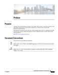
Preface
Preface vii
Document Conventions vii
Related Documentation ix
Obtaining Documentation and Submitting a Service Request ix
CHAPTER 1
Product Overview 1
Switch Models 1
Front Panel 3
PoE and PoE+ Ports 5
10/100/1000 Ports 5
Management Ports 6
USB Type A Port 7
SFP and SFP+ Module Slots 7
LEDs 7
System LED 10
RPS LED 10
IRPS LED 11
Master LED 11
Port LEDs and Modes 11
STACK LED 14
Console LEDs 15
Ethernet Management Port LED 15
Rear Panel 15
FlexStack-Plus Ports and LEDs 17
RPS Connector 18
Cisco RPS 2300 18
AC Power Connector 19
Catalyst 2960-X and 2960-XR Switch Hardware Installation Guide
OL-28309-02
iii
Contents
Power Supply Modules (Applies to the Catalyst 2960-XR Switches) 19
Management Options 20
Network Configurations 21
CHAPTER 2
Switch Installation 23
Safety Warnings 23
Box Contents 26
Tools and Equipment 26
Installation Guidelines 26
Verifying Switch Operation 27
Planning and Installing a Switch Stack (Optional) 28
Stack Guidelines 28
Installing the FlexStack-Plus Module 29
Stack Cabling 31
Stack Bandwidth and Partitioning Examples 32
Power-On Sequence for Switch Stacks 33
Installing the Switch 33
Rack-Mounting 33
Attaching the Rack-Mount Brackets for the Catalyst 2960-X Switches 35
Attaching the Rack-Mount Brackets for the Catalyst 2960-XR Switches 36
Mounting in a Rack 37
Wall-Mounting 38
Attaching the Brackets for Wall-Mounting 38
Attaching the RPS Connector Cover 39
Mounting on a Wall 40
Installing the Switch on a Table or Shelf 41
After Switch Installation 41
Connecting the FlexStack Cables (Optional) 41
Removing a FlexStack Cable 42
Installing the Power Cord Retainer (Optional) 43
Installing SFP and SFP+ Modules 45
Installing an SFP or SFP+ Module 46
Removing an SFP or SFP+ Module 47
Connecting to SFP and SFP+ Modules 47
Connecting to Fiber-Optic SFP and SFP+ Modules 48
Catalyst 2960-X and 2960-XR Switch Hardware Installation Guide
iv
OL-28309-02
Contents
Connecting to 1000BASE-T SFP 49
10/100/1000 PoE+ Port Connections 50
10/100/1000 Port Connections 51
Auto-MDIX Connections 51
Where to Go Next 52
CHAPTER 3
Power Supply Installation 53
Power Supply Module Overview 53
Installation Guidelines 56
Installing or Replacing an AC Power Supply 57
Finding the Serial Number 59
CHAPTER 4
Troubleshooting 61
Diagnosing Problems 61
Switch POST Results 61
Switch LEDs 61
Switch Connections 62
Bad or Damaged Cable 62
Ethernet and Fiber-Optic Cables 62
Link Status 62
10/100/1000 Port Connections 63
10/100/1000 PoE+ Port Connections 63
SFP and SFP+ Module 63
Interface Settings 64
Ping End Device 64
Spanning Tree Loops 64
Switch Performance 64
Speed, Duplex, and Autonegotiation 64
Autonegotiation and Network Interface Cards 64
Cabling Distance 65
Clearing the Switch IP Address and Configuration 65
Finding the Serial Number 66
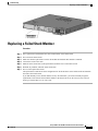
Replacing a Failed Stack Member 67
APPENDIX A
Technical Specifications 69
Catalyst 2960-X and 2960-XR Switch Hardware Installation Guide
OL-28309-02
v
Contents
Environmental Specifications 69
Specifications for the Catalyst 2960-X Switches 70
Specifications for the Catalyst 2960-XR Switches 74
APPENDIX B
Connector and Cable Specifications 77
Connector Specifications 77
10/100/1000 Ports (Including PoE) 77
SFP Module Connectors 78
Cables and Adapters 78
SFP Module Cables 78
Cable Pinouts 80
Console Port Adapter Pinouts 81
APPENDIX C
Configuring the Switch with the CLI-Based Setup Program 83
Accessing the CLI Through Express Setup 83
Accessing the CLI Through the Console Port 83
Connecting the RJ-45 Console Port 84
Connecting the USB Console Port 85
Installing the Cisco Microsoft Windows USB Device Driver 86
Installing the Cisco Microsoft Windows XP USB Driver 86
Installing the Cisco Microsoft Windows 2000 USB Driver 87
Installing the Cisco Microsoft Windows Vista and Windows 7 USB Driver 87
Uninstalling the Cisco Microsoft Windows USB Driver 87
Uninstalling the Cisco Microsoft Windows XP and 2000 USB Driver 87
Using the Setup.exe Program 88
Using the Add or Remove Programs Utility 88
Uninstalling the Cisco Microsoft Windows Vista and Windows 7 USB Driver 88
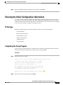
Entering the Initial Configuration Information 89
IP Settings 89
Completing the Setup Program 89
Catalyst 2960-X and 2960-XR Switch Hardware Installation Guide
vi
OL-28309-02
Preface
• Document Conventions, page vii
• Related Documentation, page ix
• Obtaining Documentation and Submitting a Service Request, page ix
Document Conventions
This document uses the following conventions:
Convention
Description
^ or Ctrl
Both the ^ symbol and Ctrl represent the Control (Ctrl) key on a keyboard. For
example, the key combination ^D or Ctrl-D means that you hold down the Control
key while you press the D key. (Keys are indicated in capital letters but are not
case sensitive.)
bold font
Commands and keywords and user-entered text appear in bold font.
Italic font
Document titles, new or emphasized terms, and arguments for which you supply
values are in italic font.
Courier
font
Bold Courier
Terminal sessions and information the system displays appear in courier font.
font
Bold Courier
font indicates text that the user must enter.
[x]
Elements in square brackets are optional.
...
An ellipsis (three consecutive nonbolded periods without spaces) after a syntax
element indicates that the element can be repeated.
|
A vertical line, called a pipe, indicates a choice within a set of keywords or
arguments.
[x | y]
Optional alternative keywords are grouped in brackets and separated by vertical
bars.
Catalyst 2960-X and 2960-XR Switch Hardware Installation Guide
OL-28309-02
vii
Preface
Document Conventions
Convention
Description
{x | y}
Required alternative keywords are grouped in braces and separated by vertical
bars.
[x {y | z}]
Nested set of square brackets or braces indicate optional or required choices
within optional or required elements. Braces and a vertical bar within square
brackets indicate a required choice within an optional element.
string
A nonquoted set of characters. Do not use quotation marks around the string or
the string will include the quotation marks.
<>
Nonprinting characters such as passwords are in angle brackets.
[]
Default responses to system prompts are in square brackets.
!, #
An exclamation point (!) or a pound sign (#) at the beginning of a line of code
indicates a comment line.
Reader Alert Conventions
This document may use the following conventions for reader alerts:
Note
Tip
Caution
Timesaver
Warning
Means reader take note. Notes contain helpful suggestions or references to material not covered in the
manual.
Means the following information will help you solve a problem.
Means reader be careful. In this situation, you might do something that could result in equipment damage
or loss of data.
Means the described action saves time. You can save time by performing the action described in the
paragraph.
Means reader be warned. In this situation, you might perform an action that could result in bodily
injury.
Catalyst 2960-X and 2960-XR Switch Hardware Installation Guide
viii
OL-28309-02
Preface
Related Documentation
Related Documentation
Note
Before installing or upgrading the switch, refer to the release notes.
• Catalyst 2960-X Switch, located at http://www.cisco.com/go/cat2960x_docs.
Catalyst 2960-XR Switch, located at http://www.cisco.com/go/cat2960xr_docs.
• Cisco SFP and SFP+ modules documentation, including compatibility matrixes, located at:
http://www.cisco.com/en/US/products/hw/modules/ps5455/tsd_products_support_series_home.html
Obtaining Documentation and Submitting a Service Request
For information on obtaining documentation, submitting a service request, and gathering additional information,
see the monthly What's New in Cisco Product Documentation, which also lists all new and revised Cisco
technical documentation, at:
http://www.cisco.com/c/en/us/td/docs/general/whatsnew/whatsnew.html
Subscribe to the What's New in Cisco Product Documentation as a Really Simple Syndication (RSS) feed
and set content to be delivered directly to your desktop using a reader application. The RSS feeds are a free
service and Cisco currently supports RSS version 2.0.
Catalyst 2960-X and 2960-XR Switch Hardware Installation Guide
OL-28309-02
ix
Preface
Obtaining Documentation and Submitting a Service Request
Catalyst 2960-X and 2960-XR Switch Hardware Installation Guide
x
OL-28309-02
CHAPTER
1
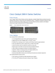
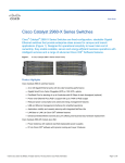
Product Overview
The Catalyst 2960-X and 2960-XR family of switches are Ethernet switches to which you can connect devices
such as Cisco IP Phones, Cisco Wireless Access Points, workstations, and other network devices such as
servers, routers, and other switches.
Some models of the switches support stacking through the Cisco FlexStack-Plus technology. Unless otherwise
noted, the term switch refers to a standalone switch and to a switch stack.
This chapter contains these topics:
• Switch Models, page 1
• Front Panel, page 3
• Rear Panel, page 15
• Management Options, page 20
• Network Configurations, page 21
Switch Models
Table 1: Catalyst 2960-X Switch Models and Descriptions
Switch Model
Supported
Software
Image
Description
Catalyst 2960X-48FPD-L1
LAN Base
48 10/100/1000 Power over Ethernet Plus (PoE+) ports (PoE
budget of 740 W) and 2 small form-factor pluggable (SFP)+2
module slots.
Catalyst 2960X-48LPD-L 1
LAN Base
48 10/100/1000 PoE+ ports (PoE budget of 370 W) and 2
SFP+ module slots.
Catalyst 2960X-24PD-L1
LAN Base
24 10/100/1000 PoE+ ports (PoE budget of 370 W) and 2
SFP+ module slots.
Catalyst 2960-X and 2960-XR Switch Hardware Installation Guide
OL-28309-02
1
Product Overview
Switch Models
Switch Model
Supported
Software
Image
Description
Catalyst 2960X-48TD-L1
LAN Base
48 10/100/1000 ports and 2 SFP+ module slots.
Catalyst 2960X-24TD-L1
LAN Base
24 10/100/1000 ports and 2 SFP+ module slots.
Catalyst 2960X-48FPS-L1
LAN Base
48 10/100/1000 PoE+ ports (PoE budget of 740 W) and 4
SFP3 module slots.
Catalyst 2960X-48LPS-L1
LAN Base
48 10/100/1000 PoE+ ports (PoE budget of 370 W) and 4
SFP module slots.
Catalyst 2960X-24PS-L1
LAN Base
24 10/100/1000 PoE+ ports (PoE budget of 370 W) and 4
SFP module slots.
Catalyst 2960X-48TS-L1
LAN Base
48 10/100/1000 ports and 4 SFP module slots.
Catalyst 2960X-24TS-L1
LAN Base
24 10/100/1000 ports and 4 SFP module slots
Catalyst 2960X-48TS-LL
LAN Lite
48 10/100/1000 ports and 2 SFP module slots.
Catalyst 2960X-24TS-LL
LAN Lite
24 10/100/1000 ports and 2 SFP module slots.
Catalyst 2960X-24PSQ-L
LAN Base
24 10/100/1000 (8 PoE- with PoE budget of 110 W) ports,
fanless, 2 10/100/1000BaseT copper uplinks, and 2 SFP
module slots.
1 Support Cisco FlexStack-Plus technology.
2 SFP+ = 10-Gigabit uplink.
3 SFP = 1-Gigabit uplink.
Table 2: Catalyst 2960-XR Switch Models and Descriptions
Switch Model
Supported
Software
Image
Description
Catalyst 2960XR-48FPD-I1
IP Lite
48 10/100/1000 PoE+ ports (PoE budget of 740 W) 2 SFP+
module slots, 1025-W power supply.
Catalyst 2960XR-48LPD-I1
IP Lite
48 10/100/1000 PoE+ ports (PoE budget of 370 W) 2 SFP+
module slots, 640-W power supply.
Catalyst 2960XR-24PD-I1
IP Lite
24 10/100/1000 PoE+ ports (PoE budget of 370 W) 2 SFP+
module slots, 640-W power supply.
Catalyst 2960XR-48TD-I1
IP Lite
48 10/100/1000 and 2 SFP+ module slots, 250-W power
supply.
Catalyst 2960-X and 2960-XR Switch Hardware Installation Guide
2
OL-28309-02
Product Overview
Front Panel
Switch Model
Supported
Software
Image
Description
Catalyst 2960XR-24TD-I1
IP Lite
24 10/100/1000 and 2 SFP+ module slots, 250-W power
supply.
Catalyst 2960XR-48FPS-I1
IP Lite
48 10/100/1000 PoE+ ports (PoE budget of 740 W) and 4
SFP module slots, 1025-W power supply.
Catalyst 2960XR-48LPS-I1
IP Lite
48 10/100/1000 PoE+ ports (PoE budget of 370 W) and 4
SFP module slots, 640-W power supply.
Catalyst 2960XR-24PS-I1
IP Lite
24 10/100/1000 PoE+ ports (PoE budget of 370 W) and 4
SFP module slots, 640-W power supply.
Catalyst 2960XR-48TS-I1
IP Lite
48 10/100/1000 and 4 SFP module slots, 250-W power supply.
Catalyst 2960XR-24TS-I1
IP Lite
24 10/100/1000 and 4 SFP module slots, 250-W power supply.
Front Panel
This section describes the front panel components:
• 24 or 48 downlink ports of one of these types:
◦10/100/1000
◦10/100/1000 PoE+
• SFP ports
• USB Type A connectors
• USB mini-Type B (console) port
• Ethernet management port
• RJ-45 console port
• LEDs
• Mode button
Catalyst 2960-X and 2960-XR Switch Hardware Installation Guide
OL-28309-02
3
Product Overview
Front Panel
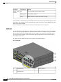
The Catalyst 2960X-48FPD-L switch is shown here as an example. Other switches have similar components.
Figure 1: Catalyst 2960X-48FPD-L Front Panel
1
Mode button and switch LEDs
5
SFP module slots
2
USB mini-Type B (console) port
6
10/100/1000 PoE+ ports
3
USB Type A port
7
RJ-45 console port
4
USB Type A port
8
Ethernet management port
The Catalyst 2960XR-48LPD-I switch is shown here as an example. Other Catalyst 2960-XR switches have
similar components.
Figure 2: Catalyst 2960XR-48LPD-I Front Panel
1
Mode button and switch LEDs
5
SFP+ module slots
Catalyst 2960-X and 2960-XR Switch Hardware Installation Guide
4
OL-28309-02
Product Overview
PoE and PoE+ Ports
2
USB mini-Type B (console) port
6
10/100/1000 PoE+ ports
3
USB Type A port
7
RJ-45 console port
4
USB Type A port
8
Ethernet management port
PoE and PoE+ Ports
The ports provide PoE+ support for devices compliant with IEEE 802.3af, IEEE 802.3at, and ePoE and also
provide Cisco prestandard PoE support for Cisco IP Phones and Cisco Aironet Access Points.
The maximum switch power output is either 740 W or 370 W, depending on the switch model. Intelligent
power management allows flexible power allocation across all ports.
For switches with a 740 W power budget, you can budget the PoE and PoE+:
• 15.4 W of PoE output on 48 ports
• 30 W of PoE+ on 24 ports
For switches with a 370 W power budget, you can budget the PoE and PoE+:
• 15.4 W of PoE output on 24 ports
• 7.7 W of PoE output on 48 ports
• 30 W of PoE+ on 12 ports
• Total power budget can be allocated among the ports
On a per-port basis, you control whether or not a port automatically provides power when an IP phone or an
access point is connected.
The PoE ports use RJ-45 connectors with Ethernet pinouts. The maximum cable length is 328 feet (100 meters).
The 10BASE-T, 100BASE-TX, 1000BASE-T traffic requires Category 5, Category 5e, or Category 6 unshielded
twisted pair (UTP) cable. The 10BASE-T traffic can use Category 3 or Category 4 UTP cable.
Cisco intelligent power management capabilities include enhanced power negotiation, power reservation, and
per-port power policing. For information about configuring and monitoring PoE ports, see the switch software
configuration guide on Cisco.com.
Note
The output of the PoE circuit has been evaluated as a Limited Power Source (LPS) per IEC 60950-1.
10/100/1000 Ports
The 10/100/1000 ports use RJ-45 connectors with Ethernet pinouts. The maximum cable length is 328 feet
(100 meters). The 100BASE-TX traffic requires Category 5, Category 5e, or Category 6 unshielded twisted
pair (UTP) cable. The 10BASE-T traffic can use Category 3 or Category 4 UTP cable.
Catalyst 2960-X and 2960-XR Switch Hardware Installation Guide
OL-28309-02
5
Product Overview
Management Ports
Related Topics
10/100/1000 Port Connections, on page 63
Management Ports
The management ports connect the switch to a PC running Microsoft Windows or to a terminal server.
• Ethernet management port.
• RJ-45 console port (EIA/TIA-232).
• USB mini-Type B console port (5-pin connector).
The 10/100 Ethernet management port connection uses a standard RJ-45 crossover or straight-through cable.
The RJ-45 console port connection uses the supplied RJ-45-to-DB-9 female cable. The USB console port
connection uses a USB Type A to 5-pin mini-Type B cable. The USB console interface speeds are the same
as the RJ-45 console interface speeds.
If you use the USB mini-Type B console port, the Cisco Windows USB device driver must be installed on
any PC connected to the console port (for operation with Microsoft Windows). Mac OS X or Linux do not
require special drivers.
The 4-pin mini-Type B connector resembles the 5-pin mini-Type B connectors. They are not compatible. Use
only the 5-pin mini-Type B.
This illustration shows a 5-pin mini-Type B USB port.
Figure 3: USB Mini-Type B Port
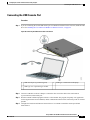
With the Cisco Windows USB device driver, you can connect and disconnect the USB cable from the console
port without affecting Windows HyperTerminal operations.
The console output always goes to both the RJ-45 and the USB console connectors, but the console input is
active on only one of the console connectors at any one time. The USB console takes precedence over the
RJ-45 console. When a cable is connected into the USB console port, the RJ-45 console port becomes inactive.
Conversely, when the USB cable is disconnected from the USB console port, the RJ-45 port becomes active.
You can use the command-line interface (CLI) to configure an inactivity timeout which reactivates the RJ-45
console if the USB console has been activated and no input activity has occurred on the USB console for a
specified time.
After the USB console deactivates due to inactivity, you cannot use the CLI to reactivate it. Disconnect and
reconnect the USB cable to reactivate the USB console. For information on using the CLI to configure the
USB console interface, see the software guide.
Catalyst 2960-X and 2960-XR Switch Hardware Installation Guide
6
OL-28309-02
Product Overview
USB Type A Port
USB Type A Port
The USB Type A port provides access to external USB flash devices (also known as thumb drives or USB
keys).
The port supports Cisco USB flash drives with capacities from 128 MB to 8 GB (USB devices with port
densities of 128 MB, 256 MB, 1 GB, 4 GB, and 8 GB are supported). When combined with stacking, you can
upgrade other switches in the stack from an USB key inserted in any switch within the stack. Cisco IOS
software provides standard file system access to the flash device: read, write, erase, and copy, as well as the
ability to format the flash device with a FAT file system. It provides you with the ability to automatically
upgrade the internal flash with the USB drive’s configuration and image for emergency switch recovery using
USB auto-upgrade. This feature checks the internal flash for a bootable image and configuration and if either
image or the configuration is not available, then the USB drive is checked for boot images and configuration.
If the boot image and configuration are available, these are copied to flash for the reboot.
SFP and SFP+ Module Slots
The switch has either two or four 1-Gigabit SFP or two 10-Gigabit SFP+ module slots. The slots marked
SFP+ support both SFP and SFP+ modules. The SFP slots support only the SFP modules.
For Cisco SFP and SFP+ modules documentation, including compatibility matrixes, refer to this URL: http:/
/www.cisco.com/en/US/products/hw/modules/ps5455/products_device_support_tables_list.html
LEDs
You can use the switch LEDs to monitor switch activity and its performance.
Catalyst 2960-X and 2960-XR Switch Hardware Installation Guide
OL-28309-02
7
Product Overview
LEDs
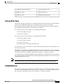
This figure shows the switch LEDs and the Mode button that you use to select a port mode.
Figure 4: Switch LEDs and Mode Button for the Catalyst 2960-X Switch
1
RPS LED4
8
PoE LED5
2
SPEED LED
9
USB mini-Type B console port LED
3
STAT LED
10
USB Type A port
4
SYS LED
11
MGMT LED
5
Mode button
12
CONSOLE LED
6
Master LED6
13
USB Type A port
7
STACK LED
14
Port LEDs
Catalyst 2960-X and 2960-XR Switch Hardware Installation Guide
8
OL-28309-02
Product Overview
LEDs
4 RPS = redundant power system—only on switch models that support RPS.
5 Only on switch models that support PoE.
6 Only on switch models that support stacking.
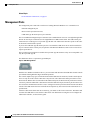
This figure shows the switch LEDs and the Mode button that you use to select a port mode.
Figure 5: Switch LEDs and Mode Button for the Catalyst 2960-XR Switch
1
IRPS LED
8
PoE LED7
2
SPEED LED
9
USB mini-Type B console port LED
3
STAT LED
10
USB Type A port
4
SYS LED
11
MGMT LED
Catalyst 2960-X and 2960-XR Switch Hardware Installation Guide
OL-28309-02
9
Product Overview
LEDs
5
Mode button
12
CONSOLE LED
6
Master LED8
13
USB Type A port
7
STACK LED
14
Port LEDs
7 Only on switch models that support PoE.
8 Only on switch models that support stacking.
System LED
Table 3: System LED
Color
System Status
Off
System is not powered on.
Green
System is operating normally.
Blinking green
POST in progress.
Amber
System is receiving power but is not functioning properly.
Blinking amber
System is sleep mode.
RPS LED
The RPS LED is only available on switch models that have an RPS port . This is available only on the Catalyst
2960-X switches.
Note
RPS is not supported on the Catalyst 2960-X 24PSQ-L switches.
Table 4: RPS LED
Color
RPS Status
Off
RPS is off or not properly connected.
Green
RPS is connected and can provide back-up power.
Blinking green
RPS is connected but is unavailable. It is providing power to another device (redundancy
has been allocated to the other device).
Amber
The RPS is in standby mode or in a fault condition. See the RPS documentation.
Catalyst 2960-X and 2960-XR Switch Hardware Installation Guide
10
OL-28309-02
Product Overview
LEDs
Color
RPS Status
Blinking amber
The power supply in a switch has failed, and the RPS is providing power to the switch
(redundancy has been allocated to this device).
IRPS LED
The IRPS LED is only available on Catalyst 2960-XR switches.
Table 5: IRPS LED
Color
RPS Status
Off
Second power supply is not present.
Green
Both power supplies are present and operating.
Amber
The second power supply is present, but the input is not connected.
Blinking amber
The second power supply is present, but the signal is faulty.
Master LED
This table describes the master LEDs.
Table 6: Master LED
Port Mode
Description
Off
Switch is not the stack master.
Green
Switch is the stack master or a standalone switch.
Amber
An error occurred when the stack was electing the stack master switch, or another type of
stack error occurred.
Port LEDs and Modes
The port and module slots each has a port LED. As a group or individually, the LEDs show information about
the switch and about the ports.
Catalyst 2960-X and 2960-XR Switch Hardware Installation Guide
OL-28309-02
11
Product Overview
LEDs
Table 7: Port Mode LEDs
Mode LED
Port Mode
Description
STAT
Port status
The port status. This is the default mode.
SPEED
Port speed
The port operating speed: 10, 100, 1000 Mb/s, or 10 Gb/s.
STACK
Stack member status
The stack member status.
Stack port status
The stack port status.
PoE port power
The PoE status.
PoE
To select or change a mode, press the Mode button until the desired mode is highlighted. When you change
port modes, the meanings of the port LED colors also change.
Table 8: Meanings of LED Colors in Different Modes
Port Mode
Port LED Color
Meaning
PoE
Off
PoE is off. If the powered device is receiving power from an AC power
source, the port LED is off even if the powered device is connected to
the switch port.
Green
PoE is on. The port LED is green only when the switch port is providing
power.
Alternating
PoE is denied because providing power to the powered device will
green and amber exceed the switch power capacity.
Blinking amber PoE is off due to a fault.
Noncompliant cabling or powered devices can cause a PoE port fault.
Use only standard-compliant cabling to connect Cisco prestandard IP
Phones and wireless access points or IEEE 802.3af-compliant devices.
You must remove any cable or device that causes a PoE fault.
Amber
PoE for the port is disabled. (PoE is enabled by default.)
Catalyst 2960-X and 2960-XR Switch Hardware Installation Guide
12
OL-28309-02
Product Overview
LEDs
Port Mode
Port LED Color
Meaning
STAT (port
status)
Off
No link or port was administratively shut down.
Green
Link present.
Blinking green
Activity. Interface is sending or receiving data.
Alternating
green-amber
Link fault. Error frames can affect connectivity, and errors such as
excessive collisions, cyclic redundancy check (CRC) errors, and
alignment and jabber errors are monitored for a link-fault indication.
Amber
Port is blocked by Spanning Tree Protocol (STP) and is not forwarding
data.
After a port is reconfigured, the port LED can remain amber for up to
30 seconds as STP searches the switch for possible loops.
Blinking amber Port is blocked by STP and is sending and receiving packets.
SPEED
10/100/1000 ports
Off
Port is operating at 10 Mb/s.
Green
Port is operating at 100 Mb/s.
Blinking green
Port is operating at 1000 Mb/s.
SFP module ports
Off
Port is operating at 10 Mb/s.
Green
Port is operating at 100 Mb/s.
Blinking green
Port is operating at 1000 Mb/s.
SFP+ module ports (Applies to the Catalyst 2960X-48FPD-L, 2960X-48LPD-L,
2960X-24PD-L, 2960X-48TD-L, and the 2960X-24TD-L switches.)
SFP+ module ports (Applies to the Catalyst 2960XR-48FPD-I, 2960XR-48LPD-I,
2960XR-24PD-I, 2960XR-48TD-I, and the 2960XR-24TD-I switches.)
Off
Port is not operating.
Blinking green
Port is operating at 10 Gb/s.
Green
Port is operating at 1 Gb/s.
Catalyst 2960-X and 2960-XR Switch Hardware Installation Guide
OL-28309-02
13
Product Overview
LEDs
Port Mode
Port LED Color
Meaning
STACK (stack
member)
Off
No stack member has that member number.
Blinking green
Stack member number.
Green
Member numbers of other stack member switches.
If your switches are stacked and you press the Mode button on any switch, all the switches display the same
selected mode. For example, if you press the Mode button on the stack master to display SPEED, all the other
stack members display SPEED.
Even if PoE mode is not selected, this LED still shows PoE problems if they are detected.
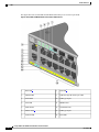
STACK LED
The STACK LED shows the sequence of member switches in a stack. Up to eight switches can be members
of a stack. The first eight port LEDs show the switch member number. For example, if you press the Mode
button and select Stack, the port LED 1 blinks green. The LEDs for port 2 and 3 are solid green, as these
represent the member numbers of other stack members. The other port LEDs are off because there are no
more members in the stack.
This figure shows the LEDs on the first switch, which is stack member number 1.
Figure 6: STACK LED
1
Stack member 1
2
Stack member 2
3
Stack member 3
Catalyst 2960-X and 2960-XR Switch Hardware Installation Guide
14
OL-28309-02
Product Overview
Rear Panel
When you select the STACK LED, the respective STACK LEDs are green when the stack ports (on the switch
rear panel) are up, and the respective Stack LEDs are amber when the ports are down. SFP+ module port
LEDs 1 and 2 on the switch show the status for stack ports 1 and 2, respectively.
If the port LEDs are green on all the switches in the stack, the stack is operating at full bandwidth. If any port
LED is not green, the stack is not operating at full bandwidth.
Console LEDs
The console LEDs show which console port is in use. If you connect a cable to a console port, the switch
automatically uses that port for console communication. If you connect two console cables, the USB console
port has priority.
Table 9: RJ-45 and USB Console LEDs
LED
Color
Description
RJ-45 console port
Green
RJ-45 console port is active.
When this LED is on, the USB console port LED is off.
USB console port
Off
The port is not active, and the USB console port is active.
Green
USB console port is active.
When this LED is on, the RJ-45 console port LED is off.
Off
The port is not active, and the RJ-45 console port is active.
Ethernet Management Port LED
Table 10: Ethernet Management Port LED
Color
Description
Green
Active link to PC.
Off
Inactive link.
Amber
POST failure.
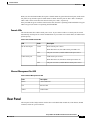
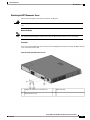
Rear Panel
The rear panel of the Catalyst 2960-X switches have a FlexStack-Plus module slot, a fan exhaust, an RPS
connector, and an AC power connector.
Catalyst 2960-X and 2960-XR Switch Hardware Installation Guide
OL-28309-02
15
Product Overview
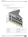
Rear Panel
Note
The FlexStack-Plus module slot is not available on the Catalyst 2960X-48TS-LL and 2960X-24TS-LL
switches. The FlexStack module slot, fan exhaust, and the RPS connector are not available on the Catalyst
2960-X 24PSQ-L switch.
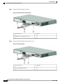
Figure 7: Catalyst 2960-X Switch Rear Panel
1
FlexStack-Plus module slot and cover
3
RPS Connector
2
Fan Exhaust
4
AC power connector
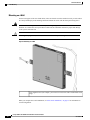
The rear panel of the Catalyst 2960-XR switches have a FlexStack-Plus module slot and power supply module
slots.
Figure 8: Catalyst 2960-XR Switch Rear Panel
Catalyst 2960-X and 2960-XR Switch Hardware Installation Guide
16
OL-28309-02
Product Overview
FlexStack-Plus Ports and LEDs
1
FlexStack-Plus module slot and cover
4
PS OK LED
2
Power supply slot (with blank module)
5
AC power connector on the power supply module
3
AC OK LED
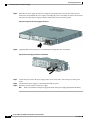
FlexStack-Plus Ports and LEDs
The stacking-capable switch models support stacking with the optional stack kit. It has the FlexStack-Plus
module (hot-swappable) that inserts in the slot located in the switch rear panel, and a 0.5-meter FlexStack
cable to connect the FlexStack-Plus module ports.
Figure 9: FlexStack-Plus Module
1
FlexStack-Plus module
2
LED for Stack port 1
3
LED for Stack port 2
This table lists the FlexStack-Plus module LED colors and their meanings.
Table 11: FlexStack-Plus Module LEDs
Color
Description
Green
Port is active, cable is attached.
Off
The port is not active, no cable is attached.
Table 12: Stack Configurations
Switch
Number of Switches in the Stack
Bandwidth
Stack with Catalyst 2960-X
stack-capable switches
8
80 G
Catalyst 2960-X and 2960-XR Switch Hardware Installation Guide
OL-28309-02
17
Product Overview
RPS Connector
Switch
Number of Switches in the Stack
Bandwidth
Stack with Catalyst 2960-XR
stack-capable switches
8
80 G
Mixed stack with Catalyst 2960-S 4
and Catalyst 2960-X stack-capable
switches
40 G
RPS Connector
The Cisco RPS 2300 (model PWR-RPS2300) supports the Catalyst 2960-X switch.
Note
Warning
RPS is not supported on the Catalyst 2960-X 24PSQ-L switches.
Attach only the following Cisco RPS model to the RPS receptacle: RPS2300. Statement 370
Connect the switch and the redundant power system to different AC power sources.
Use this cable for the RPS: CAB-RPS2300-E.
Cisco RPS 2300
The Cisco RPS 2300 is a redundant power system that can support six external network devices and provide
power to one or two failed devices at a time. It senses when the internal power supply of a connected device
fails and provides power to the failed device, preventing loss of network traffic. For more information, see
the Cisco Redundant Power System 2300 Hardware Installation Guide on Cisco.com at this URL: http://
www.cisco.com/en/US/products/ps7148/prod_installation_guides_list.html
The Cisco RPS 2300 has two output levels: –52 V and 12 V with a total maximum output power of 2300 W.
All supported and connected switches can simultaneously communicate with the RPS 2300. You can configure
these RPS 2300 features through the switch software:
• Enable RPS active or standby mode for each connected switch
• Configure switch priority for RPS support
• List the connected switches and the power-supply module sizes
• Obtain reports when a switch is powered by the RPS
• Obtain status reports for the RPS power-supply module
• Read and monitor backup, failure, and exception history
Catalyst 2960-X and 2960-XR Switch Hardware Installation Guide
18
OL-28309-02
Product Overview
AC Power Connector
AC Power Connector
Note
This applies to the Catalyst 2960-X switches.
The switch is powered through the internal power supply. The internal power supply is an autoranging unit
that supports input voltages between 100 and 240 VAC. Use the supplied AC power cord to plug it into an
AC power outlet.
Power Supply Modules (Applies to the Catalyst 2960-XR Switches)
The switch operates with either one or two active power supply modules. You can use two AC modules, or
one module and a blank cover.
Note
The Catalyst 2960XR-48FPD-I and 2960XR-48FPS-I only support the PWR-C2-1025WAC power supply.
You cannot use the PWR-C2-250WAC and PWR-C2-640WAC power supplies in these switches.
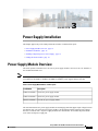
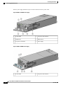
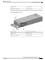
Table 13: Power Supply Model Numbers and Description
Part Number
Description
PWR-C2-250WAC= 250-W AC power supply module.
PWR-C2-640WAC= 640-W AC power supply module.
PWR-C2-1025WAC= 1025-W AC power supply module.
The 250-W and 640-W AC power supply modules are autoranging units that support input voltages between
100 and 240 VAC. The 1025-W power supply module is an autoranging unit that supports input voltages
between 115 and 240 VAC. All power supply modules have internal fans. All switches ship with a blank
cover in the second power supply slot.
Table 14: Available PoE with Different Combinations of Power Supplies
Primary Power
Supply
Secondary Power
Supply
Available Power for Switch Power
PoE+
Redundancy
Available PoE
Power when One PS
Fails
0
No
—
PWR-C2-250WAC= PWR-C2-250WAC= 0
Yes
—
PWR-C2-640WAC= —
370 W
No
—
PWR-C2-640WAC= PWR-C2-640WAC= 370 W
Yes
370 W
PWR-C2-250WAC= —
Catalyst 2960-X and 2960-XR Switch Hardware Installation Guide
OL-28309-02
19
Product Overview
Management Options
Primary Power
Supply
Secondary Power
Supply
Available Power for Switch Power
PoE+
Redundancy
Available PoE
Power when One PS
Fails
740 W
No
—
PWR-C2-1025WAC= PWR-C2-1025WAC= 740 W
Yes
740 W
PWR-C2-1025WAC= —
Management Options
• Cisco Network Assistant
Cisco Network Assistant is a PC-based network management GUI application for LANs of small and
medium-sized businesses. You can use the GUI to configure and manage switch clusters or standalone
switches. Cisco Network Assistant is available at no cost and can be downloaded from this URL: http:/
/www.cisco.com/en/US/products/ps5931/index.html
For information on starting the Network Assistant application, see the Getting Started with Cisco Network
Assistant guide on Cisco.com.
• Device Manager
You can use Device Manager in the switch memory to manage individual and standalone switches. This
web interface provides configuration and monitoring from anywhere in your network. For information,
see the switch getting started guide and the Device Manager online help.
• Cisco IOS CLI
You can configure and monitor the switch and switch cluster members from the CLI. Access the CLI
by connecting your management station to the switch console port or by using Telnet from a remote
management station. See the switch command reference on Cisco.com for information.
• Cisco Prime Infrastructure
Cisco Prime Infrastructure combines the wireless functionality of Cisco Prime Network Control System
(NCS) and the wired functionality of Cisco Prime LAN Management Solution (LMS), with application
performance monitoring and troubleshooting capabilities of Cisco Prime Assurance Manager. For more
information, see the Cisco Prime Infrastructure documentation on Cisco.com.
• Catalyst Smart Operations
The Smart Install feature provides a single point of management (director) in a network. You can use it
to provide a zero touch image and configuration upgrade of newly deployed switches and image and
configuration downloads for any client switches. For information, see the Cisco Smart Install
Configuration Guide on Cisco.com.
Auto Smartports macros dynamically configure ports based on the device type detected on the port.
When the switch detects a new device, it applies the appropriate Auto Smartports macro on the port.
For information about configuring Auto Smartports, see the switch software configuration guide on
Cisco.com.
Catalyst 2960-X and 2960-XR Switch Hardware Installation Guide
20
OL-28309-02
Product Overview
Network Configurations
Network Configurations
See the switch software configuration guide on Cisco.com for network configuration concepts and examples
of using the switch to create dedicated network segments and interconnecting the segments through Fast
Ethernet and Gigabit Ethernet connections.
Catalyst 2960-X and 2960-XR Switch Hardware Installation Guide
OL-28309-02
21
Product Overview
Network Configurations
Catalyst 2960-X and 2960-XR Switch Hardware Installation Guide
22
OL-28309-02
CHAPTER
2
Switch Installation
For initial switch setup, assigning the switch IP address, and powering on information, see the switch getting
started guide on Cisco.com.
This chapter contains these topics:
• Safety Warnings, page 23
• Box Contents, page 26
• Tools and Equipment, page 26
• Installation Guidelines, page 26
• Verifying Switch Operation, page 27
• Planning and Installing a Switch Stack (Optional), page 28
• Installing the Switch, page 33
• Connecting the FlexStack Cables (Optional), page 41
• Installing the Power Cord Retainer (Optional), page 43
• Installing SFP and SFP+ Modules, page 45
• Connecting to SFP and SFP+ Modules, page 47
• 10/100/1000 PoE+ Port Connections, page 50
• 10/100/1000 Port Connections, page 51
• Where to Go Next, page 52
Safety Warnings
This section includes the basic installation caution and warning statements. Read this section before you start
the installation procedure. Translations of the warning statements appear in the RCSI guide on Cisco.com.
Catalyst 2960-X and 2960-XR Switch Hardware Installation Guide
OL-28309-02
23
Switch Installation
Safety Warnings
Warning
Before working on equipment that is connected to power lines, remove jewelry (including rings, necklaces,
and watches). Metal objects will heat up when connected to power and ground and can cause serious burns
or weld the metal object to the terminals. Statement 43
Warning
Do not stack the chassis on any other equipment. If the chassis falls, it can cause severe bodily injury and
equipment damage. Statement 48
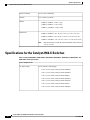
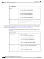
Warning
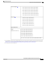
This product must be connected to a power-over-ethernet (PoE) IEEE 802.3af compliant power source or
an IEC60950 compliant limited power source. Statement 353
Warning
Read the wall-mounting instructions carefully before beginning installation. Failure to use the correct
hardware or to follow the correct procedures could result in a hazardous situation to people and damage
to the system. Statement 378
Warning
If a Cisco external power system is not connected to the switch, install the provided connector cover on
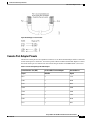
the back of the switch. Statement 386
Warning
Attach only the following Cisco external power system to the switch: PWR-RPS2300 Statement 387
Warning
Do not work on the system or connect or disconnect cables during periods of lightning activity. Statement
1001
Warning
Read the installation instructions before connecting the system to the power source. Statement 1004
Warning
To prevent bodily injury when mounting or servicing this unit in a rack, you must take special precautions
to ensure that the system remains stable. The following guidelines are provided to ensure your safety:
• This unit should be mounted at the bottom of the rack if it is the only unit in the rack.
• When mounting this unit in a partially filled rack, load the rack from the bottom to the top with the
heaviest component at the bottom of the rack.
• If the rack is provided with stabilizing devices, install the stabilizers before mounting or servicing
the unit in the rack.
Statement 1006
Catalyst 2960-X and 2960-XR Switch Hardware Installation Guide
24
OL-28309-02
Switch Installation
Safety Warnings
Warning
Class 1 laser product. Statement 1008
Warning
This unit is intended for installation in restricted access areas. A restricted access area can be accessed
only through the use of a special tool, lock and key, or other means of security. Statement 1017
Warning
The plug-socket combination must be accessible at all times, because it serves as the main disconnecting
device. Statement 1019
Warning
This equipment must be grounded. Never defeat the ground conductor or operate the equipment in the
absence of a suitably installed ground conductor. Contact the appropriate electrical inspection authority
or an electrician if you are uncertain that suitable grounding is available. Statement 1024
Warning
This unit might have more than one power supply connection. All connections must be removed to
de-energize the unit. Statement 1028
Warning
Only trained and qualified personnel should be allowed to install, replace, or service this equipment.
Statement 1030
Warning
Ultimate disposal of this product should be handled according to all national laws and regulations. Statement
1040
Warning
For connections outside the building where the equipment is installed, the following ports must be connected
through an approved network termination unit with integral circuit protection: 10/100/1000 Ethernet.
Statement 1044
Warning
When installing or replacing the unit, the ground connection must always be made first and disconnected
last. Statement 1046
Warning
To prevent the system from overheating, do not operate it in an area that exceeds the maximum
recommended ambient temperature of: <113°F (45°C). Statement 1047
Catalyst 2960-X and 2960-XR Switch Hardware Installation Guide
OL-28309-02
25
Switch Installation
Box Contents
Warning
This warning symbol means danger. You are in a situation that could cause bodily injury. Before you
work on any equipment, be aware of the hazards involved with electrical circuitry and be familiar with
standard practices for preventing accidents. Use the statement number provided at the end of each warning
to locate its translation in the translated safety warnings that accompanied this device. Statement 1071
Warning
Voltages that present a shock hazard may exist on Power over Ethernet (PoE) circuits if interconnections
are made using uninsulated exposed metal contacts, conductors, or terminals. Avoid using such
interconnection methods, unless the exposed metal parts are located within a restricted access location
and users and service people who are authorized within the restricted access location are made aware of
the hazard. A restricted access area can be accessed only through the use of a special tool, lock and key
or other means of security. Statement 1072
Warning
No user-serviceable parts inside. Do not open. Statement 1073
Warning
Installation of the equipment must comply with local and national electrical codes. Statement 1074
Warning
To prevent airflow restriction, allow clearance around the ventilation openings to be at least: 3 inches (7.6
cm). Statement 1076
Warning
Hot surface. Statement 1079
Applies to the Catalyst 2960X-24PSQ-L switches.
Box Contents
The switch getting started guide describes the box contents. If any item is missing or damaged, contact your
Cisco representative or reseller for support.
Tools and Equipment
Obtain these necessary tools and equipment:
• A number-2 Phillips screwdriver to rack-mount the switch.
Installation Guidelines
When determining where to install the switch, verify that these guidelines are met:
Catalyst 2960-X and 2960-XR Switch Hardware Installation Guide
26
OL-28309-02
Switch Installation
Verifying Switch Operation
• Clearance to the switch front and rear panel meets these conditions:
◦Front-panel LEDs can be easily read.
◦Access to ports is sufficient for unrestricted cabling.
◦AC power cord can reach from the AC power outlet to the connector on the switch rear panel.
◦Access to the rear of the rack is sufficient for connecting FlexStack cables to stacked switches, or
connecting the optional Cisco Redundant Power Supply (RPS) 2300.
• Cabling is away from sources of electrical noise, such as radios, power lines, and fluorescent lighting
fixtures. Make sure that the cabling is safely away from other devices that might damage the cables.
• For switches with the optional 1025-W power-supply module, first rack-mount the switch before installing
the power-supply module.
• Make sure power-supply modules are securely inserted in the chassis before moving the switch.
• When connecting or disconnecting the power cord on a switch that is installed above or below a 1025-W
power supply-equipped switch, you might need to remove the module from the switch to access the
power cord.
• Airflow around the switch and through the vents is unrestricted.
• For the Catalyst 2960X-24PSQ-L switches: Allow these clearances:
• Top and bottom: 1.75 in. (44.44 mm)
• Back of switch: 3 in. (76.19 mm)
• Temperature around the unit does not exceed 113°F (45°C). If the switch is installed in a closed or
multirack assembly, the temperature around it might be greater than normal room temperature.
• Humidity around the switch does not exceed 95 percent.
• Altitude at the installation site is not greater than 10,000 feet.
• For 10/100/1000 fixed ports, the cable length from a switch to a connected device cannot exceed 328
feet (100 meters).
• Cooling mechanisms, such as fans and blowers in the switch, can draw dust and other particles causing
contaminant buildup inside the chassis, which can result in system malfunction. You must install this
equipment in an environment as free from dust and foreign conductive material (such as metal flakes
from construction activities) as is possible.
Verifying Switch Operation
Before you install the switch in a rack, on a wall, or on a table or shelf, power on the switch and verify that
it passes POST.
To power on the switch, plug one end of the AC power cord into the switch AC power connector, and plug
the other end into an AC power outlet.
As the switch powers on, it begins the POST, a series of tests that runs automatically to ensure that the switch
functions properly. LEDs can blink during the test. POST lasts approximately 1 minute. When the switch
Catalyst 2960-X and 2960-XR Switch Hardware Installation Guide
OL-28309-02
27
Switch Installation
Planning and Installing a Switch Stack (Optional)
begins POST, the SYST, RPS, STAT, and SPEED LEDs turn green. The SYST LED blinks green, and the
other LEDs remain solid green.
When the switch completes POST successfully, the SYST LED remains green. The RPS LED remains green
for some time and then reflects the switch operating status. The other LEDs turn off and then reflect the switch
operating status. If a switch fails POST, the SYST LED turns amber.
POST failures are usually fatal. Call Cisco technical support representative if your switch fails POST.
After a successful POST, unplug the power cord from the switch and install the switch in a rack, on a wall,
on a table, or on a shelf.
If your configuration has an RPS, connect the switch and the RPS to different AC power sources. See the
Cisco RPS documentation for information.
Note
Warning
When you connect the RPS to the switch, put the RPS in standby mode. Set the RPS to active mode during
normal operation.
Attach only the following Cisco external power system to the switch: PWR-RPS2300 Statement 387
Planning and Installing a Switch Stack (Optional)
Note
This section applies only to the Catalyst 2960-X and 2960-XR stacking-capable switches.
Stack Guidelines
• Connect only Catalyst 2960-X or 2960-S switches in a mixed switch stack.
Note
You can only create mixed stacks with Catalyst 2960-X or 2960-S switches (up to four
switches). You cannot create mixed stacks with other switches. Catalyst 2960-XR
switches cannot be added to mixed stacks. They can only stack with other Catalyst
2960-XR switches.
• Install the FlexStack-Plus module and the FlexStack cable.
Note
The FlexStack-Plus module is hot-swappable and can be inserted while the switch is
powered on.
• Order the appropriate cable from your Cisco sales representative. The length of FlexStack cable depends
on your configuration. These are the different sizes available:
Catalyst 2960-X and 2960-XR Switch Hardware Installation Guide
28
OL-28309-02
Switch Installation
Installing the FlexStack-Plus Module
◦CAB-STK-E-0.5M= (0.5-meter cable)
◦CAB-STK-E-1M= (1-meter cable)
◦CAB-STK-E-3M= (3-meter cable)
• Make sure that you have access to the switch rear panel and to the rear of the rack.
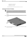
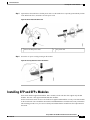
Installing the FlexStack-Plus Module
Note
The switch should always have a blank module installed when a FlexStack-Plus module is not used.
The Catalyst 2960X-48P-L switch is shown as an example. You can install the module in other switches as
shown.
Procedure
Step 1
Use a number 2 Phillips-head screwdriver to remove the FlexStack-Plus module blank cover on the switch
back panel.
Step 2
Grasp the FlexStack-Plus module on the sides, and insert it into the module slot. Push the module in completely
until you feel it snap into place.
Catalyst 2960-X and 2960-XR Switch Hardware Installation Guide
OL-28309-02
29
Switch Installation
Installing the FlexStack-Plus Module
Step 3
Secure the screws on each side of the module.
Note
Avoid overtightening the
screws.
Catalyst 2960-X and 2960-XR Switch Hardware Installation Guide
30
OL-28309-02
Switch Installation
Stack Cabling
Stack Cabling
These figures show the switches stacked in a vertical rack or on a table. The connections are redundant. A
Catalyst 2960-X switch is shown in the examples, the Catalyst 2960-XR switch can be stacked in the same
way.
Figure 10: Stacking Switches with the 0.5-meter FlexStack Cable
Figure 11: Stacking Switches with 0.5-meter and 3-meter FlexStack Cables
Catalyst 2960-X and 2960-XR Switch Hardware Installation Guide
OL-28309-02
31
Switch Installation
Stack Bandwidth and Partitioning Examples
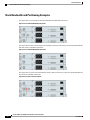
Stack Bandwidth and Partitioning Examples
This figure shows a stack that provides full bandwidth with redundant connections.
Figure 12: Stack with Full Bandwidth Connections
This figure shows a stack with incomplete stack cabling connections. This stack provides only half bandwidth
and does not have redundant connections.
Figure 13: Stack with Half Bandwidth Connections
This figure shows a stack with a bad FlexStack cable in link B. This stack provides only half bandwidth and
does not have redundant connections.
Figure 14: Stack with a Failover Condition
Catalyst 2960-X and 2960-XR Switch Hardware Installation Guide
32
OL-28309-02
Switch Installation
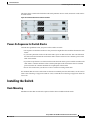
Power-On Sequence for Switch Stacks
This figure shows a stack with a bad link B. This stack partitions into two stacks, and switch 1 and switch 3
are stack masters.
Figure 15: Partitioned Stack with a Failover Condition
Power-On Sequence for Switch Stacks
Consider these guidelines before you power on the switches in a stack:
• The sequence in which the switches are first powered on might affect the switch that becomes the stack
master.
• If you want a particular switch to be the stack master, power on that switch first. This switch becomes
the stack master and remains the stack master until a master reelection. After 2 minutes, power on the
other stack switches.
• If you have no preference as to which switch becomes the stack master, power on all the switches in the
stack within a 1-minute timeframe. These switches participate in the stack master election. Switches
powered on after the 1-minute timeframe do not participate in the election.
• Power off a switch before you add it to or remove it from an existing switch stack.
For conditions that can cause a stack master reelection or to manually elect the stack master, see the Catalyst
2960-X Switch Stacking Configuration Guide or Catalyst 2960-XR Switch Stacking Configuration Guide on
Cisco.com.
Installing the Switch
Rack-Mounting
Installation in other than 19-inch racks requires a bracket kit not included with the switch.
Catalyst 2960-X and 2960-XR Switch Hardware Installation Guide
OL-28309-02
33
Switch Installation
Rack-Mounting
Warning
To prevent bodily injury when mounting or servicing this unit in a rack, you must take special precautions
to ensure that the system remains stable. The following guidelines are provided to ensure your safety:
• This unit should be mounted at the bottom of the rack if it is the only unit in the rack.
• When mounting this unit in a partially filled rack, load the rack from the bottom to the top with the
heaviest component at the bottom of the rack.
• If the rack is provided with stabilizing devices, install the stabilizers before mounting or servicing
the unit in the rack.
Statement 1006
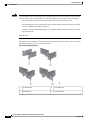
This figure shows the standard 19-inch brackets and other optional mounting brackets. You can order the
optional brackets from your Cisco sales representative.
Figure 16: Rack-Mounting Brackets
1
19-inch brackets
3
23-inch brackets
2
ETSI brackets
4
24-inch brackets
Catalyst 2960-X and 2960-XR Switch Hardware Installation Guide
34
OL-28309-02
Switch Installation
Rack-Mounting
Attaching the Rack-Mount Brackets for the Catalyst 2960-X Switches
Procedure
Use two Phillips flat-head screws to attach the long side of the bracket to each side of the switch.
Figure 17: Attaching Brackets for 19-inch Racks
1
Front-mounting position
3
Mid-mounting position
2
Number-8 Phillips flat-head screws (48-2927-01) 4
Rear-mounting position
Catalyst 2960-X and 2960-XR Switch Hardware Installation Guide
OL-28309-02
35
Switch Installation
Rack-Mounting
Attaching the Rack-Mount Brackets for the Catalyst 2960-XR Switches
Procedure
Use four Phillips flat-head screws to attach the long side of the bracket to each side of the switch.
Figure 18: Attaching Brackets for 19-inch Racks
1
Front-mounting position
3
Mid-mounting position
2
Number-8 Phillips flat-head screws (48-2927-01) 4
Rear-mounting position
Catalyst 2960-X and 2960-XR Switch Hardware Installation Guide
36
OL-28309-02
Switch Installation
Rack-Mounting
Mounting in a Rack
Procedure
Step 1
Step 2
Use the four supplied Phillips machine screws to attach the brackets to the rack.
Use the black Phillips machine screw to attach the cable guide to the left or right bracket.
1
Cable guide
4
Number-12 Phillips pan-head screws
(48-0523-01) or Number-10 Phillips pan-head
screws (48-0627-01)
2
Phillips machine screw, black (48-0654-01)
5
Mid-mounting position
Catalyst 2960-X and 2960-XR Switch Hardware Installation Guide
OL-28309-02
37
Switch Installation
Wall-Mounting
3
Front-mounting position
6
Rear-mounting position
Wall-Mounting
Warning
Read the wall-mounting instructions carefully before beginning installation. Failure to use the correct
hardware or to follow the correct procedures could result in a hazardous situation to people and damage
to the system. Statement 378
Attaching the Brackets for Wall-Mounting
Procedure
Step 1
Step 2
Attach a 19-inch bracket to one side of the switch.
Follow the same steps to attach the second bracket to the opposite side.
Figure 19: Attaching the 19-inch Brackets for Wall-Mounting
1
Number-8 phillips flat-head screws (48-2927-01)
Catalyst 2960-X and 2960-XR Switch Hardware Installation Guide
38
OL-28309-02
Switch Installation
Wall-Mounting
Attaching the RPS Connector Cover
This section only applies to the switches that have an RPS port.
Warning
If an RPS is not connected to the switch, install an RPS connector cover on the back of the switch. Statement
265
Before You Begin
Note
The Catalyst 2960X-24PSQ-L switches do not have an RPS connector and a cover is not needed.
Procedure
If you are not using an RPS with your switch, use the two Phillips pan-head screws to attach the RPS connector
cover to the back of the switch.
Figure 20: Attaching the RPS Connector Cover
1
Phillips pan-head screws (48-0482-01)
2
RPS connector cover
3
RPS connector
Catalyst 2960-X and 2960-XR Switch Hardware Installation Guide
OL-28309-02
39
Switch Installation
Wall-Mounting
Mounting on a Wall
For the best support of the switch and cables, make sure that the switch is attached securely to wall studs or
to a firmly attached plywood-mounting backboard. Mount the switch with the front panel facing down.
Warning
Read the wall-mounting instructions carefully before beginning installation. Failure to use the correct
hardware or to follow the correct procedures could result in a hazardous situation to people and damage
to the system. Statement 378
Caution
Following safety regulations, wall-mount the switch with its front panel facing down.
Figure 21: Mounting on a Wall
1
User-supplied screws (for example, you can use # 6 wood screws with a washer head 1-inch
long).
When you complete the switch installation, see After Switch Installation, on page 41 for information on
switch configuration.
Catalyst 2960-X and 2960-XR Switch Hardware Installation Guide
40
OL-28309-02
Switch Installation
Installing the Switch on a Table or Shelf
Installing the Switch on a Table or Shelf
Procedure
Step 1
Step 2
Step 3
Step 4
To install the switch on a table or shelf, locate the adhesive strip with the rubber feet in the mounting-kit
envelope.
Attach the four rubber feet to the four circular etches on the bottom of the chassis.
Place the switch on the table or shelf near an AC power source.
When you complete the switch installation, see After Switch Installation, on page 41 for information on
switch configuration.
After Switch Installation
• Configure the switch by running Express Setup to enter the initial switch configuration. See the switch
getting started guide on Cisco.com.
• Use the CLI setup program to enter the initial switch configuration.
• Connect to the stack ports.
• Install the power cord retainer (optional).
• Connect to the front-panel ports.
Related Topics
Connecting the FlexStack Cables (Optional), on page 41
Installing the Power Cord Retainer (Optional), on page 43
Installing an SFP or SFP+ Module, on page 46
10/100/1000 PoE+ Port Connections, on page 50
Connecting the FlexStack Cables (Optional)
Always use a Cisco-approved FlexStack cable to connect the switches.
Note
Caution
This is only supported on the stack-capable switches.
Use only approved cables, and connect only to other Catalyst 2960-X or 2960-S switches. Equipment
might be damaged if connected to other nonapproved Cisco cables or equipment.
Catalyst 2960-X and 2960-XR Switch Hardware Installation Guide
OL-28309-02
41
Switch Installation
Removing a FlexStack Cable
Procedure
Step 1
Step 2
Remove the dust covers from the FlexStack cables, and store them for future use.
Insert one end of the FlexStack cable into the stack port of the first switch. Insert the other end of the cable
into the stack port on the other switch. Make sure that you insert the cables in completely until you feel them
snap into place.
When you connect the FlexStack cable to the STACK 1 port, the tab should be above the connector.
When you connect the FlexStack cable to the STACK 2 port, the tab should be below the connector.
Replace the dust covers when you remove the FlexStack cables from the connectors.
Note
Step 3
Caution
Removing and installing the FlexStack cable can shorten its useful life. Do not remove and insert
the cable more often than is absolutely necessary.
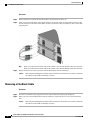
Removing a FlexStack Cable
Procedure
Step 1
Step 2
To remove a FlexStack cable, grasp the tab on the cable connector and gently pull straight out.
When you remove the FlexStack cables from the connectors, replace the dust covers to protect them from
dust.
Caution
Removing and installing the FlexStack cable can shorten its useful life. Do not remove and insert
the cable more often than is absolutely necessary.
Catalyst 2960-X and 2960-XR Switch Hardware Installation Guide
42
OL-28309-02
Switch Installation
Installing the Power Cord Retainer (Optional)
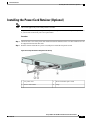
Installing the Power Cord Retainer (Optional)
Note
This section applies only to the Catalyst 2960-X switches.
The power cord retainer is optional (part number [PWR-CLP=]). You can order it when you order your switch,
or you can order it later from your Cisco representative.
Procedure
Step 1
Step 2
Choose the sleeve size of the power cord retainer based on the thickness of the cord. The smaller sleeve can
be snapped off and used for thin cords.
Slide the retainer around the AC power cord, and pass it around the loop on the switch.
Figure 22: Inserting the Retainer Through the Lanced Loop
1
AC power cord
3
Sleeve for thinner power cords
2
Power cord retainer
4
Loop
Catalyst 2960-X and 2960-XR Switch Hardware Installation Guide
OL-28309-02
43
Switch Installation
Installing the Power Cord Retainer (Optional)
Step 3
Slide the retainer through the first latch.
Figure 23: Sliding the Retainer Through the Latch
Step 4
1
AC power cord
2
Smaller sleeve for thin power cords
3
Latch
3
Latches
Slide the retainer through the other latches to lock it.
Figure 24: Locking the Retainer
1
AC power cord
2
Sleeve for thin power cords
Catalyst 2960-X and 2960-XR Switch Hardware Installation Guide
44
OL-28309-02
Switch Installation
Installing SFP and SFP+ Modules
Step 5
(Optional) Use the small sleeve for thin power cords. Use the small sleeve to provide greater stability for thin
cords. Detach the sleeve, and slide it over the power cord.
Figure 25: Sleeve Around the Power Cord
1
Step 6
Sleeve for thin power cords
2
AC power cord
Secure the AC power cord by pressing on the retainer.
Figure 26: Securing the Power Cord in the Retainer
Installing SFP and SFP+ Modules
Some switch models support SFP modules, SFP+ modules, or both. The SFP slots support only the SFP
modules. The SFP+ slots support both SFP and SFP+ modules.
See the switch release notes on Cisco.com for the list of supported SFP modules. Use only Cisco SFP modules
on the switch. Each Cisco module has an internal serial EEPROM that is encoded with security information.
This encoding provides a way for Cisco to identify and validate that the module meets the requirements for
the switch.
Catalyst 2960-X and 2960-XR Switch Hardware Installation Guide
OL-28309-02
45
Switch Installation
Installing an SFP or SFP+ Module
For information about installing, removing, cabling, and troubleshooting SFP modules, see the module
documentation that shipped with your device.
Related Topics
SFP and SFP+ Module Slots, on page 7
Installing an SFP or SFP+ Module
Before You Begin
When installing SFP or SFP+ modules, observe these guidelines:
• Do not remove the dust plugs from the modules or the rubber caps from the fiber-optic cable until you
are ready to connect the cable. The plugs and caps protect the module ports and cables from contamination
and ambient light.
• To prevent ESD damage, follow your normal board and component handling procedures when connecting
cables to the switch and other devices.
Caution
Removing and installing an SFP or SFP+ module can shorten its useful life. Do not
remove and insert any module more often than is absolutely necessary.
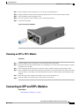
Procedure
Step 1
Step 2
Attach an ESD-preventive wrist strap to your wrist and to a bare metal surface.
Find the send (TX) and receive (RX) markings on the module top.
On some SFP or SFP+ modules, the send and receive (TX and RX) markings might be replaced by arrows
that show the direction of the connection.
Catalyst 2960-X and 2960-XR Switch Hardware Installation Guide
46
OL-28309-02
Switch Installation
Removing an SFP or SFP+ Module
Step 3
Step 4
Step 5
Step 6
Step 7
If the module has a bale-clasp latch, move it to the open, unlocked position.
Align the module in front of the slot opening, and push until you feel the connector snap into place.
If the module has a bale-clasp latch, close it.
For fiber-optic SFP or SFP+ modules, remove the dust plugs and save.
Connect the SFP cables.
Figure 27: Installing an SFP Module
Removing an SFP or SFP+ Module
Procedure
Step 1
Step 2
Step 3
Step 4
Step 5
Step 6
Attach an ESD-preventive wrist strap to your wrist and to a bare metal surface.
Disconnect the cable from the SFP module. For reattachment, note which cable connector plug is send (TX)
and which is receive (RX).
Insert a dust plug into the optical ports of the SFP or SFP+ module to keep the optical interfaces clean.
If the module has a bale-clasp latch, pull the bale out and down to eject the module. If the latch is obstructed
and you cannot use your finger, use a small, flat-blade screwdriver or other long, narrow instrument to open
the latch.
Grasp the SFP or SFP+ module, and carefully remove it from the module slot.
Place the module in an antistatic bag or other protective environment.
Connecting to SFP and SFP+ Modules
Related Topics
SFP and SFP+ Module Slots, on page 7
Catalyst 2960-X and 2960-XR Switch Hardware Installation Guide
OL-28309-02
47
Switch Installation
Connecting to Fiber-Optic SFP and SFP+ Modules
Connecting to Fiber-Optic SFP and SFP+ Modules
Warning
Class 1 laser product. Statement 1008
Caution
Do not remove the rubber plugs from the SFP or SFP+ module port or the rubber caps from the fiber-optic
cable until you are ready to connect the cable. The plugs and caps protect the SFP module ports and cables
from contamination and ambient light. Before connecting to the SFP module, be sure that you understand
the port and cabling stipulations.
Procedure
Step 1
Step 2
Step 3
Remove the rubber plugs from the module port and fiber-optic cable, and store them for future use.
Insert one end of the fiber-optic cable into the SFP or SFP+ module port.
Insert the other cable end into a fiber-optic receptacle on a target device.
Figure 28: Connecting to a Fiber-Optic SFP Module Port
Step 4
Observe the port status LED.
The LED turns green when the switch and the target device have an established link.
The LED turns amber while the STP discovers the network topology and searches for loops. This process
takes about 30 seconds, and then the port LED turns green.
If the LED is off, the target device might not be turned on, there might be a cable problem, or there might be
problem with the adapter installed in the target device.
Catalyst 2960-X and 2960-XR Switch Hardware Installation Guide
48
OL-28309-02
Switch Installation
Connecting to 1000BASE-T SFP
Related Topics
SFP Module Connectors, on page 78
Connecting to 1000BASE-T SFP
When connecting to a 1000BASE-T device, be sure to use a four twisted-pair, Category 5 or higher cable.
Note
Caution
The automatic medium-dependent interface crossover (auto-MDIX) feature is enabled by default. For
configuration information for this feature, see the switch software configuration guide or the switch
command reference on Cisco.com.
To prevent ESD damage, follow your normal board and component handling procedures.
Procedure
Step 1
Step 2
Connect one end of the cable to the SFP module port. Insert a four twisted-pair, straight-through cable when
you connect to servers, workstations, and routers. Insert a four twisted-pair, crossover cable when you connect
to switches or repeaters.
Connect the other end of the cable to an RJ-45 connector on the other device.
Figure 29: Connecting to a 1000BASE-T SFP Module
Catalyst 2960-X and 2960-XR Switch Hardware Installation Guide
OL-28309-02
49
Switch Installation
10/100/1000 PoE+ Port Connections
1
Step 3
RJ-45 connector
Observe the port status LED.
• The LED turns green when the switch and the other device have an established link.
• The LED turns amber while the STP discovers the network topology and searches for loops. This process
takes about 30 seconds, and then the port LED turns green.
• If the LED is off, the other device might not be turned on, there might be a cable problem, or there might
be a problem with the adapter in the other device.
Step 4
If necessary, reconfigure and restart the switch or other device.
10/100/1000 PoE+ Port Connections
The ports provide PoE support for devices compliant with IEEE 802.3af and 802.3at (PoE+), and also provide
Cisco prestandard PoE support for Cisco IP Phones and Cisco Aironet Access Points.
On a per-port basis, you can control whether or not a port automatically provides power when an IP phone
or an access point is connected.
To access an advanced PoE planning tool, use the Cisco Power Calculator available on Cisco.com at this
URL: http://tools.cisco.com/cpc/launch.jsp
You can use this application to calculate the power supply requirements for a specific PoE configuration. The
results show output current, output power, and system heat dissipation.
Warning
Voltages that present a shock hazard may exist on Power over Ethernet (PoE) circuits if interconnections
are made using uninsulated exposed metal contacts, conductors, or terminals. Avoid using such
interconnection methods, unless the exposed metal parts are located within a restricted access location
and users and service people who are authorized within the restricted access location are made aware of
the hazard. A restricted access area can be accessed only through the use of a special tool, lock and key
or other means of security. Statement 1072
Caution
Category 5e and Category 6 cables can store high levels of static electricity. Always ground the cables to
a suitable and safe earth ground before connecting them to the switch or other devices.
Caution
Noncompliant cabling or powered devices can cause a PoE port fault. Use only standard-compliant cabling
to connect Cisco prestandard IP Phones and wireless access points, IEEE 802.3af, or 802.3at
(PoE+)-compliant devices. You must remove any cable or device that causes a PoE fault.
Catalyst 2960-X and 2960-XR Switch Hardware Installation Guide
50
OL-28309-02
Switch Installation
10/100/1000 Port Connections
Procedure
Step 1
Step 2
Connect one end of the cable to the switch PoE port.
Connect the other end of the cable to an RJ-45 connector on the other device. The port LED turns on when
both devices have established link.
The port LED is amber while STP discovers the topology and searches for loops. This process takes about
30 seconds, and then the port LED turns green. If the LED is off, the other device might not be turned on,
there might be a cable problem, or there might be a problem with the adapter in the other device.
Step 3
Step 4
Reconfigure and reboot the connected device if needed.
Repeat Steps 1 through 3 to connect each device.
Note
Many legacy powered devices, including older Cisco IP phones and access points that do not fully
support IEEE 802.3af, might not support PoE when connected to the switches by a crossover cable.
10/100/1000 Port Connections
The switch 10/100/1000 port configuration changes to operate at the speed of the attached device. If the
attached ports do not support autonegotiation, you can manually set the speed and duplex parameters.
Connecting devices that do not autonegotiate or that have the speed and duplex parameters manually set can
reduce performance or result in no linkage.
To maximize performance, choose one of these methods for configuring the Ethernet ports:
• Let the ports autonegotiate both speed and duplex.
• Set the interface speed and duplex parameters on both ends of the connection.
Auto-MDIX Connections
The autonegotiation and the auto-MDIX features are enabled by default on the switch.
With autonegotiation, the switch port configurations change to operate at the speed of the attached device. If
the attached device does not support autonegotiation, you can manually set the switch interface speed and
duplex parameters.
With auto-MDIX, the switch detects the required cable type for copper Ethernet connections and configures
the interface accordingly.
If auto-MDIX is disabled, use the guidelines in this table to select the correct cable.
Table 15: Recommended Ethernet Cables (When Auto-MDIX is Disabled)
9
Device
Crossover Cable
Straight-Through Cable
Switch to switch
Yes
No
Switch to hub
Yes
No
Catalyst 2960-X and 2960-XR Switch Hardware Installation Guide
OL-28309-02
51
Switch Installation
Where to Go Next
9
Device
Crossover Cable
Straight-Through Cable
Switch to computer or server
No
Yes
Switch to router
No
Yes
Switch to IP phone
No
Yes
9 100BASE-TX and 1000BASE-T traffic requires twisted four-pair, Category 5, Category 5e, or Category 6 cable. 10BASE-T traffic can use Category 3 or
Category 4 cable.
Where to Go Next
If the default configuration is satisfactory, the switch does not need further configuration. You can use any
of these management options to change the default configuration:
• Start the Network Assistant application, which is described in the getting started guide. Through this
GUI, you can configure and monitor a switch cluster or an individual switch.
• Use the CLI to configure the switch as a member of a cluster or as an individual switch from the console.
• Use the Cisco Prime Infrastructure application.
Catalyst 2960-X and 2960-XR Switch Hardware Installation Guide
52
OL-28309-02
CHAPTER
3
Power Supply Installation
This chapter applies only to the Catalyst 2960-XR switches. It contains these topics:
• Power Supply Module Overview, page 53
• Installation Guidelines, page 56
• Installing or Replacing an AC Power Supply, page 57
• Finding the Serial Number, page 59
Power Supply Module Overview
The switch operates with either one or two active power supply modules. You can use two AC modules, or
one module and a blank cover.
Note
The Catalyst 2960XR-48FPD-I and 2960XR-48FPS-I only support the PWR-C2-1025WAC power supply.
You cannot use the PWR-C2-250WAC and PWR-C2-640WAC power supplies in these switches.
Table 16: Power Supply Model Numbers and Description
Part Number
Description
PWR-C2-250WAC= 250-W AC power supply module
PWR-C2-640WAC= 640-W AC power supply module
PWR-C2-1025WAC= 1025-W AC power supply module
The 250-W and 640-W AC power supply modules are autoranging units that support input voltages between
100 and 240 VAC. The 1025-W power supply module is an autoranging unit that supports input voltages
between 115 and 240 VAC. All power supply modules have internal fans. All switches ship with a blank
cover in the second power supply slot.
Catalyst 2960-X and 2960-XR Switch Hardware Installation Guide
OL-28309-02
53
Power Supply Installation
Power Supply Module Overview
Each AC power supply module has a power cord for connection to an AC power outlet.
Figure 30: PWR-C2-1025WAC Power Supply
1
AC OK LED
4
AC power cord connector
2
PS OK LED
5
Release latch
3
AC power cord retainer
6
Power supply
4
AC power cord connector
Figure 31: PWR-C2-640WAC Power Supply
1
AC OK LED
Catalyst 2960-X and 2960-XR Switch Hardware Installation Guide
54
OL-28309-02
Power Supply Installation
Power Supply Module Overview
2
PS OK LED
5
Release latch
3
AC power cord retainer
6
Power supply
Figure 32: PWR-C2-250WAC Power Supply
1
AC OK LED
4
AC power cord connector
2
PS OK LED
5
Release latch
3
AC power cord retainer
6
Power supply
Catalyst 2960-X and 2960-XR Switch Hardware Installation Guide
OL-28309-02
55
Power Supply Installation
Installation Guidelines
If no power supply is installed in a power supply slot, install a power supply slot cover.
Figure 33: Power Supply Slot Cover
1
Release handles
2
Retainer clips
The power supply modules have two status LEDs.
AC OK
Description
PS OK
Description
Off (AC LED is off)
No AC input power.
Off
Output is disabled, or
input is outside operating
range.
Green
AC input power is
present.
Green
Power output to switch.
Red
Output has failed.
Installation Guidelines
Observe these guidelines when removing or installing a power supply module:
• Do not force the power supply module into the slot. This can damage the pins on the switch if they are
not aligned with the module.
• A power supply that is only partially connected to the switch can disrupt the system operation.
• Remove power from the power-supply module before removing or installing the module.
Catalyst 2960-X and 2960-XR Switch Hardware Installation Guide
56
OL-28309-02
Power Supply Installation
Installing or Replacing an AC Power Supply
• The power supply is hot-swappable.
Caution
Do not operate the switch with one power-supply module slot empty. For proper chassis cooling, both
module slots must be populated, with either a power supply or a blank module.
Warning
Blank faceplates and cover panels serve three important functions: they prevent exposure to hazardous
voltages and currents inside the chassis; they contain electromagnetic interference (EMI) that might disrupt
other equipment; and they direct the flow of cooling air through the chassis. Do not operate the system
unless all cards, faceplates, front covers, and rear covers are in place. Statement 1024
Warning
Do not reach into a vacant slot or chassis while you install or remove a module. Exposed circuitry could
constitute an energy hazard. Statement 206
Warning
Only trained and qualified personnel should be allowed to install, replace, or service this equipment.
Statement 1030
Warning
If a Cisco external power system is not connected to the switch, install the provided connector cover on
the back of the switch. Statement 386
Installing or Replacing an AC Power Supply
Procedure
Step 1
Step 2
Step 3
Step 4
Turn off the power at its source.
Remove the power cord from the power cord retainer.
Remove the power cord from the power connector.
Press the release latch at the right side of the power supply module inward and slide the power supply out.
Note
Do not leave the power-supply slot open for more than 90 seconds while the switch is operating.
Warning
This unit might have more than one power supply connection. All connections must be removed
to de-energize the unit. Statement 1028
Catalyst 2960-X and 2960-XR Switch Hardware Installation Guide
OL-28309-02
57
Power Supply Installation
Installing or Replacing an AC Power Supply
Step 5
Insert the new power supply into the power-supply slot, and gently push it into the slot. When correctly
inserted, the 250-W and 640-W power supplies (excluding the power cord retainer) are flush with the switch
rear panel. The 1025-W power-supply module extends inches from the switch rear panel.
Figure 34: Inserting the AC-Power Supply in the Switch
Step 6
(Optional) Make a loop in the power cord and thread it through the power cord retainer.
Figure 35: AC-Power Supply with Power Cord Retainer
Step 7
Step 8
Step 9
Connect the power cord to the power supply and to an AC power outlet. Turn on the power at the power
source.
Confirm that the power supply AC OK and PS OK LEDs are green.
Repeat the steps to install a second power supply.
Note
When you install the second power supply the LEDs on the power supply might blink momentarily.
Catalyst 2960-X and 2960-XR Switch Hardware Installation Guide
58
OL-28309-02
Power Supply Installation
Finding the Serial Number
Finding the Serial Number
If you contact Cisco Technical Assistance, you need to know the switch serial number. You can also use the
show version privileged EXEC command to see the switch serial number.
Figure 36: 1025-W AC Power Supply Serial Number
Figure 37: 250-W and 640-W AC Power Supply Serial Number
Catalyst 2960-X and 2960-XR Switch Hardware Installation Guide
OL-28309-02
59
Power Supply Installation
Finding the Serial Number
Catalyst 2960-X and 2960-XR Switch Hardware Installation Guide
60
OL-28309-02
CHAPTER
4
Troubleshooting
This chapter contains these topics:
• Diagnosing Problems, page 61
• Clearing the Switch IP Address and Configuration, page 65
• Finding the Serial Number, page 66
• Replacing a Failed Stack Member, page 67
Diagnosing Problems
The LEDs on the front panel provide troubleshooting information about the switch. They show POST failures,
port-connectivity problems, and overall switch performance. You can also get statistics from Device Manager,
from the CLI, or from an SNMP workstation.
Switch POST Results
Note
POST failures are usually fatal. Contact your Cisco technical support representative if your switch does
not pass POST.
Switch LEDs
If you have physical access to the switch, look at the port LEDs for troubleshooting information about the
switch. See the LEDs, on page 7 for a description of the LED colors and their meanings.
Catalyst 2960-X and 2960-XR Switch Hardware Installation Guide
OL-28309-02
61
Troubleshooting
Switch Connections
Switch Connections
Bad or Damaged Cable
Always examine the cable for marginal damage or failure. A cable might be just good enough to connect at
the physical layer, but it could corrupt packets as a result of subtle damage to the wiring or connectors. You
can identify this situation because the port has many packet errors or the port constantly flaps (loses and
regains link).
• Examine or exchange the copper or fiber-optic cable with a known, good cable.
• Look for broken or missing pins on cable connectors.
• Rule out any bad patch panel connections or media convertors between the source and the destination.
If possible, bypass the patch panel, or eliminate faulty media convertors (fiber-optic-to-copper).
• Try the cable in another port or interface, if possible, to see if the problem follows the cable.
• Remove and inspect the stack cable and stack port for bent pins or damaged connectors. If the cable is
bad, replace it with a known good cable.
Ethernet and Fiber-Optic Cables
Make sure that you have the correct cable for the connection.
• For Ethernet, use Category 3 copper cable for 10 Mb/s UTP connections. Use either Category 5, Category
5e, or Category 6 UTP for 10/100/1000 Mb/s connections.
• For fiber-optic cables, verify that you have the correct cable for the distance and port type. Make sure
that the connected device ports both match and use the same type encoding, optical frequency, and fiber
type.
• For copper connections, determine if a crossover cable was used when a straight-through was required
or the reverse. Enable auto-MDIX on the switch, or replace the cable.
Link Status
Verify that both sides have link. A single broken wire or a shutdown port can cause one side to show link
even though the other side does not have link.
A port LED that is on does not guarantee that the cable is fully functional. The cable might have encountered
physical stress that causes it to function at a marginal level. If the port LED does not turn on:
• Connect the cable from the switch to a known good device.
• Make sure that both ends of the cable are connected to the correct ports.
• Verify that both devices have power.
• Verify that you are using the correct cable type.
• Look for loose connections. Sometimes a cable appears to be seated, but is not. Disconnect the cable
and then reconnect it.
Catalyst 2960-X and 2960-XR Switch Hardware Installation Guide
62
OL-28309-02
Troubleshooting
Switch Connections
10/100/1000 Port Connections
A port appears to malfunction:
• Use the Mode button to show the status for all ports.
• Use the show interfaces privileged EXEC command to see if the port is error-disabled, disabled, or
shutdown. Reenable the port if necessary.
10/100/1000 PoE+ Port Connections
A powered device connected to a PoE port does not receive power:
• Use the Mode button to show the PoE status for all ports.
• Use the show interfaces privileged EXEC command to see if the port is in error-disabled, disabled, or
shutdown. Reenable the port if necessary.
• Verify that the power supply installed in the switch meets the power requirements of your connected
devices.
• Verify that there is sufficient PoE power budget to provide power to the attached device. Use the show
power inline global configuration command to check on the available PoE power budget.
• Verify the cable type. Many legacy powered devices, including older Cisco IP phones and access points
that do not fully support IEEE 802.3af, might not support PoE when connected to the switch by a
crossover cable. Replace the crossover cable with a straight-through cable.
Caution
Noncompliant cabling or powered devices can cause a PoE port fault. Use only
standard-compliant cabling to connect Cisco prestandard IP Phones and wireless access
points or IEEE 802.3af-compliant devices. You must remove any cable or device that
causes a PoE fault.
SFP and SFP+ Module
Use only Cisco SFP or SFP+ modules in the switch. Each Cisco module has an internal serial EEPROM that
is encoded with security information. This encoding provides a way for Cisco to identify and validate that the
module meets the requirements for the switch.
• Inspect the SFP module. Exchange the suspect module with a known good module. Verify that the
module is supported on this platform. (The switch release notes on Cisco.com list the SFP modules that
the switch supports.)
• Use the show interfaces privileged EXEC command to see if the port or module is error-disabled,
disabled, or shutdown. Reenable the port if needed.
• Make sure that all fiber-optic connections are properly cleaned and securely connected.
Catalyst 2960-X and 2960-XR Switch Hardware Installation Guide
OL-28309-02
63
Troubleshooting
Switch Performance
Interface Settings
Verify that the interface is not disabled or powered off. If an interface is manually shut down on either side
of the link, it does not come up until you reenable the interface. Use the show interfaces privileged EXEC
command to see if the interface is error-disabled, disabled, or shutdown on either side of the connection. If
needed, reenable the interface.
Ping End Device
Ping from the directly connected switch first, and then work your way back port by port, interface by interface,
trunk by trunk, until you find the source of the connectivity issue. Make sure that each switch can identify
the end device MAC address in its Content-Addressable Memory (CAM) table.
Spanning Tree Loops
STP loops can cause serious performance issues that look like port or interface problems.
A unidirectional link can cause loops. It occurs when the traffic sent by the switch is received by its neighbor,
but the traffic from the neighbor is not received by the switch. A broken fiber-optic cable, other cabling
problems, or a port issue could cause this one-way communication.
You can enable UniDirectional Link Detection (UDLD) on the switch to help identify unidirectional link
problems.
Switch Performance
Speed, Duplex, and Autonegotiation
If the port statistics show a large amount of alignment errors, frame check sequence (FCS), or late-collisions
errors, this might mean a speed or duplex mismatch.
A common issue with speed and duplex occurs when duplex and speed settings are mismatched between two
switches, between a switch and a router, or between the switch and a workstation or server. Mismatches can
happen when manually setting the speed and duplex or from autonegotiation issues between the two devices.
To maximize switch performance and to ensure a link, follow one of these guidelines when changing the
duplex or the speed settings.
• Let both ports autonegotiate both speed and duplex.
• Manually set the speed and duplex parameters for the interfaces on both ends of the connection.
• If a remote device does not autonegotiate, use the same duplex settings on the two ports. The speed
parameter adjusts itself even if the connected port does not autonegotiate.
Autonegotiation and Network Interface Cards
Problems sometimes occur between the switch and third-party network interface cards (NICs). By default,
the switch ports and interfaces autonegotiate. Laptops or other devices are commonly set to autonegotiate,
yet sometimes autonegotiation issues occur.
Catalyst 2960-X and 2960-XR Switch Hardware Installation Guide
64
OL-28309-02
Troubleshooting
Clearing the Switch IP Address and Configuration
To troubleshoot autonegotiation problems, try manually setting both sides of the connection. If this does not
solve the problem, there could be a problem with the firmware or software on your NIC. You can resolve this
by upgrading the NIC driver to the latest version.
Cabling Distance
If the port statistics show excessive FCS, late-collision, or alignment errors, verify that the cable distance
from the switch to the connected device meets the recommended guidelines.
Clearing the Switch IP Address and Configuration
If you have configured a new switch with a wrong IP address, or if all of the switch LEDs start blinking when
you are trying to enter Express Setup mode, you can clear the configured IP address. The switch returns to
the factory default settings.
Note
This procedure clears the IP address and all configuration information stored on the switch. Do not follow
this procedure unless you want to completely reconfigure the switch.
Procedure
Step 1
Step 2
Press and hold the Mode button. The switch LEDs blink after about 2 seconds. If the switch is not configured,
the LEDs above the Mode button turn green. You can omit the next step.
Continue holding down the Mode button. The LEDs stop blinking after 8 seconds, and then the switch reboots.
You can now configure the switch by using Express Setup as described in the switch getting started guide.
You can also configure the switch by using the CLI setup procedure described in the appendix.
Catalyst 2960-X and 2960-XR Switch Hardware Installation Guide
OL-28309-02
65
Troubleshooting
Finding the Serial Number
Finding the Serial Number
If you contact Cisco Technical Assistance, you need to know the switch serial number. You can also use the
show version privileged EXEC command to see the switch serial number.
Figure 38: Serial Number Location for the Catalyst 2960-X Switches
Figure 39: Serial Number Location for the FlexStack-Plus Module
Figure 40: Serial Number Location for the Catalyst 2960-XR Switches
Catalyst 2960-X and 2960-XR Switch Hardware Installation Guide
66
OL-28309-02
Troubleshooting
Replacing a Failed Stack Member
Replacing a Failed Stack Member
Procedure
Step 1
Step 2
Step 3
Step 4
Step 5
Step 6
Step 7
Get a replacement switch that has the same model number as the failed switch.
Power down the failed switch.
Make sure that the replacement switch is off and that the FlexStack-Plus module is installed.
Connect the switch to the stack.
Make the same connections on the replacement switch that were on the failed switch.
Reinstall any modules, and make cable connections.
Power on the replacement switch.
The replacement switch has the same configuration for all the interfaces as the failed switch and functions
the same as the failed switch.
If you had manually set the member numbers for any stack members, you need to manually assign the
replacement switch with the same member number as the failed switch. See the Catalyst 2960-X Switch
Stacking Command Reference on Cisco.com.
Catalyst 2960-X and 2960-XR Switch Hardware Installation Guide
OL-28309-02
67
Troubleshooting
Replacing a Failed Stack Member
Catalyst 2960-X and 2960-XR Switch Hardware Installation Guide
68
OL-28309-02
APPENDIX
A
Technical Specifications
This appendix contains these topics:
• Environmental Specifications, page 69
• Specifications for the Catalyst 2960-X Switches, page 70
• Specifications for the Catalyst 2960-XR Switches, page 74
Environmental Specifications
This table describes the environmental specifications.
Table 17: Environmental Specifications for All Catalyst 2960-X and 2960-XR Switches
Environmental Ranges
Operating temperature
23 to 113°F (–5 to 45°C) up to 5,000 ft (1500 m)
10
23 to 104°F (–5 to 40°C) up to 10,000 ft (3000 m)
Storage temperature
–40 to 158°F (–40 to 70°C) up to 15,000 ft (4500 m)
Relative humidity
10 to 95% (noncondensing)
Storage altitude
Up to 15,000 ft (4500 m)
10 Minimum ambient temperature for cold start is 32°F (0°C)
Table 18: Environmental and Physical Specification for the AC Power Supplies for the Catalyst 2960-XR Switches
Power Requirements
Operating temperature
23 to 113°F (–5 to 45°C)
Storage temperature
–40 to 158°F (–40 to 70°C)
Catalyst 2960-X and 2960-XR Switch Hardware Installation Guide
OL-28309-02
69
Technical Specifications
Specifications for the Catalyst 2960-X Switches
Relative humidity
10-95% (non-condensing)
Altitude
Up to 10,000 ft (3,000 m)
Weight
• PWR-C2-250WAC: 2.5 lb (1.1 kg)
• PWR-C2-640WAC: 3.1 lb (1.4 kg)
• PWR-C2-1025WAC: 3.4 lb (1.6 kg)
Dimensions
• PWR-C2-250WAC:1.58 x 10.22 x 3.75 in. (3.5 x 26 x 9.53 cm)
• PWR-C2-640WAC: 1.58 x 10.22 x 3.75 in. (3.5 x 26 x 9.53 cm)
• PWR-C2-1025WAC: 1.58 x 11.72 x 3.75 in. (3.5 x 29.8 x 9.53 cm)
Note
Dimensions shown exclude the extraction handle, which measures
1.55 in. (3.9 cm).
Specifications for the Catalyst 2960-X Switches
Table 19: Catalyst 2960X-48FPD-L, 2960X-48LPD-L, 2960X-24PD-L, 2960X-48FPS-L, 2960X-48LPS-L, 2960X-24PSQ-L, and
2960X-24PS-L Switch Specifications
Power Requirements
AC input voltage
100 to 240 VAC (autoranging)
• 9 to 4 A, 50 to 60 Hz (Catalyst 2960X-48FPD-L)
• 5 to 2 A, 50 to 60 Hz (Catalyst 2960X-48LPD-L)
• 5 to 2 A, 50 to 60 Hz (Catalyst 2960X-24PD-L)
• 9 to 4 A, 50 to 60 Hz (Catalyst 2960X-48FPS-L)
• 5 to 2 A, 50 to 60 Hz (Catalyst 2960X-48LPS-L)
• 5 to 2 A, 50 to 60 Hz (Catalyst 2960X-24PS-L)
• 2 to 4 A, 50 to 60 Hz (Catalyst 2960X-24PSQ-L)
Catalyst 2960-X and 2960-XR Switch Hardware Installation Guide
70
OL-28309-02
Technical Specifications
Specifications for the Catalyst 2960-X Switches
DC input voltage for RPS 2300
• +12 V @ 4 A, –53 V @ 15 A (Catalyst 2960X-48FPD-L)
• +12 V @ 4 A, –53 V @ 8 A (Catalyst 2960X-48LPD-L)
• +12 V @ 3A, –53 V @ 8 A (Catalyst 2960X-24PD-L)
• 12 V @ 4 A, –53 V @ 15 A (Catalyst 2960X-48FPS-L)
• +12 V @ 4 A, –53 V @ 8 A (Catalyst 2960X-48LPS-L)
• +12 V @ 3 A, –53 V @ 8 A (Catalyst 2960X-24PS-L)
Note
The Catalyst 2960X-24PSQ-L does not support the RPS
2300
Power consumption11
• 149 W, 508 BTUs per hour (Catalyst 2960X-48FPD-L)
• 103 W, 351 BTUs per hour (Catalyst 2960X-48LPD-L)
• 92 W, 313 BTUs per hour (Catalyst 2960X-24PD-L)
• 149 W, 508 BTUs per hour (Catalyst 2960X-48FPS-L)
• 102 W, 348 BTUs per hour (Catalyst 2960X-48LPS-L)
• 90 W, 307 BTUs per hour (Catalyst 2960X-24PS-L)
• 34.8 W, 119 BTUs per hour (Catalyst 2960X-24PSQ-L)
Power rating12
• 0.89 KVA (Catalyst 2960X-48FPD-L)
• 0.48 KVA (Catalyst 2960X-48LPD-L)
• 0.47 KVA (Catalyst 2960X-24PD-L)
• 0.89 KVA (Catalyst 2960X-48FPS-L)
• 0.49 KVA (Catalyst 2960X-48LPS-L)
• 0.49 KVA (Catalyst 2960X-24PS-L)
• 0.16 KVA (Catalyst 2960X-24PSQ-L)
PoE+
• 30 W-per-port maximum, 740-W switch maximum (Catalyst 2960X-48FPD-L and 2960X-48FPS-L
switches)
• 15.4 W-per-port maximum, 370-W switch maximum (Catalyst 2960X-48LPD-L, 2960X-24PD-L,
2960X-48LPS-L, and 2960X-24PS-L switches)
Note
The Catalyst 2960X-48LPD-L and 2960X-48LPS-L can support up to 12 ports of PoE+ (30
W-per-port).
• 30 W-per-port maximum, 110-W switch maximum (Catalyst 2960X-24PSQ-L switch)
Catalyst 2960-X and 2960-XR Switch Hardware Installation Guide
OL-28309-02
71
Technical Specifications
Specifications for the Catalyst 2960-X Switches
Physical Dimensions
Weight
• 12.9 lb (5.8 kg) (Catalyst 2960X-48FPD-L)
• 12.8 lb (5.8 kg) (Catalyst 2960X-48LPD-L)
• 12.7 lb (5.8 kg) (Catalyst 2960X-24PD-L)
• 13.2 (6.0 kg) (Catalyst 2960X-48FPS-L)
• 12.9 lb (5.8 kg) (Catalyst 2960X-48LPS-L)
• 12.8 lb (5.8 kg) (Catalyst 2960X-24PS-L)
• 12.8 lb (5.8 kg) (Catalyst 2960X-24PSQ-L)
Dimensions (H x D x W)
1.75 x 14.50 x 17.5 in. (4.45 x 36.83 x 44.5 cm). Applies to all PoE switches
except the Catalyst 2960X-24PSQ-L switch.
1.75 x 11.02 x 17.5 in. (4.45 x 28.0 x 44.5 cm). Applies to the Catalyst
2960X-24PSQ-L switch.
11 Power consumption values for the power consumed internally by the switch at 120 VAC 60 Hz. The information is based on the rating of the power supply
(maximum) and does not reflect the actual measured consumption numbers. For the actual power consumption based on measurement, see the data sheet at:
http://www.cisco.com/en/US/prod/collateral/switches/ps5718/ps12995/data_sheet_c78-728232.html
12 Power rating values for the switch input power.
Table 20: Catalyst 2960X-48TD-L, 2960X-24TD-L, 2960X-48TS-L, 2960X-24TS-L, 2960X-48TS-LL, 2960X-F24TS-LL, Switch
Specifications
Power Requirements
AC input voltage
100 to 240 VAC (autoranging)
• 1 to 0.5 A, 50 to 60 Hz (Catalyst 2960X-48TD-L)
• 1 to 0.5 A, 50 to 60 Hz (Catalyst 2960X-24TD-L)
• 1 to 0.5, 50 to 60 Hz (Catalyst 2960X-48TS-L)
• 1 to 0.5 A, 50 to 60 Hz (Catalyst 2960X-24TS-L)
• 1 to 0.5 A, 50 to 60 Hz (Catalyst 2960X-48TS-LL)
• 1 to 0.5 A,, 50 to 60 Hz (Catalyst 2960X-24TS-LL)
DC input voltage for RPS 2300
• +12 V @ 4 A, –53 V @ 8 A (Catalyst 2960X-48TD-L)
• +12 V @ 3 A, (Catalyst 2960X-24TD-L)
• +12 V @ 5 A, (Catalyst 2960X-48TS-L)
• +12 V @ 4 A, (Catalyst 2960X-24TS-L)
Catalyst 2960-X and 2960-XR Switch Hardware Installation Guide
72
OL-28309-02
Technical Specifications
Specifications for the Catalyst 2960-X Switches
Power consumption
13
• 47 W, 161 BTUs per hour (Catalyst 2960X-48TD-L)
• 32 W, 110 BTUs per hour (Catalyst 2960X-24TD-L)
• 49 W, 168 BTUs per hour (Catalyst 2960X-48TS-L)
• 37 W, 126 BTUs per hour (Catalyst 2960X-24TS-L)
• 55 W, 187 BTUs per hour (Catalyst 2960X-48TS-LL)
• 37 W, 126 BTUs per hour (Catalyst 2960X-24TS-LL)
Power rating14
• 0.049 KVA (Catalyst 2960X-48TD-L)
• 0.034 KVA (Catalyst 2960X-24TD-L)
• 0.051 KVA (Catalyst 2960X-48TS-L)
• 0.039 KVA (Catalyst 2960X-24TS-L)
• 0.46 KVA (Catalyst 2960X-48TS-LL)
• 0.035 KVA (Catalyst 2960X-24TS-LL)
Physical Dimensions
Weight
9.6 lb (4.3 kg) Catalyst 2960X-48TD-L
Dimensions (H x D x W)
8.9 lb (4.0 kg) Catalyst 2960X-24TD-L
9.4 lb (4.2 kg) Catalyst 2960X-48TS-L
8.9 lb (4.0 kg) Catalyst 2960X-24TS-L
8.9 lb (4.0 kg) Catalyst 2960X-48TS-LL
8.2 lb (3.7 kg) Catalyst 2960X-24TS-LL
1.75 x 11 x 17.50 in. (4.45 x 27.94 x 44.5 cm) All non-PoE switches.
13 Power consumption values for the power consumed internally by the switch at 120 VAC 60 Hz. The information is based on the rating of the power supply
(maximum) and does not reflect the actual measured consumption numbers. For the actual power consumption based on measurement, see the data sheet at:
http://www.cisco.com/en/US/prod/collateral/switches/ps5718/ps12995/data_sheet_c78-728232.html
14 Power rating values for the switch input power.
Catalyst 2960-X and 2960-XR Switch Hardware Installation Guide
OL-28309-02
73
Technical Specifications
Specifications for the Catalyst 2960-XR Switches
Specifications for the Catalyst 2960-XR Switches
Table 21: Physical Specifications for the Catalyst 2960-XR Switches
Physical Dimensions
Weight
• 11.3 lb (5.1 kg) Catalyst 2960XR-48FPD-I
• 11.3 lb (5.1 kg) Catalyst 2960XR-48LPD-I
• 11.1 lb (5.0 kg) Catalyst 2960XR-48TD-I
• 10.9 lb (5.0kg) Catalyst 2960XR-24PD-I
• 10.7 (4.9 kg) Catalyst 2960XR-24TD-I
• 11.4 (5.2 kg) Catalyst 2960XR-48FPS-I
• 11.4 lb (5.2 kg) Catalyst 2960XR-48LPS-I
• 11.0 lb (5.0 kg) Catalyst 2960XR-48TS-I
• 10.9 lb (5.0 kg) Catalyst 2960XR-24PS-I
• 10.8 lb (4.9 kg) Catalyst 2960XR-24TS-I
Weights do not include power supplies.
Dimensions (H x D x W)
1.75 x 16.05 x 17.5 in. (4.45 x 40.77 x 44.5 cm)
Table 22: Power Specifications for the AC Power Catalyst 2960-XR Switches
Power Requirements
Maximum output power
• PWR-C2-250WAC: 250 W
• PWR-C2-640WAC: 640 W
• PWR-C2-1025WAC: 1025 W
Input voltage and Frequency
• PWR-C2-250WAC: 250 W, 100-240 VAC, (autoranging) 50-60 Hz
• PWR-C2-640WAC: 640 W, 100-240 VAC, (autoranging) 50-60 Hz
• PWR-C2-1025WAC: 1025 W, 115-240 VAC, (autoranging) 50-60
Hz
Catalyst 2960-X and 2960-XR Switch Hardware Installation Guide
74
OL-28309-02
Technical Specifications
Specifications for the Catalyst 2960-XR Switches
Input current
15
• PWR-C2-250WAC: 4–2 A
• PWR-C2-640WAC: 8–4 A
• PWR-C2-1025WAC: 12–6 A
Output ratings
• PWR-C2-250WAC: +12 V @ 20.83 A
• PWR-C2-640WAC: +12 V @ 20.83 A, –54 [email protected] A
• PWR-C2-1025WAC: +12 V @ 20.83 A, –54 [email protected] A
Total input BTU16
• PWR-C2-250WAC: 945 BTUs per hour, 277 W
• PWR-C2-640WAC: 2371 BTUs per hour, 695 W
• PWR-C2-1025WAC: 3801 BTUs per hour, 1114 W
Total output BTU 1
• PWR-C2-250WAC: 853 BTUs per hour, 250 W
• PWR-C2-640WAC: 2183 BTUs per hour, 640 W
• PWR-C2-1025WAC: 3497 BTUs per hour, 1025 W
15 The information is based on the rating of the power supply (max.) and does not reflect the actual measured consumption numbers. For the actual power
consumption based on measurement, see the data sheet at: http://www.cisco.com/en/US/prod/collateral/switches/ps5718/ps12995/data_
sheet_c78-728232.html
16 The total input and total output BTU ratings refer to input power to the power supply and output power to the switch. The BTU ratings are based on 100 VAC
for the 250-W and 640-W power supplies and 115 VAC for the 1025-W power supply .
Catalyst 2960-X and 2960-XR Switch Hardware Installation Guide
OL-28309-02
75
Technical Specifications
Specifications for the Catalyst 2960-XR Switches
Catalyst 2960-X and 2960-XR Switch Hardware Installation Guide
76
OL-28309-02
APPENDIX
B
Connector and Cable Specifications
This appendix contains these topics:
• Connector Specifications, page 77
• Cables and Adapters, page 78
Connector Specifications
10/100/1000 Ports (Including PoE)
All 10/100/1000 ports use standard RJ-45 connectors and Ethernet pinouts.
Figure 41: 10/100/1000 Port Pinouts
Catalyst 2960-X and 2960-XR Switch Hardware Installation Guide
OL-28309-02
77
Connector and Cable Specifications
SFP Module Connectors
SFP Module Connectors
Figure 42: Duplex LC Cable Connector
Figure 43: Simplex LC Cable Connector
Figure 44: Copper SFP Module RJ-45 Connector
Cables and Adapters
SFP Module Cables
For cabling specifications, refer to the Cisco SFP and SFP+ Transceiver Module Installation Notes.
Catalyst 2960-X and 2960-XR Switch Hardware Installation Guide
78
OL-28309-02
Connector and Cable Specifications
SFP Module Cables
Each port must match the wave-length specifications on the other end of the cable, and the cable must not
exceed the stipulated cable length. Copper 1000BASE-T SFP module transceivers use standard four twisted-pair,
Category 5 cable at lengths up to 328 feet (100 meters).
Catalyst 2960-X and 2960-XR Switch Hardware Installation Guide
OL-28309-02
79
Connector and Cable Specifications
Cable Pinouts
Cable Pinouts
Figure 45: Four Twisted-Pair Straight-Through Cable Schematic
Figure 46: Four Twisted-Pair Crossover Cable Schematic
Figure 47: Two Twisted-Pair Straight-Through Cable Schematic
Figure 48: Two Twisted-Pair Crossover Cable Schematic
Catalyst 2960-X and 2960-XR Switch Hardware Installation Guide
80
OL-28309-02
Connector and Cable Specifications
Console Port Adapter Pinouts
Figure 49: Identifying a Crossover Cable
Console Port Adapter Pinouts
The RS-232 console port uses an 8-pin RJ-45 connector. Use an RJ-45-to-DB-9 adapter cable to connect the
switch console port to a console PC. You need to provide a RJ-45-to-DB-25 female DTE adapter to connect
the switch console port to a terminal. You can order the kit (part number ACS-DSBUASYN=) from Cisco.
Table 23: Console Port Signaling with a DB-9 Adapter
Switch Console Port (DTE)
RJ-45-to-DB-9 Terminal Adapter
Console Device
Signal
DB-9 Pin
Signal
RTS
8
CTS
DTR
6
DSR
TxD
2
RxD
GND
5
GND
GND
5
GND
RxD
3
TxD
DSR
4
DTR
CTS
7
RTS
Catalyst 2960-X and 2960-XR Switch Hardware Installation Guide
OL-28309-02
81
Connector and Cable Specifications
Console Port Adapter Pinouts
Table 24: Console Port Signaling with a DB-25 Adapter
Switch Console Port (DTE)
RJ-45-to-DB-25 Terminal Adapter
Console Device
Signal
DB-25 Pin
Signal
RTS
5
CTS
DTR
6
DSR
TxD
3
RxD
GND
7
GND
GND
7
GND
RxD
2
TxD
DSR
20
DTR
CTS
4
RTS
Catalyst 2960-X and 2960-XR Switch Hardware Installation Guide
82
OL-28309-02
APPENDIX
C
Configuring the Switch with the CLI-Based Setup
Program
This appendix contains these topics:
• Accessing the CLI Through Express Setup, page 83
• Accessing the CLI Through the Console Port, page 83
• Entering the Initial Configuration Information, page 89
Accessing the CLI Through Express Setup
You can access the CLI on an unconfigured switch. Set the switch in Express Setup mode and connect a
switch Ethernet port to an Ethernet port on your PC or workstation. Follow the steps described in the getting
started guide for turning on the switch and using Express Setup.
When the switch is in Express Setup mode, open a Telnet session to the switch by entering the IP address
10.0.0.1. Enter the setup user EXEC command. Enter the information described in IP Settings, on page 89
and Completing the Setup Program, on page 89.
After you have entered the configuration information for the switch, save it to flash memory by using the
write memory privileged EXEC command.
Note
In Express Setup mode, the IP address 10.0.0.1 remains active on the switch until you enter the write
memory command. You lose the Telnet connection after entering the write memory command.
Accessing the CLI Through the Console Port
You can access the CLI on a configured or unconfigured switch by connecting the RJ-45 console port or USB
console port of the switch to your PC or workstation and accessing the switch through a terminal emulation
program.
Catalyst 2960-X and 2960-XR Switch Hardware Installation Guide
OL-28309-02
83
Configuring the Switch with the CLI-Based Setup Program
Connecting the RJ-45 Console Port
Note
If you have stacked your switches, connect to the console port of one of the switches in the stack. You
can initially configure the entire stack from any member switch.
Connecting the RJ-45 Console Port
Procedure
Step 1
Step 2
Step 3
Connect the RJ-45-to-DB-9 adapter cable to the 9-pin serial port on the PC. Connect the other end of the cable
to the switch console port.
Start the terminal-emulation program on the PC or the terminal. The program, frequently a PC application
such as HyperTerminal or ProcommPlus, makes communication between the switch and your PC or terminal
possible.
Configure the baud rate and character format of the PC or terminal to match the console port default
characteristics:
• 9600 baud
• 8 data bits
• 1 stop bit
• No parity
• None (flow control)
Step 4
Step 5
Power on the switch as described in the switch getting started guide.
The PC or terminal displays the bootloader sequence. Press Enter to display the setup prompt. Follow the
steps in Entering the Initial Configuration Information, on page 89.
Catalyst 2960-X and 2960-XR Switch Hardware Installation Guide
84
OL-28309-02
Configuring the Switch with the CLI-Based Setup Program
Connecting the USB Console Port
Connecting the USB Console Port
Procedure
Step 1
If you are connecting the switch USB console port to a Windows-based PC for the first time, install the USB
driver. See Installing the Cisco Microsoft Windows USB Device Driver, on page 86.
Figure 50: Connecting the USB Console Cable to the Switch
Step 2
Step 3
Step 4
1
USB console port (5-pin mini-Type B)
2
USB Type A to 5-pin mini-Type B cable
3
USB Type A connection on the laptop
Connect a USB cable to the PC USB port. Connect the other end of the cable to the switch mini-B
(5-pin-connector) USB console port.
Start the terminal-emulation program on the PC or the terminal. The program, frequently a PC application
such as HyperTerminal or ProcommPlus, makes communication between the switch and your PC or terminal
possible.
Configure the baud rate and character format of the PC or terminal to match the console port default
characteristics:
Catalyst 2960-X and 2960-XR Switch Hardware Installation Guide
OL-28309-02
85
Configuring the Switch with the CLI-Based Setup Program
Installing the Cisco Microsoft Windows USB Device Driver
• 9600 baud
• 8 data bits
• 1 stop bit
• No parity
• None (flow control)
Step 5
Step 6
Power on the switch as described in the switch getting started guide.
The PC or terminal displays the bootloader sequence. Press Enter to display the setup prompt. Follow the
steps in the Setup program.
Installing the Cisco Microsoft Windows USB Device Driver
A USB device driver must be installed the first time a Microsoft Windows-based PC is connected to the USB
console port on the switch.
• Installing the Cisco Microsoft Windows XP USB Driver
• Installing the Cisco Microsoft Windows 2000 USB Driver
• Installing the Cisco Microsoft Windows Vista and Windows 7 USB Driver
Installing the Cisco Microsoft Windows XP USB Driver
Procedure
Step 1
Obtain the Cisco USB console driver file from the Cisco.com web site and unzip it.
Note
You can download the driver file from the Cisco.com site for downloading the switch software.
Step 2
If using 32-bit Windows XP, double-click the setup.exe file in the Windows_32 folder. If using 64-bit Windows
XP, double-click the setup(x64).exe file in the Windows_64 folder.
Step 3
Step 4
The Cisco Virtual Com InstallShield Wizard begins.
The Ready to Install the Program window appears. Click Install.
Step 5
The InstallShield Wizard Completed window appears. Click Finish.
Step 6
Connect the USB cable to the PC and the switch console port. The USB console port LED turns green, and
the Found New Hardware Wizard appears. Follow the instructions to complete the driver installation.
Catalyst 2960-X and 2960-XR Switch Hardware Installation Guide
86
OL-28309-02
Configuring the Switch with the CLI-Based Setup Program
Uninstalling the Cisco Microsoft Windows USB Driver
Installing the Cisco Microsoft Windows 2000 USB Driver
Procedure
Step 1
Obtain the Cisco USB console driver file from the Cisco.com web site and unzip it.
Note
You can download the driver file from the Cisco.com site for downloading the switch software.
Step 2
Step 3
Double-click the setup.exe file.
The Cisco Virtual Com InstallShield Wizard begins. Click Next.
Step 4
The Ready to Install the Program window appears. Click Install.
Step 5
The InstallShield Wizard Completed window appears. Click Finish.
Step 6
Connect the USB cable to the PC and the switch console port. The USB console port LED turns green, and
the Found New Hardware Wizard appears. Follow the instructions to complete the driver installation.
Installing the Cisco Microsoft Windows Vista and Windows 7 USB Driver
Procedure
Step 1
Obtain the Cisco USB console driver file from the Cisco.com web site and unzip it.
Note
Step 2
You can download the driver file from the Cisco.com site for downloading the switch software.
Step 3
If using 32-bit Windows Vista or Windows 7, double-click the setup.exe file in the Windows_32 folder. If
using 64-bit Windows Vista or Windows 7, double-click the setup(x64).exe file in the Windows_64 folder.
The Cisco Virtual Com InstallShield Wizard begins. Click Next.
Step 4
The Ready to Install the Program window appears. Click Install.
Note
If a User Account Control warning appears, click Allow - I trust this program to proceed.
Step 5
The InstallShield Wizard Completed window appears. Click Finish.
Step 6
Connect the USB cable to the PC and the switch console port. The USB console port LED turns green, and
the Found New Hardware Wizard appears. Follow the instructions to complete the driver installation.
Uninstalling the Cisco Microsoft Windows USB Driver
Uninstalling the Cisco Microsoft Windows XP and 2000 USB Driver
Use the Windows Add or Remove Programs utility or the setup.exe file.
Catalyst 2960-X and 2960-XR Switch Hardware Installation Guide
OL-28309-02
87
Configuring the Switch with the CLI-Based Setup Program
Uninstalling the Cisco Microsoft Windows USB Driver
Using the Setup.exe Program
Before You Begin
Disconnect the switch console terminal before uninstalling the driver.
Procedure
Step 1
Run setup.exe for Windows 32-bit or setup(x64).exe for Windows-64bit. Click Next.
Step 2
The InstallShield Wizard for Cisco Virtual Com appears. Click Next.
Step 3
When the Program Maintenance window appears, select the Remove radio button. Click Next.
Step 4
When the Remove the Program window appears, click Remove.
Step 5
When the InstallShield Wizard Completed window appears, click Finish.
Using the Add or Remove Programs Utility
Before You Begin
Disconnect the switch console terminal before uninstalling the driver.
Procedure
Step 1
Click Start > Control Panel > Add or Remove Programs.
Step 2
Scroll to Cisco Virtual Com and click Remove.
Step 3
When the Program Maintenance window appears, select the Remove radio button. Click Next.
Uninstalling the Cisco Microsoft Windows Vista and Windows 7 USB Driver
Before You Begin
Disconnect the switch console terminal before uninstalling the driver.
Procedure
Step 1
Run setup.exe for Windows 32-bit or setup(x64).exe for Windows-64bit. Click Next.
Step 2
The InstallShield Wizard for Cisco Virtual Com appears. Click Next.
Step 3
When the Program Maintenance window appears, select the Remove radio button. Click Next.
Step 4
When the Remove the Program window appears, click Remove.
Note
If a User Account Control warning appears, click Allow - I trust this program to proceed.
Catalyst 2960-X and 2960-XR Switch Hardware Installation Guide
88
OL-28309-02
Configuring the Switch with the CLI-Based Setup Program
Entering the Initial Configuration Information
Step 5
When the InstallShield Wizard Completed window appears, click Finish.
Entering the Initial Configuration Information
To set up the switch, you need to complete the setup program, which runs automatically after the switch is
powered on. You must assign an IP address and other configuration information necessary for the switch to
communicate with the local routers and the Internet. This information is also needed to use Device Manager
or Cisco Network Assistant to configure and manage the switch.
IP Settings
Obtain this information from your network administrator before you start the setup program:
• Switch IP address
• Subnet mask (IP netmask)
• Default gateway (router)
• Enable secret password
• Enable password
• Telnet password
Completing the Setup Program
If your switches are stacked and there are multiple console connections to individual switches in the stack,
the initial setup dialog box appears at the console where you first press Enter.
Procedure
Step 1
Enter Yes at these two prompts:
Would you like to enter the initial configuration dialog? [yes/no]: yes
At any point you may enter a question mark '?' for help.
Use ctrl-c to abort configuration dialog at any prompt.
Default settings are in square brackets '[]'.
Basic management setup configures only enough connectivity
for management of the system, extended setup will ask you
to configure each interface on the system.
Would you like to enter basic management setup? [yes/no]: yes
Step 2
Enter a host name for the switch, and press Return.
Catalyst 2960-X and 2960-XR Switch Hardware Installation Guide
OL-28309-02
89
Configuring the Switch with the CLI-Based Setup Program
Completing the Setup Program
On a command switch, the host name is limited to 28 characters; on a member switch the name is limited to
31 characters. Do not use -n, where n is a number, as the last character in a host name for any switch.
Enter host name [Switch]: host_name
Step 3
Enter an enable secret password, and press Return.
The password can be from 1 to 25 alphanumeric characters, can start with a number, is case sensitive, allows
spaces, but ignores leading spaces. The secret password is encrypted, and the enable password is in plain text.
Enter enable secret: secret_password
Step 4
Enter an enable password, and press Return.
Enter enable password: enable_password
Step 5
Enter a virtual terminal (Telnet) password, and press Return.
The password can be from 1 to 25 alphanumeric characters, is case sensitive, allows spaces, but ignores leading
spaces.
Enter virtual terminal password: terminal-password
Step 6
To configure the country code, enter yes and press Return.
Do you want to configure country code? [no]: yes
Step 7
Enter the country code, and press Return.
Enter the country code[US]:US
Step 8
(Optional) Configure Simple Network Management Protocol (SNMP) by responding to the prompts. You can
also configure SNMP later through the CLI, Device Manager, or the Network Assistant application. To
configure SNMP later, enter no.
Configure SNMP Network Management? [no]: no
Step 9
Enter the interface name (physical interface or VLAN name) of the connection to the management network,
and press Return. For this release, always use vlan1 as that interface.
Enter interface name used to connect to the
management network from the above interface summary: vlan1
Step 10 Configure the interface by entering the switch IP address and subnet mask and pressing Return. The IP address
and subnet masks shown are examples.
Configuring interface vlan1:
Configure IP on this interface? [yes]: yes
IP address for this interface: 10.4.120.106
Subnet mask for this interface [255.0.0.0]: 255.0.0.0
Catalyst 2960-X and 2960-XR Switch Hardware Installation Guide
90
OL-28309-02
Configuring the Switch with the CLI-Based Setup Program
Completing the Setup Program
Step 11 Enter Y to configure the switch as the cluster command switch. Enter N to configure it as a member switch
or as a standalone switch.
If you enter N, the switch appears as a candidate switch in the Network Assistant GUI. You can configure
the switch as a command switch later through the CLI, Device Manager, or the Network Assistant application.
To configure it later, enter no.
Would you like to enable as a cluster command switch? [yes/no]: no
You have now completed the initial configuration of the switch. This is an example of the configuration output
that appears:
The following configuration command script was created:
hostname switch1
enable secret 5 $1$Ulq8$DlA/OiaEbl90WcBPd9cOn1
enable password enable_password
line vty 0 15
password terminal-password
no snmp-server
!
no ip routing
!
interface Vlan1
no shutdown
ip address 10.4.120.106 255.0.0.0
!
interface GigabitEthernet1/0/1
!
interface GigabitEthernet1/0/2
interface GigabitEthernet1/0/3
!
...<output abbreviated>
!
interface GigabitEthernet1/0/23
!
end
Step 12 From these choices that appear, make your selection and press Return.
[0] Go to the IOS command prompt without saving this config.
[1] Return back to the setup without saving this config.
[2] Save this configuration to nvram and exit.
Choose (2) to save the configuration to NVRAM to use it the next time the switch reboots.
Enter your selection [2]:2
Catalyst 2960-X and 2960-XR Switch Hardware Installation Guide
OL-28309-02
91
Configuring the Switch with the CLI-Based Setup Program
Completing the Setup Program
The switch now runs this default configuration. If you want to change this configuration or perform other
management tasks, see Management Options, on page 20.
Catalyst 2960-X and 2960-XR Switch Hardware Installation Guide
92
OL-28309-02