1
Catalyst 2960-X Switch Network Management Configuration Guide,
Cisco IOS Release 15.0(2)EX
First Published: July 10, 2013
Americas Headquarters
Cisco Systems, Inc.
170 West Tasman Drive
San Jose, CA 95134-1706
USA
http://www.cisco.com
Tel: 408 526-4000
800 553-NETS (6387)
Fax: 408 527-0883
Text Part Number: OL-29044-01
THE SPECIFICATIONS AND INFORMATION REGARDING THE PRODUCTS IN THIS MANUAL ARE SUBJECT TO CHANGE WITHOUT NOTICE. ALL STATEMENTS,
INFORMATION, AND RECOMMENDATIONS IN THIS MANUAL ARE BELIEVED TO BE ACCURATE BUT ARE PRESENTED WITHOUT WARRANTY OF ANY KIND,
EXPRESS OR IMPLIED. USERS MUST TAKE FULL RESPONSIBILITY FOR THEIR APPLICATION OF ANY PRODUCTS.
THE SOFTWARE LICENSE AND LIMITED WARRANTY FOR THE ACCOMPANYING PRODUCT ARE SET FORTH IN THE INFORMATION PACKET THAT SHIPPED WITH
THE PRODUCT AND ARE INCORPORATED HEREIN BY THIS REFERENCE. IF YOU ARE UNABLE TO LOCATE THE SOFTWARE LICENSE OR LIMITED WARRANTY,
CONTACT YOUR CISCO REPRESENTATIVE FOR A COPY.
The Cisco implementation of TCP header compression is an adaptation of a program developed by the University of California, Berkeley (UCB) as part of UCB's public domain version
of the UNIX operating system. All rights reserved. Copyright © 1981, Regents of the University of California.
NOTWITHSTANDING ANY OTHER WARRANTY HEREIN, ALL DOCUMENT FILES AND SOFTWARE OF THESE SUPPLIERS ARE PROVIDED “AS IS" WITH ALL FAULTS.
CISCO AND THE ABOVE-NAMED SUPPLIERS DISCLAIM ALL WARRANTIES, EXPRESSED OR IMPLIED, INCLUDING, WITHOUT LIMITATION, THOSE OF
MERCHANTABILITY, FITNESS FOR A PARTICULAR PURPOSE AND NONINFRINGEMENT OR ARISING FROM A COURSE OF DEALING, USAGE, OR TRADE PRACTICE.
IN NO EVENT SHALL CISCO OR ITS SUPPLIERS BE LIABLE FOR ANY INDIRECT, SPECIAL, CONSEQUENTIAL, OR INCIDENTAL DAMAGES, INCLUDING, WITHOUT
LIMITATION, LOST PROFITS OR LOSS OR DAMAGE TO DATA ARISING OUT OF THE USE OR INABILITY TO USE THIS MANUAL, EVEN IF CISCO OR ITS SUPPLIERS
HAVE BEEN ADVISED OF THE POSSIBILITY OF SUCH DAMAGES.
Any Internet Protocol (IP) addresses and phone numbers used in this document are not intended to be actual addresses and phone numbers. Any examples, command display output, network
topology diagrams, and other figures included in the document are shown for illustrative purposes only. Any use of actual IP addresses or phone numbers in illustrative content is unintentional
and coincidental.
Cisco and the Cisco logo are trademarks or registered trademarks of Cisco and/or its affiliates in the U.S. and other countries. To view a list of Cisco trademarks, go to this URL: http://
www.cisco.com/go/trademarks. Third-party trademarks mentioned are the property of their respective owners. The use of the word partner does not imply a partnership
relationship between Cisco and any other company. (1110R)
© Cisco Systems, Inc. All rights reserved.
CONTENTS
Preface
Preface ix
Document Conventions ix
Related Documentation xi
Obtaining Documentation and Submitting a Service Request xi
CHAPTER 1
Using the Command-Line Interface 1
Information About Using the Command-Line Interface 1
Command Modes 1
Using the Help System 3
Understanding Abbreviated Commands 4
No and default Forms of Commands 4
CLI Error Messages 4
Configuration Logging 5
How to Use the CLI to Configure Features 5
Configuring the Command History 5
Changing the Command History Buffer Size 6
Recalling Commands 6
Disabling the Command History Feature 7
Enabling and Disabling Editing Features 7
Editing Commands through Keystrokes 8
Editing Command Lines That Wrap 9
Searching and Filtering Output of show and more Commands 10
Accessing the CLI through a Console Connection or through Telnet 11
CHAPTER 2
Configuring Cisco IOS Configuration Engine 13
Finding Feature Information 13
Prerequisites for Configuring the Configuration Engine 13
Catalyst 2960-X Switch Network Management Configuration Guide, Cisco IOS Release 15.0(2)EX
OL-29044-01
iii
Contents
Restrictions for Configuring the Configuration Engine 14
Information About Configuring the Configuration Engine 14
Cisco Configuration Engine Software 14
Configuration Service 15
Event Service 16
NameSpace Mapper 16
Cisco Networking Services IDs and Device Hostnames 16
ConfigID 16
DeviceID 17
Hostname and DeviceID 17
Hostname, DeviceID, and ConfigID 17
Cisco IOS CNS Agents 18
Initial Configuration 18
Incremental (Partial) Configuration 19
Synchronized Configuration 19
Automated CNS Configuration 19
How to Configure the Configuration Engine 20
Enabling the CNS Event Agent 20
Enabling the Cisco IOS CNS Agent 22
Enabling an Initial Configuration for Cisco IOS CNS Agent 23
Refreshing DeviceIDs 28
Enabling a Partial Configuration for Cisco IOS CNS Agent 30
Monitoring CNS Configurations 31
Additional References 32
Feature History and Information for the Configuration Engine 32
CHAPTER 3
Configuring the Cisco Discovery Protocol 33
Finding Feature Information 33
Information About CDP 33
CDP Overview 33
CDP and Stacks 34
Default CDP Configuration 34
How to Configure CDP 34
Configuring CDP Characteristics 34
Disabling CDP 36
Catalyst 2960-X Switch Network Management Configuration Guide, Cisco IOS Release 15.0(2)EX
iv
OL-29044-01
Contents
Enabling CDP 37
Disabling CDP on an Interface 38
Enabling CDP on an Interface 39
Monitoring and Maintaining CDP 40
Additional References 41
Feature History and Information for Cisco Discovery Protocol 42
CHAPTER 4
Configuring Simple Network Management Protocol 43
Finding Feature Information 43
Prerequisites for SNMP 43
Restrictions for SNMP 46
Information About SNMP 46
SNMP Overview 46
SNMP Manager Functions 46
SNMP Agent Functions 47
SNMP Community Strings 47
SNMP MIB Variables Access 47
SNMP Notifications 48
SNMP ifIndex MIB Object Values 48
Default SNMP Configuration 49
SNMP Configuration Guidelines 49
How to Configure SNMP 50
Disabling the SNMP Agent 50
Configuring Community Strings 51
Configuring SNMP Groups and Users 53
Configuring SNMP Notifications 55
Setting the Agent Contact and Location Information 60
Limiting TFTP Servers Used Through SNMP 61
Monitoring SNMP Status 62
SNMP Examples 63
Feature History and Information for Simple Network Management Protocol 64
CHAPTER 5
Configuring SPAN and RSPAN 65
Finding Feature Information 65
Prerequisites for SPAN and RSPAN 65
Catalyst 2960-X Switch Network Management Configuration Guide, Cisco IOS Release 15.0(2)EX
OL-29044-01
v
Contents
Restrictions for SPAN and RSPAN 66
Information About SPAN and RSPAN 68
SPAN and RSPAN 68
Local SPAN 68
Remote SPAN 69
SPAN and RSPAN Concepts and Terminology 70
SPAN Sessions 71
Monitored Traffic 71
Source Ports 72
Source VLANs 73
VLAN Filtering 73
Destination Port 73
RSPAN VLAN 74
SPAN and RSPAN Interaction with Other Features 75
SPAN and RSPAN and Device Stacks 76
Flow-Based SPAN 76
Default SPAN and RSPAN Configuration 77
Configuration Guidelines 77
SPAN Configuration Guidelines 77
RSPAN Configuration Guidelines 78
FSPAN and FRSPAN Configuration Guidelines 78
How to Configure SPAN and RSPAN 78
Creating a Local SPAN Session 78
Creating a Local SPAN Session and Configuring Incoming Traffic 80
Specifying VLANs to Filter 82
Configuring a VLAN as an RSPAN VLAN 83
Creating an RSPAN Source Session 85
Specifying VLANs to Filter 86
Creating an RSPAN Destination Session 88
Creating an RSPAN Destination Session and Configuring Incoming Traffic 89
Configuring an FSPAN Session 91
Configuring an FRSPAN Session 93
Monitoring SPAN and RSPAN Operations 95
SPAN and RSPAN Configuration Examples 96
Example: Configuring Local SPAN 96
Catalyst 2960-X Switch Network Management Configuration Guide, Cisco IOS Release 15.0(2)EX
vi
OL-29044-01
Contents
Examples: Creating an RSPAN VLAN 97
Feature History and Information for SPAN and RSPAN 97
Catalyst 2960-X Switch Network Management Configuration Guide, Cisco IOS Release 15.0(2)EX
OL-29044-01
vii
Contents
Catalyst 2960-X Switch Network Management Configuration Guide, Cisco IOS Release 15.0(2)EX
viii
OL-29044-01
Preface
This preface contains the following topics:
• Document Conventions, page ix
• Related Documentation, page xi
• Obtaining Documentation and Submitting a Service Request, page xi
Document Conventions
This document uses the following conventions:
Convention
Description
^ or Ctrl
Both the ^ symbol and Ctrl represent the Control (Ctrl) key on a keyboard.
For example, the key combination ^D or Ctrl-D means that you hold
down the Control key while you press the D key. (Keys are indicated in
capital letters but are not case sensitive.)
bold font
Commands and keywords and user-entered text appear in bold font.
Italic font
Document titles, new or emphasized terms, and arguments for which you
supply values are in italic font.
Courier font
Terminal sessions and information the system displays appear in courier
font.
Bold Courier font
Bold Courier font indicates text that the user must enter.
[x]
Elements in square brackets are optional.
...
An ellipsis (three consecutive nonbolded periods without spaces) after
a syntax element indicates that the element can be repeated.
|
A vertical line, called a pipe, indicates a choice within a set of keywords
or arguments.
Catalyst 2960-X Switch Network Management Configuration Guide, Cisco IOS Release 15.0(2)EX
OL-29044-01
ix
Preface
Document Conventions
Convention
Description
[x | y]
Optional alternative keywords are grouped in brackets and separated by
vertical bars.
{x | y}
Required alternative keywords are grouped in braces and separated by
vertical bars.
[x {y | z}]
Nested set of square brackets or braces indicate optional or required
choices within optional or required elements. Braces and a vertical bar
within square brackets indicate a required choice within an optional
element.
string
A nonquoted set of characters. Do not use quotation marks around the
string or the string will include the quotation marks.
<>
Nonprinting characters such as passwords are in angle brackets.
[]
Default responses to system prompts are in square brackets.
!, #
An exclamation point (!) or a pound sign (#) at the beginning of a line
of code indicates a comment line.
Reader Alert Conventions
This document uses the following conventions for reader alerts:
Note
Tip
Caution
Timesaver
Warning
Means reader take note. Notes contain helpful suggestions or references to material not covered in the
manual.
Means the following information will help you solve a problem.
Means reader be careful. In this situation, you might do something that could result in equipment damage
or loss of data.
Means the described action saves time. You can save time by performing the action described in the
paragraph.
Means reader be warned. In this situation, you might perform an action that could result in bodily
injury.
Catalyst 2960-X Switch Network Management Configuration Guide, Cisco IOS Release 15.0(2)EX
x
OL-29044-01
Preface
Related Documentation
Related Documentation
Note
Before installing or upgrading the switch, refer to the switch release notes.
• Catalyst 2960-X Switch documentation, located at:
http://www.cisco.com/go/cat2960x_docs
• Cisco SFP and SFP+ modules documentation, including compatibility matrixes, located at:
http://www.cisco.com/en/US/products/hw/modules/ps5455/tsd_products_support_series_home.html
• Cisco Validated Designs documents, located at:
http://www.cisco.com/go/designzone
Obtaining Documentation and Submitting a Service Request
For information on obtaining documentation, submitting a service request, and gathering additional information,
see the monthly What's New in Cisco Product Documentation, which also lists all new and revised Cisco
technical documentation, at:
http://www.cisco.com/en/US/docs/general/whatsnew/whatsnew.html
Subscribe to the What's New in Cisco Product Documentation as a Really Simple Syndication (RSS) feed
and set content to be delivered directly to your desktop using a reader application. The RSS feeds are a free
service and Cisco currently supports RSS version 2.0.
Catalyst 2960-X Switch Network Management Configuration Guide, Cisco IOS Release 15.0(2)EX
OL-29044-01
xi
Preface
Obtaining Documentation and Submitting a Service Request
Catalyst 2960-X Switch Network Management Configuration Guide, Cisco IOS Release 15.0(2)EX
xii
OL-29044-01
CHAPTER
1
Using the Command-Line Interface
This chapter contains the following topics:
• Information About Using the Command-Line Interface, page 1
• How to Use the CLI to Configure Features, page 5
Information About Using the Command-Line Interface
This section describes the Cisco IOS command-line interface (CLI) and how to use it to configure your switch.
Command Modes
The Cisco IOS user interface is divided into many different modes. The commands available to you depend
on which mode you are currently in. Enter a question mark (?) at the system prompt to obtain a list of commands
available for each command mode.
You can start a CLI session through a console connection, through Telnet, a SSH, or by using the browser.
When you start a session, you begin in user mode, often called user EXEC mode. Only a limited subset of
the commands are available in user EXEC mode. For example, most of the user EXEC commands are one-time
commands, such as show commands, which show the current configuration status, and clear commands,
which clear counters or interfaces. The user EXEC commands are not saved when the switch reboots.
To have access to all commands, you must enter privileged EXEC mode. Normally, you must enter a password
to enter privileged EXEC mode. From this mode, you can enter any privileged EXEC command or enter
global configuration mode.
Using the configuration modes (global, interface, and line), you can make changes to the running configuration.
If you save the configuration, these commands are stored and used when the switch reboots. To access the
various configuration modes, you must start at global configuration mode. From global configuration mode,
you can enter interface configuration mode and line configuration mode.
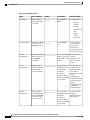
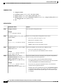
This table describes the main command modes, how to access each one, the prompt you see in that mode, and
how to exit the mode.
Catalyst 2960-X Switch Network Management Configuration Guide, Cisco IOS Release 15.0(2)EX
OL-29044-01
1
Using the Command-Line Interface
Command Modes
Table 1: Command Mode Summary
Mode
Access Method
User EXEC
Begin a session
using Telnet, SSH,
or console.
Prompt
Exit Method
About This Mode
Switch>
Enter logout or
quit.
Use this mode to
• Change
terminal
settings.
• Perform basic
tests.
• Display
system
information.
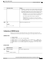
Privileged EXEC
While in user EXEC
mode, enter the
enable command.
Global
configuration
While in privileged
EXEC mode, enter
the configure
command.
VLAN
configuration
While in global
configuration mode,
enter the vlan
vlan-id command.
Interface
configuration
While in global
configuration mode,
enter the interface
command (with a
specific interface).
Switch#
Switch(config)#
Switch(config-vlan)#
Switch(config-if)#
Enter disable to
exit.
Use this mode to
verify commands
that you have
entered. Use a
password to protect
access to this mode.
To exit to privileged
EXEC mode, enter
exit or end, or press
Ctrl-Z.
Use this mode to
configure
parameters that
apply to the entire
switch.
To exit to global
configuration mode,
enter the exit
command.
Use this mode to
configure VLAN
parameters. When
VTP mode is
transparent, you can
To return to
create
privileged EXEC
extended-range
mode, press Ctrl-Z
VLANs (VLAN IDs
or enter end.
greater than 1005)
and save
configurations in the
switch startup
configuration file.
To exit to global
Use this mode to
configuration mode, configure
enter exit.
parameters for the
Ethernet ports.
To return to
privileged EXEC
mode, press Ctrl-Z
or enter end.
Catalyst 2960-X Switch Network Management Configuration Guide, Cisco IOS Release 15.0(2)EX
2
OL-29044-01
Using the Command-Line Interface
Using the Help System
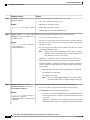
Mode
Access Method
Line configuration
While in global
configuration mode,
specify a line with
the line vty or line
console command.
Prompt
Exit Method
Switch(config-line)#
About This Mode
To exit to global
Use this mode to
configuration mode, configure
enter exit.
parameters for the
terminal line.
To return to
privileged EXEC
mode, press Ctrl-Z
or enter end.
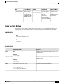
Using the Help System
You can enter a question mark (?) at the system prompt to display a list of commands available for each
command mode. You can also obtain a list of associated keywords and arguments for any command.
SUMMARY STEPS
1. help
2. abbreviated-command-entry ?
3. abbreviated-command-entry <Tab>
4. ?
5. command ?
6. command keyword ?
DETAILED STEPS
Step 1
Command or Action
Purpose
help
Obtains a brief description of the help system in any
command mode.
Example:
Switch# help
Step 2
abbreviated-command-entry ?
Obtains a list of commands that begin with a particular
character string.
Example:
Switch# di?
dir disable disconnect
Step 3
abbreviated-command-entry <Tab>
Completes a partial command name.
Example:
Switch# sh conf<tab>
Switch# show configuration
Catalyst 2960-X Switch Network Management Configuration Guide, Cisco IOS Release 15.0(2)EX
OL-29044-01
3
Using the Command-Line Interface
Understanding Abbreviated Commands
Step 4
Command or Action
Purpose
?
Lists all commands available for a particular command
mode.
Example:
Switch> ?
Step 5
command ?
Lists the associated keywords for a command.
Example:
Switch> show ?
Step 6
command keyword ?
Lists the associated arguments for a keyword.
Example:
Switch(config)# cdp holdtime ?
<10-255> Length of time (in sec) that receiver
must keep this packet
Understanding Abbreviated Commands
You need to enter only enough characters for the switch to recognize the command as unique.
This example shows how to enter the show configuration privileged EXEC command in an abbreviated form:
Switch# show conf
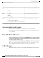
No and default Forms of Commands
Almost every configuration command also has a no form. In general, use the no form to disable a feature or
function or reverse the action of a command. For example, the no shutdown interface configuration command
reverses the shutdown of an interface. Use the command without the keyword no to reenable a disabled feature
or to enable a feature that is disabled by default.
Configuration commands can also have a default form. The default form of a command returns the command
setting to its default. Most commands are disabled by default, so the default form is the same as the no form.
However, some commands are enabled by default and have variables set to certain default values. In these
cases, the default command enables the command and sets variables to their default values.
CLI Error Messages
This table lists some error messages that you might encounter while using the CLI to configure your switch.
Catalyst 2960-X Switch Network Management Configuration Guide, Cisco IOS Release 15.0(2)EX
4
OL-29044-01
Using the Command-Line Interface
Configuration Logging
Table 2: Common CLI Error Messages
Error Message
Meaning
How to Get Help
% Ambiguous command: "show
con"
You did not enter enough
characters for your switch to
recognize the command.
Reenter the command followed by
a question mark (?) with a space
between the command and the
question mark.
The possible keywords that you can
enter with the command appear.
% Incomplete command.
You did not enter all the keywords Reenter the command followed by
or values required by this
a question mark (?) with a space
command.
between the command and the
question mark.
The possible keywords that you can
enter with the command appear.
% Invalid input detected at
‘^’ marker.
You entered the command
Enter a question mark (?) to display
incorrectly. The caret (^) marks the all the commands that are available
point of the error.
in this command mode.
The possible keywords that you can
enter with the command appear.
Configuration Logging
You can log and view changes to the switch configuration. You can use the Configuration Change Logging
and Notification feature to track changes on a per-session and per-user basis. The logger tracks each
configuration command that is applied, the user who entered the command, the time that the command was
entered, and the parser return code for the command. This feature includes a mechanism for asynchronous
notification to registered applications whenever the configuration changes. You can choose to have the
notifications sent to the syslog.
Note
Only CLI or HTTP changes are logged.
How to Use the CLI to Configure Features
Configuring the Command History
The software provides a history or record of commands that you have entered. The command history feature
is particularly useful for recalling long or complex commands or entries, including access lists. You can
customize this feature to suit your needs.
Catalyst 2960-X Switch Network Management Configuration Guide, Cisco IOS Release 15.0(2)EX
OL-29044-01
5
Using the Command-Line Interface
Configuring the Command History
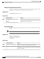
Changing the Command History Buffer Size
By default, the switch records ten command lines in its history buffer. You can alter this number for a current
terminal session or for all sessions on a particular line. This procedure is optional.
SUMMARY STEPS
1. terminal history [size number-of-lines]
DETAILED STEPS
Step 1
Command or Action
Purpose
terminal history [size number-of-lines]
Changes the number of command lines that the switch records during
the current terminal session in the privileged EXEC mode. You can
configure the size from 0 through 256.
Example:
Switch# terminal history size 200
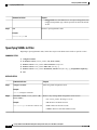
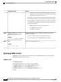
Recalling Commands
To recall commands from the history buffer, perform one of the actions listed in this table. These actions are
optional.
Note
The arrow keys function only on ANSI-compatible terminals such as VT100s.
SUMMARY STEPS
1. Ctrl-P or use the up arrow key
2. Ctrl-N or use the down arrow key
3. show history
DETAILED STEPS
Command or Action
Purpose
Step 1
Ctrl-P or use the up arrow key
Recalls commands in the history buffer, beginning with the most recent command.
Repeat the key sequence to recall successively older commands.
Step 2
Ctrl-N or use the down arrow key Returns to more recent commands in the history buffer after recalling commands
with Ctrl-P or the up arrow key. Repeat the key sequence to recall successively
more recent commands.
Catalyst 2960-X Switch Network Management Configuration Guide, Cisco IOS Release 15.0(2)EX
6
OL-29044-01
Using the Command-Line Interface
Enabling and Disabling Editing Features
Step 3
Command or Action
Purpose
show history
Lists the last several commands that you just entered in privileged EXEC mode.
The number of commands that appear is controlled by the setting of the terminal
history global configuration command and the history line configuration
command.
Example:
Switch# show history
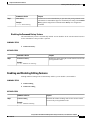
Disabling the Command History Feature
The command history feature is automatically enabled. You can disable it for the current terminal session or
for the command line. This procedure is optional.
SUMMARY STEPS
1. terminal no history
DETAILED STEPS
Step 1
Command or Action
Purpose
terminal no history
Disables the feature during the current terminal session in the
privileged EXEC mode.
Example:
Switch# terminal no history
Enabling and Disabling Editing Features
Although enhanced editing mode is automatically enabled, you can disable it, and reenable it.
SUMMARY STEPS
1. terminal editing
2. terminal no editing
DETAILED STEPS
Step 1
Command or Action
Purpose
terminal editing
Reenables the enhanced editing mode for the current terminal
session in the privileged EXEC mode.
Example:
Switch# terminal editing
Catalyst 2960-X Switch Network Management Configuration Guide, Cisco IOS Release 15.0(2)EX
OL-29044-01
7
Using the Command-Line Interface
Enabling and Disabling Editing Features
Step 2
Command or Action
Purpose
terminal no editing
Disables the enhanced editing mode for the current terminal session
in the privileged EXEC mode.
Example:
Switch# terminal no editing
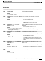
Editing Commands through Keystrokes
The keystrokes help you to edit the command lines. These keystrokes are optional.
Note
The arrow keys function only on ANSI-compatible terminals such as VT100s.
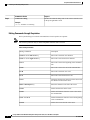
Table 3: Editing Commands
Editing Commands
Description
Ctrl-B or use the left arrow key
Moves the cursor back one character.
Ctrl-F or use the right arrow key
Moves the cursor forward one character.
Ctrl-A
Moves the cursor to the beginning of the command
line.
Ctrl-E
Moves the cursor to the end of the command line.
Esc B
Moves the cursor back one word.
Esc F
Moves the cursor forward one word.
Ctrl-T
Transposes the character to the left of the cursor with
the character located at the cursor.
Delete or Backspace key
Erases the character to the left of the cursor.
Ctrl-D
Deletes the character at the cursor.
Ctrl-K
Deletes all characters from the cursor to the end of
the command line.
Ctrl-U or Ctrl-X
Deletes all characters from the cursor to the beginning
of the command line.
Ctrl-W
Deletes the word to the left of the cursor.
Catalyst 2960-X Switch Network Management Configuration Guide, Cisco IOS Release 15.0(2)EX
8
OL-29044-01
Using the Command-Line Interface
Enabling and Disabling Editing Features
Esc D
Deletes from the cursor to the end of the word.
Esc C
Capitalizes at the cursor.
Esc L
Changes the word at the cursor to lowercase.
Esc U
Capitalizes letters from the cursor to the end of the
word.
Ctrl-V or Esc Q
Designates a particular keystroke as an executable
command, perhaps as a shortcut.
Return key
Scrolls down a line or screen on displays that are
longer than the terminal screen can display.
Note
The More prompt is used for any output that
has more lines than can be displayed on the
terminal screen, including show command
output. You can use the Return and Space
bar keystrokes whenever you see the More
prompt.
Space bar
Scrolls down one screen.
Ctrl-L or Ctrl-R
Redisplays the current command line if the switch
suddenly sends a message to your screen.
Editing Command Lines That Wrap
You can use a wraparound feature for commands that extend beyond a single line on the screen. When the
cursor reaches the right margin, the command line shifts ten spaces to the left. You cannot see the first ten
characters of the line, but you can scroll back and check the syntax at the beginning of the command. The
keystroke actions are optional.
To scroll back to the beginning of the command entry, press Ctrl-B or the left arrow key repeatedly. You can
also press Ctrl-A to immediately move to the beginning of the line.
Note
The arrow keys function only on ANSI-compatible terminals such as VT100s.
The following example shows how to wrap a command line that extend beyond a single line on the screen.
SUMMARY STEPS
1. access-list
2. Ctrl-A
3. Return key
Catalyst 2960-X Switch Network Management Configuration Guide, Cisco IOS Release 15.0(2)EX
OL-29044-01
9
Using the Command-Line Interface
Searching and Filtering Output of show and more Commands
DETAILED STEPS
Step 1
Command or Action
Purpose
access-list
Displays the global configuration command entry that extends beyond
one line.
Example:
When the cursor first reaches the end of the line, the line is shifted ten
spaces to the left and redisplayed. The dollar sign ($) shows that the
line has been scrolled to the left. Each time the cursor reaches the end
of the line, the line is again shifted ten spaces to the left.
Switch(config)# access-list 101 permit tcp
10.15.22.25 255.255.255.0 10.15.22.35
Switch(config)# $ 101 permit tcp
10.15.22.25 255.255.255.0 10.15.22.35
255.25
Switch(config)# $t tcp 10.15.22.25
255.255.255.0 131.108.1.20 255.255.255.0
eq
Switch(config)# $15.22.25 255.255.255.0
10.15.22.35 255.255.255.0 eq 45
Step 2
Ctrl-A
Checks the complete syntax.
Example:
The dollar sign ($) appears at the end of the line to show that the line
has been scrolled to the right.
Switch(config)# access-list 101 permit tcp
10.15.22.25 255.255.255.0 10.15.2$
Step 3
Return key
Execute the commands.
The software assumes that you have a terminal screen that is 80 columns
wide. If you have a different width, use the terminal width privileged
EXEC command to set the width of your terminal.
Use line wrapping with the command history feature to recall and
modify previous complex command entries.
Searching and Filtering Output of show and more Commands
You can search and filter the output for show and more commands. This is useful when you need to sort
through large amounts of output or if you want to exclude output that you do not need to see. Using these
commands is optional.
SUMMARY STEPS
1. {show | more} command | {begin | include | exclude} regular-expression
DETAILED STEPS
Step 1
Command or Action
Purpose
{show | more} command | {begin | include | exclude}
regular-expression
Searches and filters the output.
Catalyst 2960-X Switch Network Management Configuration Guide, Cisco IOS Release 15.0(2)EX
10
OL-29044-01
Using the Command-Line Interface
Accessing the CLI through a Console Connection or through Telnet
Command or Action
Purpose
Example:
Expressions are case sensitive. For example, if you enter
| exclude output, the lines that contain output are not
displayed, but the lines that contain output appear.
Switch# show interfaces | include protocol
Vlan1 is up, line protocol is up
Vlan10 is up, line protocol is down
GigabitEthernet1/0/1 is up, line protocol is down
GigabitEthernet1/0/2 is up, line protocol is up
Accessing the CLI through a Console Connection or through Telnet
Before you can access the CLI, you must connect a terminal or a PC to the switch console or connect a PC to
the Ethernet management port and then power on the switch, as described in the hardware installation guide
that shipped with your switch.
If your switch is already configured, you can access the CLI through a local console connection or through a
remote Telnet session, but your switch must first be configured for this type of access.
You can use one of these methods to establish a connection with the switch:
• Connect the switch console port to a management station or dial-up modem, or connect the Ethernet
management port to a PC. For information about connecting to the console or Ethernet management
port, see the switch hardware installation guide.
• Use any Telnet TCP/IP or encrypted Secure Shell (SSH) package from a remote management station.
The switch must have network connectivity with the Telnet or SSH client, and the switch must have an
enable secret password configured.
• The switch supports up to 16 simultaneous Telnet sessions. Changes made by one Telnet user are
reflected in all other Telnet sessions.
• The switch supports up to five simultaneous secure SSH sessions.
After you connect through the console port, through the Ethernet management port, through a Telnet
session or through an SSH session, the user EXEC prompt appears on the management station.
Catalyst 2960-X Switch Network Management Configuration Guide, Cisco IOS Release 15.0(2)EX
OL-29044-01
11
Using the Command-Line Interface
Accessing the CLI through a Console Connection or through Telnet
Catalyst 2960-X Switch Network Management Configuration Guide, Cisco IOS Release 15.0(2)EX
12
OL-29044-01
CHAPTER
2
Configuring Cisco IOS Configuration Engine
This chapter describes how to configure the Cisco IOS Configuration Engine.
• Finding Feature Information, page 13
• Prerequisites for Configuring the Configuration Engine, page 13
• Restrictions for Configuring the Configuration Engine, page 14
• Information About Configuring the Configuration Engine, page 14
• How to Configure the Configuration Engine, page 20
• Monitoring CNS Configurations, page 31
• Additional References, page 32
• Feature History and Information for the Configuration Engine, page 32
Finding Feature Information
Your software release may not support all the features documented in this module. For the latest feature
information and caveats, see the release notes for your platform and software release.
Use Cisco Feature Navigator to find information about platform support and Cisco software image support.
To access Cisco Feature Navigator, go to http://www.cisco.com/go/cfn. An account on Cisco.com is not
required.
Prerequisites for Configuring the Configuration Engine
• Obtain the name of the configuration engine instance to which you are connecting.
• Because the CNS uses both the event bus and the configuration server to provide configurations to
devices, you must define both ConfigID and Device ID for each configured switch.
• All switches configured with the cns config partial global configuration command must access the
event bus. The DeviceID, as originated on the switch, must match the DeviceID of the corresponding
switch definition in the Cisco Configuration Engine. You must know the hostname of the event bus to
which you are connecting.
Catalyst 2960-X Switch Network Management Configuration Guide, Cisco IOS Release 15.0(2)EX
OL-29044-01
13
Configuring Cisco IOS Configuration Engine
Restrictions for Configuring the Configuration Engine
Related Topics
Cisco Networking Services IDs and Device Hostnames, on page 16
DeviceID, on page 17
Restrictions for Configuring the Configuration Engine
• Within the scope of a single instance of the configuration server, no two configured switches can share
the same value for ConfigID.
• Within the scope of a single instance of the event bus, no two configured switches can share the same
value for DeviceID.
Related Topics
Cisco Networking Services IDs and Device Hostnames, on page 16
Information About Configuring the Configuration Engine
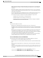
Cisco Configuration Engine Software
The Cisco Configuration Engine is network management utility software that acts as a configuration service
for automating the deployment and management of network devices and services. Each Cisco Configuration
Engine manages a group of Cisco devices (switches and routers) and the services that they deliver, storing
their configurations and delivering them as needed. The Cisco Configuration Engine automates initial
configurations and configuration updates by generating device-specific configuration changes, sending them
to the device, executing the configuration change, and logging the results.
The Cisco Configuration Engine supports standalone and server modes and has these Cisco Networking
Services (CNS) components:
• Configuration service:
◦Web server
◦File manager
◦Namespace mapping server
• Event service (event gateway)
• Data service directory (data models and schema)
Catalyst 2960-X Switch Network Management Configuration Guide, Cisco IOS Release 15.0(2)EX
14
OL-29044-01
Configuring Cisco IOS Configuration Engine
Configuration Service
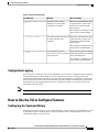
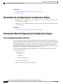
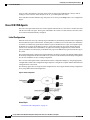
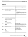
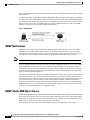
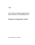
In standalone mode, the Cisco Configuration Engine supports an embedded directory service. In this mode,
no external directory or other data store is required. In server mode, the Cisco Configuration Engine supports
the use of a user-defined external directory.
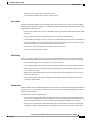
Figure 1: Cisco Configuration Engine Architectural Overview
Configuration Service
The Configuration Service is the core component of the Cisco Configuration Engine. It consists of a
Configuration Server that works with Cisco IOS CNS agents on the switch. The Configuration Service delivers
device and service configurations to the switch for initial configuration and mass reconfiguration by logical
groups. Switches receive their initial configuration from the Configuration Service when they start up on the
network for the first time.
The Configuration Service uses the CNS Event Service to send and receive configuration change events and
to send success and failure notifications.
The Configuration Server is a web server that uses configuration templates and the device-specific configuration
information stored in the embedded (standalone mode) or remote (server mode) directory.
Configuration templates are text files containing static configuration information in the form of CLI commands.
In the templates, variables are specified by using Lightweight Directory Access Protocol (LDAP) URLs that
reference the device-specific configuration information stored in a directory.
The Cisco IOS agent can perform a syntax check on received configuration files and publish events to show
the success or failure of the syntax check. The configuration agent can either apply configurations immediately
or delay the application until receipt of a synchronization event from the configuration server.
Catalyst 2960-X Switch Network Management Configuration Guide, Cisco IOS Release 15.0(2)EX
OL-29044-01
15
Configuring Cisco IOS Configuration Engine
Event Service
Event Service
The Cisco Configuration Engine uses the Event Service for receipt and generation of configuration events.
The Event Service consists of an event agent and an event gateway. The event agent is on the switch and
facilitates the communication between the switch and the event gateway on the Cisco Configuration Engine.
The Event Service is a highly capable publish-and-subscribe communication method. The Event Service uses
subject-based addressing to send messages to their destinations. Subject-based addressing conventions define
a simple, uniform namespace for messages and their destinations.
Related Topics
Enabling the CNS Event Agent, on page 20
NameSpace Mapper
The Cisco Configuration Engine includes the NameSpace Mapper (NSM) that provides a lookup service for
managing logical groups of devices based on application, device or group ID, and event.
Cisco IOS devices recognize only event subject-names that match those configured in Cisco IOS software;
for example, cisco.cns.config.load. You can use the namespace mapping service to designate events by using
any desired naming convention. When you have populated your data store with your subject names, NSM
changes your event subject-name strings to those known by Cisco IOS.
For a subscriber, when given a unique device ID and event, the namespace mapping service returns a set of
events to which to subscribe. Similarly, for a publisher, when given a unique group ID, device ID, and event,
the mapping service returns a set of events on which to publish.
Cisco Networking Services IDs and Device Hostnames
The Cisco Configuration Engine assumes that a unique identifier is associated with each configured switch.
This unique identifier can take on multiple synonyms, where each synonym is unique within a particular
namespace. The event service uses namespace content for subject-based addressing of messages.
The Cisco Configuration Engine intersects two namespaces, one for the event bus and the other for the
configuration server. Within the scope of the configuration server namespace, the term ConfigID is the unique
identifier for a device. Within the scope of the event bus namespace, the term DeviceID is the CNS unique
identifier for a device.
Related Topics
Prerequisites for Configuring the Configuration Engine, on page 13
Restrictions for Configuring the Configuration Engine, on page 14
ConfigID
Each configured switch has a unique ConfigID, which serves as the key into the Cisco Configuration Engine
directory for the corresponding set of switch CLI attributes. The ConfigID defined on the switch must match
the ConfigID for the corresponding switch definition on the Cisco Configuration Engine.
Catalyst 2960-X Switch Network Management Configuration Guide, Cisco IOS Release 15.0(2)EX
16
OL-29044-01
Configuring Cisco IOS Configuration Engine
Cisco Networking Services IDs and Device Hostnames
The ConfigID is fixed at startup time and cannot be changed until the device restarts, even if the switch
hostname is reconfigured.
DeviceID
Each configured switch participating on the event bus has a unique DeviceID, which is analogous to the switch
source address so that the switch can be targeted as a specific destination on the bus.
The origin of the DeviceID is defined by the Cisco IOS hostname of the switch. However, the DeviceID
variable and its usage reside within the event gateway adjacent to the switch.
The logical Cisco IOS termination point on the event bus is embedded in the event gateway, which in turn
functions as a proxy on behalf of the switch. The event gateway represents the switch and its corresponding
DeviceID to the event bus.
The switch declares its hostname to the event gateway immediately after the successful connection to the
event gateway. The event gateway couples the DeviceID value to the Cisco IOS hostname each time this
connection is established. The event gateway retains this DeviceID value for the duration of its connection to
the switch.
Related Topics
Prerequisites for Configuring the Configuration Engine, on page 13
Hostname and DeviceID
The DeviceID is fixed at the time of the connection to the event gateway and does not change even when the
switch hostname is reconfigured.
When changing the switch hostname on the switch, the only way to refresh the DeviceID is to break the
connection between the switch and the event gateway. For instructions on refreshing DeviceIDs, see "Related
Topics."
When the connection is reestablished, the switch sends its modified hostname to the event gateway. The event
gateway redefines the DeviceID to the new value.
Caution
When using the Cisco Configuration Engine user interface, you must first set the DeviceID field to the
hostname value that the switch acquires after, not before, and you must reinitialize the configuration for
your Cisco IOS CNS agent. Otherwise, subsequent partial configuration command operations may
malfunction.
Related Topics
Refreshing DeviceIDs, on page 28
Hostname, DeviceID, and ConfigID
In standalone mode, when a hostname value is set for a switch, the configuration server uses the hostname as
the DeviceID when an event is sent on hostname. If the hostname has not been set, the event is sent on the
cn=<value> of the device.
Catalyst 2960-X Switch Network Management Configuration Guide, Cisco IOS Release 15.0(2)EX
OL-29044-01
17
Configuring Cisco IOS Configuration Engine
Cisco IOS CNS Agents
In server mode, the hostname is not used. In this mode, the unique DeviceID attribute is always used for
sending an event on the bus. If this attribute is not set, you cannot update the switch.
These and other associated attributes (tag value pairs) are set when you run Setup on the Cisco Configuration
Engine.
Cisco IOS CNS Agents
The CNS event agent feature allows the switch to publish and subscribe to events on the event bus and works
with the Cisco IOS CNS agent. These agents, embedded in the switch Cisco IOS software, allow the switch
to be connected and automatically configured.
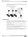
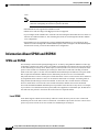
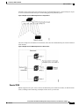
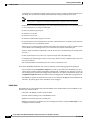
Initial Configuration
When the switch first comes up, it attempts to get an IP address by broadcasting a Dynamic Host Configuration
Protocol (DHCP) request on the network. Assuming there is no DHCP server on the subnet, the distribution
switch acts as a DHCP relay agent and forwards the request to the DHCP server. Upon receiving the request,
the DHCP server assigns an IP address to the new switch and includes the Trivial File Transfer Protocol
(TFTP) server Internet Protocol (IP) address, the path to the bootstrap configuration file, and the default
gateway IP address in a unicast reply to the DHCP relay agent. The DHCP relay agent forwards the reply to
the switch.
The switch automatically configures the assigned IP address on interface VLAN 1 (the default) and downloads
the bootstrap configuration file from the TFTP server. Upon successful download of the bootstrap configuration
file, the switch loads the file in its running configuration.
The Cisco IOS CNS agents initiate communication with the Configuration Engine by using the appropriate
ConfigID and EventID. The Configuration Engine maps the Config ID to a template and downloads the full
configuration file to the switch.
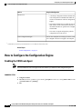
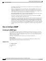
The following figure shows a sample network configuration for retrieving the initial bootstrap configuration
file by using DHCP-based autoconfiguration.
Figure 2: Initial Configuration
Related Topics
Automated CNS Configuration, on page 19
Catalyst 2960-X Switch Network Management Configuration Guide, Cisco IOS Release 15.0(2)EX
18
OL-29044-01
Configuring Cisco IOS Configuration Engine
Automated CNS Configuration
Incremental (Partial) Configuration
After the network is running, new services can be added by using the Cisco IOS CNS agent. Incremental
(partial) configurations can be sent to the switch. The actual configuration can be sent as an event payload by
way of the event gateway (push operation) or as a signal event that triggers the switch to initiate a pull operation.
The switch can check the syntax of the configuration before applying it. If the syntax is correct, the switch
applies the incremental configuration and publishes an event that signals success to the configuration server.
If the switch does not apply the incremental configuration, it publishes an event showing an error status. When
the switch has applied the incremental configuration, it can write it to nonvolatile random-access memory
(NVRAM) or wait until signaled to do so.
Synchronized Configuration
When the switch receives a configuration, it can defer application of the configuration upon receipt of a
write-signal event. The write-signal event tells the switch not to save the updated configuration into its
NVRAM. The switch uses the updated configuration as its running configuration. This ensures that the switch
configuration is synchronized with other network activities before saving the configuration in NVRAM for
use at the next reboot.
Automated CNS Configuration
To enable automated CNS configuration of the switch, you must first complete the prerequisites listed in this
topic. When you complete them, power on the switch. At the setup prompt, do nothing; the switch begins the
initial configuration. When the full configuration file is loaded on your switch, you do not need to do anything
else.
For more information on what happens during initial configuration, see "Related Topics."
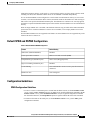
Table 4: Prerequisites for Enabling Automatic Configuration
Device
Required Configuration
Access switch
Factory default (no configuration file)
Distribution switch
• IP helper address
• Enable DHCP relay agent1
• IP routing (if used as default gateway)
DHCP server
• IP address assignment
• TFTP server IP address
• Path to bootstrap configuration file on the TFTP
server
• Default gateway IP address
Catalyst 2960-X Switch Network Management Configuration Guide, Cisco IOS Release 15.0(2)EX
OL-29044-01
19
Configuring Cisco IOS Configuration Engine
How to Configure the Configuration Engine
Device
Required Configuration
TFTP server
• A bootstrap configuration file that includes the
CNS configuration commands that enable the
switch to communicate with the Configuration
Engine
• The switch configured to use either the switch
MAC address or the serial number (instead of
the default hostname) to generate the ConfigID
and EventID
• The CNS event agent configured to push the
configuration file to the switch
CNS Configuration Engine
One or more templates for each type of device, with
the ConfigID of the device mapped to the template.
1 A DHCP Relay is needed only when the DHCP Server is on a different subnet from the client.
Related Topics
Initial Configuration, on page 18
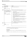
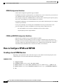
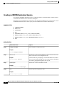
How to Configure the Configuration Engine
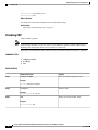
Enabling the CNS Event Agent
Note
You must enable the CNS event agent on the switch before you enable the CNS configuration agent.
Beginning in privileged EXEC mode, follow these steps to enable the CNS event agent on the switch.
SUMMARY STEPS
1. configure terminal
2. cns event {hostname | ip-address} [port-number] [ [keepalive seconds retry-count] [failover-time seconds
] [reconnect-time time] | backup]
3. end
Catalyst 2960-X Switch Network Management Configuration Guide, Cisco IOS Release 15.0(2)EX
20
OL-29044-01
Configuring Cisco IOS Configuration Engine
Enabling the CNS Event Agent
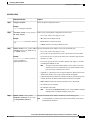
DETAILED STEPS
Step 1
Command or Action
Purpose
configure terminal
Enters the global configuration mode.
Example:
Switch# configure terminal
Step 2
cns event {hostname | ip-address}
[port-number] [ [keepalive seconds
retry-count] [failover-time seconds ]
[reconnect-time time] | backup]
Enables the event agent, and enters the gateway parameters.
• For {hostname | ip-address}, enter either the hostname or the IP address
of the event gateway.
• (Optional) For port number, enter the port number for the event gateway.
The default port number is 11011.
Example:
Switch(config)# cns event
10.180.1.27 keepalive 120 10
• (Optional) For keepalive seconds, enter how often the switch sends
keepalive messages. For retry-count, enter the number of unanswered
keepalive messages that the switch sends before the connection is
terminated. The default for each is 0.
• (Optional) For failover-time seconds, enter how long the switch waits for
the primary gateway route after the route to the backup gateway is
established.
• (Optional) For reconnect-time time, enter the maximum time interval that
the switch waits before trying to reconnect to the event gateway.
• (Optional) Enter backup to show that this is the backup gateway. (If
omitted, this is the primary gateway.)
Note
Step 3
Though visible in the command-line help string, the encrypt and the
clock-timeout time keywords are not supported.
Returns to privileged EXEC mode.
end
Example:
Switch(config)# end
This example shows how to enable the CNS event agent, set the IP address gateway to 10.180.1.27, set 120
seconds as the keepalive interval, and set 10 as the retry count.
Switch(config)# cns event 10.180.1.27 keepalive 120 10
What to Do Next
To verify information about the event agent, use the show cns event connections command in privileged
EXEC mode.
To disable the CNS event agent, use the no cns event { ip-address | hostname } global configuration command.
Catalyst 2960-X Switch Network Management Configuration Guide, Cisco IOS Release 15.0(2)EX
OL-29044-01
21
Configuring Cisco IOS Configuration Engine
Enabling the Cisco IOS CNS Agent
Related Topics
Event Service, on page 16
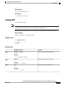
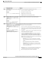
Enabling the Cisco IOS CNS Agent
Beginning in privileged EXEC mode, follow these steps to enable the Cisco IOS CNS agent on the switch.
Before You Begin
You must enable the CNS event agent on the switch before you enable this agent.
SUMMARY STEPS
1. configure terminal
2. cns config initial {hostname | ip-address} [port-number]
3. cns config partial {hostname | ip-address} [port-number]
4. end
5. Start the Cisco IOS CNS agent on the switch.
DETAILED STEPS
Step 1
Command or Action
Purpose
configure terminal
Enters the global configuration mode.
Example:
Switch# configure terminal
Step 2
cns config initial {hostname | ip-address}
[port-number]
Example:
Switch(config)# cns config initial
10.180.1.27 10
Enables the Cisco IOS CNS agent, and enters the configuration server
parameters.
• For {hostname | ip-address}, enter either the hostname or the
IP address of the configuration server.
• (Optional) For port number, enter the port number for the
configuration server.
This command enables the Cisco IOS CNS agent and initiates an initial
configuration on the switch.
Step 3
cns config partial {hostname | ip-address}
[port-number]
Example:
Switch(config)# cns config partial
10.180.1.27 10
Enables the Cisco IOS CNS agent, and enters the configuration server
parameters.
• For {hostname | ip-address}, enter either the hostname or the
IP address of the configuration server.
• (Optional) For port number, enter the port number for the
configuration server.
Catalyst 2960-X Switch Network Management Configuration Guide, Cisco IOS Release 15.0(2)EX
22
OL-29044-01
Configuring Cisco IOS Configuration Engine
Enabling an Initial Configuration for Cisco IOS CNS Agent
Command or Action
Purpose
Enables the Cisco IOS CNS agent and initiates a partial configuration
on the switch.
Step 4
Returns to privileged EXEC mode.
end
Example:
Switch(config)# end
Step 5
Start the Cisco IOS CNS agent on the switch.
What to Do Next
You can now use the Cisco Configuration Engine to remotely send incremental configurations to the switch.
Related Topics
Refreshing DeviceIDs, on page 28
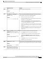
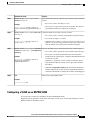
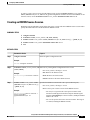
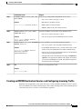
Enabling an Initial Configuration for Cisco IOS CNS Agent
Beginning in privileged EXEC mode, follow these steps to enable the CNS configuration agent and initiate
an initial configuration on the switch.
Catalyst 2960-X Switch Network Management Configuration Guide, Cisco IOS Release 15.0(2)EX
OL-29044-01
23
Configuring Cisco IOS Configuration Engine
Enabling an Initial Configuration for Cisco IOS CNS Agent
SUMMARY STEPS
1. configure terminal
2. cns template connect name
3. cli config-text
4. Repeat Steps 2 to 3 to configure another CNS connect template.
5. exit
6. cns connect name [retries number] [retry-interval seconds] [sleep seconds] [timeout seconds]
7. discover {controller controller-type | dlci [subinterface subinterface-number] | interface [interface-type]
| line line-type}
8. template name [... name]
9. Repeat Steps 7 to 8 to specify more interface parameters and CNS connect templates in the CNS connect
profile.
10. exit
11. hostname name
12. ip route network-number
13. cns id interface num {dns-reverse | ipaddress | mac-address} [event] [image]
14. cns id {hardware-serial | hostname | string string | udi} [event] [image]
15. cns config initial {hostname | ip-address} [port-number] [event] [no-persist] [page page] [source
ip-address] [syntax-check]
16. end
DETAILED STEPS
Step 1
Command or Action
Purpose
configure terminal
Enters the global configuration mode.
Example:
Switch# configure terminal
Step 2
cns template connect name
Enters CNS template connect configuration mode, and specifies the name
of the CNS connect template.
Example:
Switch(config)# cns template connect
template-dhcp
Step 3
cli config-text
Enters a command line for the CNS connect template. Repeat this step for
each command line in the template.
Example:
Switch(config-tmpl-conn)# cli ip
address dhcp
Step 4
Repeat Steps 2 to 3 to configure another
CNS connect template.
Catalyst 2960-X Switch Network Management Configuration Guide, Cisco IOS Release 15.0(2)EX
24
OL-29044-01
Configuring Cisco IOS Configuration Engine
Enabling an Initial Configuration for Cisco IOS CNS Agent
Step 5
Command or Action
Purpose
exit
Returns to global configuration mode.
Example:
Switch(config)# exit
Step 6
cns connect name [retries number]
[retry-interval seconds] [sleep seconds]
[timeout seconds]
Enters CNS connect configuration mode, specifies the name of the CNS
connect profile, and defines the profile parameters. The switch uses the CNS
connect profile to connect to the Configuration Engine.
• Enter the name of the CNS connect profile.
Example:
Switch(config)# cns connect dhcp
• (Optional) For retries number, enter the number of connection retries.
The range is 1 to 30. The default is 3.
• (Optional) For retry-interval seconds, enter the interval between
successive connection attempts to the Configuration Engine. The range
is 1 to 40 seconds. The default is 10 seconds.
• (Optional) For sleep seconds, enter the amount of time before which
the first connection attempt occurs. The range is 0 to 250 seconds. The
default is 0.
• (Optional) For timeout seconds, enter the amount of time after which
the connection attempts end. The range is 10 to 2000 seconds. The
default is 120.
Step 7
discover {controller controller-type | dlci Specifies the interface parameters in the CNS connect profile.
[subinterface subinterface-number] |
• For controller controller-type, enter the controller type.
interface [interface-type] | line line-type}
• For dlci, enter the active data-link connection identifiers (DLCIs).
Example:
Switch(config-cns-conn)# discover
interface gigabitethernet
(Optional) For subinterface subinterface-number, specify the
point-to-point subinterface number that is used to search for active
DLCIs.
• For interface [interface-type], enter the type of interface.
• For line line-type, enter the line type.
Step 8
template name [... name]
Specifies the list of CNS connect templates in the CNS connect profile to be
applied to the switch configuration. You can specify more than one template.
Example:
Switch(config-cns-conn)# template
template-dhcp
Step 9
Repeat Steps 7 to 8 to specify more
interface parameters and CNS connect
templates in the CNS connect profile.
Catalyst 2960-X Switch Network Management Configuration Guide, Cisco IOS Release 15.0(2)EX
OL-29044-01
25
Configuring Cisco IOS Configuration Engine
Enabling an Initial Configuration for Cisco IOS CNS Agent
Step 10
Command or Action
Purpose
exit
Returns to global configuration mode.
Example:
Switch(config-cns-conn)# exit
Step 11
hostname name
Enters the hostname for the switch.
Example:
Switch(config)# hostname device1
Step 12
ip route network-number
(Optional) Establishes a static route to the Configuration Engine whose IP
address is network-number.
Example:
RemoteSwitch(config)# ip route
172.28.129.22 255.255.255.255
11.11.11.1
Step 13
(Optional) Sets the unique EventID or ConfigID used by the Configuration
cns id interface num {dns-reverse |
ipaddress | mac-address} [event] [image] Engine. If you enter this command, do not enter the cns id {hardware-serial
| hostname | string string | udi} [event] [image] command.
Example:
RemoteSwitch(config)# cns id
GigabitEthernet1/0/1 ipaddress
• For interface num, enter the type of interface. For example, ethernet,
group-async, loopback, or virtual-template. This setting specifies from
which interface the IP or MAC address should be retrieved to define
the unique ID.
• For {dns-reverse | ipaddress | mac-address}, enter dns-reverse to
retrieve the hostname and assign it as the unique ID, enter ipaddress
to use the IP address, or enter mac-address to use the MAC address
as the unique ID.
• (Optional) Enter event to set the ID to be the event-id value used to
identify the switch.
• (Optional) Enter image to set the ID to be the image-id value used to
identify the switch.
Note
Step 14
cns id {hardware-serial | hostname |
string string | udi} [event] [image]
Example:
RemoteSwitch(config)# cns id
hostname
If both the event and image keywords are omitted, the image-id
value is used to identify the switch.
(Optional) Sets the unique EventID or ConfigID used by the Configuration
Engine. If you enter this command, do not enter the cns id interface num
{dns-reverse | ipaddress | mac-address} [event] [image] command.
• For { hardware-serial | hostname | string string | udi }, enter
hardware-serial to set the switch serial number as the unique ID, enter
hostname (the default) to select the switch hostname as the unique
ID, enter an arbitrary text string for string string as the unique ID, or
enter udi to set the unique device identifier (UDI) as the unique ID.
Catalyst 2960-X Switch Network Management Configuration Guide, Cisco IOS Release 15.0(2)EX
26
OL-29044-01
Configuring Cisco IOS Configuration Engine
Enabling an Initial Configuration for Cisco IOS CNS Agent
Command or Action
Step 15
Purpose
cns config initial {hostname | ip-address} Enables the Cisco IOS agent, and initiates an initial configuration.
[port-number] [event] [no-persist] [page
• For {hostname | ip-address}, enter the hostname or the IP address of
page] [source ip-address] [syntax-check]
the configuration server.
• (Optional) For port-number, enter the port number of the configuration
server. The default port number is 80.
Example:
RemoteSwitch(config)# cns config
initial 10.1.1.1 no-persist
• (Optional) Enable event for configuration success, failure, or warning
messages when the configuration is finished.
• (Optional) Enable no-persist to suppress the automatic writing to
NVRAM of the configuration pulled as a result of entering the cns
config initial global configuration command. If the no-persist keyword
is not entered, using the cns config initial command causes the resultant
configuration to be automatically written to NVRAM.
• (Optional) For page page, enter the web page of the initial configuration.
The default is /Config/config/asp.
• (Optional) Enter source ip-address to use for source IP address.
• (Optional) Enable syntax-check to check the syntax when this parameter
is entered.
Note
Step 16
Though visible in the command-line help string, the encrypt, status
url, and inventory keywords are not supported.
Returns to privileged EXEC mode.
end
Example:
RemoteSwitch(config)# end
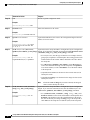
This example shows how to configure an initial configuration on a remote switch when the switch configuration
is unknown (the CNS Zero Touch feature).
Switch(config)# cns template connect template-dhcp
Switch(config-tmpl-conn)# cli ip address dhcp
Switch(config-tmpl-conn)# exit
Switch(config)# cns template connect ip-route
Switch(config-tmpl-conn)# cli ip route 0.0.0.0 0.0.0.0 ${next-hop}
Switch(config-tmpl-conn)# exit
Switch(config)# cns connect dhcp
Switch(config-cns-conn)# discover interface gigabitethernet
Switch(config-cns-conn)# template template-dhcp
Switch(config-cns-conn)# template ip-route
Switch(config-cns-conn)# exit
Switch(config)# hostname RemoteSwitch
RemoteSwitch(config)# cns config initial 10.1.1.1 no-persist
Catalyst 2960-X Switch Network Management Configuration Guide, Cisco IOS Release 15.0(2)EX
OL-29044-01
27
Configuring Cisco IOS Configuration Engine
Refreshing DeviceIDs
This example shows how to configure an initial configuration on a remote switch when the switch IP address
is known. The Configuration Engine IP address is 172.28.129.22.
Switch(config)# cns template connect template-dhcp
Switch(config-tmpl-conn)# cli ip address dhcp
Switch(config-tmpl-conn)# exit
Switch(config)# cns template connect ip-route
Switch(config-tmpl-conn)# cli ip route 0.0.0.0 0.0.0.0 ${next-hop}
Switch(config-tmpl-conn)# exit
Switch(config)# cns connect dhcp
Switch(config-cns-conn)# discover interface gigabitethernet
Switch(config-cns-conn)# template template-dhcp
Switch(config-cns-conn)# template ip-route
Switch(config-cns-conn)# exit
Switch(config)# hostname RemoteSwitch
RemoteSwitch(config)# ip route 172.28.129.22 255.255.255.255 11.11.11.1
RemoteSwitch(config)# cns id ethernet 0 ipaddress
RemoteSwitch(config)# cns config initial 172.28.129.22 no-persist
What to Do Next
To verify information about the configuration agent, use the show cns config connections command in
privileged EXEC mode.
To disable the CNS Cisco IOS agent, use the no cns config initial { ip-address | hostname } global configuration
command.
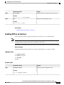
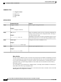
Refreshing DeviceIDs
Beginning in privileged EXEC mode, follow these steps to refresh a DeviceID when changing the hostname
on the switch.
SUMMARY STEPS
1. show cns config connections
2. Make sure that the CNS event agent is properly connected to the event gateway.
3. show cns event connections
4. Record from the output of Step 3 the information for the currently connected connection listed below.
You will be using the IP address and port number in subsequent steps of these instructions.
5. configure terminal
6. no cns event ip-address port-number
7. cns event ip-address port-number
8. end
9. Make sure that you have reestablished the connection between the switch and the event connection by
examining the output from show cns event connections.
Catalyst 2960-X Switch Network Management Configuration Guide, Cisco IOS Release 15.0(2)EX
28
OL-29044-01
Configuring Cisco IOS Configuration Engine
Refreshing DeviceIDs
DETAILED STEPS
Step 1
Command or Action
Purpose
show cns config connections
Displays whether the CNS event agent is connecting to the
gateway, connected, or active, and the gateway used by the
event agent, its IP address and port number.
Example:
Switch# show cns config connections
Step 2
Make sure that the CNS event agent is properly
connected to the event gateway.
Examine the output of show cns config connections for the
following:
• Connection is active.
• Connection is using the currently configured switch
hostname. The DeviceID will be refreshed to correspond
to the new hostname configuration using these
instructions.
Step 3
show cns event connections
Displays the event connection information for your switch.
Example:
Switch# show cns event connections
Step 4
Record from the output of Step 3 the information for
the currently connected connection listed below. You
will be using the IP address and port number in
subsequent steps of these instructions.
Step 5
configure terminal
Enters global configuration mode.
Example:
Switch# configure terminal
Step 6
no cns event ip-address port-number
Specifies the IP address and port number that you recorded
in Step 4 in this command.
Example:
This command breaks the connection between the switch and
the event gateway. It is necessary to first break, then
reestablish, this connection to refresh the DeviceID.
Switch(config)# no cns event 172.28.129.22 2012
Step 7
Step 8
cns event ip-address port-number
Specifies the IP address and port number that you recorded
in Step 4 in this command.
Example:
Switch(config)# cns event 172.28.129.22 2012
This command reestablishes the connection between the
switch and the event gateway.
end
Returns to privileged EXEC mode.
Example:
Switch(config)# end
Catalyst 2960-X Switch Network Management Configuration Guide, Cisco IOS Release 15.0(2)EX
OL-29044-01
29
Configuring Cisco IOS Configuration Engine
Enabling a Partial Configuration for Cisco IOS CNS Agent
Command or Action
Step 9
Purpose
Make sure that you have reestablished the connection
between the switch and the event connection by
examining the output from show cns event connections.
Related Topics
Enabling the Cisco IOS CNS Agent, on page 22
Hostname and DeviceID, on page 17
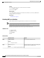
Enabling a Partial Configuration for Cisco IOS CNS Agent
Beginning in privileged EXEC mode, follow these steps to enable the Cisco IOS CNS agent and to initiate a
partial configuration on the switch.
SUMMARY STEPS
1. configure terminal
2. cns config partial {ip-address | hostname} [port-number] [source ip-address]
3. end
DETAILED STEPS
Step 1
Command or Action
Purpose
configure terminal
Enters the global configuration mode.
Example:
Switch# configure terminal
Step 2
cns config partial {ip-address | hostname}
[port-number] [source ip-address]
Example:
Switch(config)# cns config partial
172.28.129.22 2013
Enables the configuration agent, and initiates a partial configuration.
• For {ip-address | hostname}, enter the IP address or the hostname
of the configuration server.
• (Optional) For port-number, enter the port number of the
configuration server. The default port number is 80.
• (Optional) Enter source ip-address to use for the source IP
address.
Note
Though visible in the command-line help string, the encrypt
keyword is not supported.
Catalyst 2960-X Switch Network Management Configuration Guide, Cisco IOS Release 15.0(2)EX
30
OL-29044-01
Configuring Cisco IOS Configuration Engine
Monitoring CNS Configurations
Step 3
Command or Action
Purpose
end
Returns to privileged EXEC mode.
Example:
Switch(config)# end
What to Do Next
To verify information about the configuration agent, use either the show cns config stats or the show cns
config outstanding command in privileged EXEC mode.
To disable the Cisco IOS agent, use the no cns config partial { ip-address | hostname } global configuration
command. To cancel a partial configuration, use the cns config cancel global configuration command.
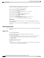
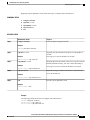
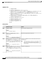
Monitoring CNS Configurations
Table 5: CNS show Commands
Command
Purpose
show cns config connections
Displays the status of the CNS Cisco IOS CNS agent
connections.
Switch# show cns config connections
Switch# show cns config outstanding
Displays information about incremental (partial) CNS
configurations that have started but are not yet
completed.
show cns config stats
Displays statistics about the Cisco IOS CNS agent.
show cns config outstanding
Switch# show cns config stats
show cns event connections
Displays the status of the CNS event agent
connections.
Switch# show cns event connections
show cns event gateway
Displays the event gateway information for your
switch.
Switch# show cns event gateway
show cns event stats
Displays statistics about the CNS event agent.
Switch# show cns event stats
show cns event subject
Displays a list of event agent subjects that are
subscribed to by applications.
Switch# show cns event subject
Catalyst 2960-X Switch Network Management Configuration Guide, Cisco IOS Release 15.0(2)EX
OL-29044-01
31
Configuring Cisco IOS Configuration Engine
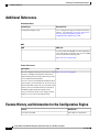
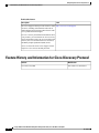
Additional References
Additional References
Related Documents
Related Topic
Document Title
Configuration Engine Setup
Cisco Configuration Engine Installation and Setup
Guide, 1.5 for Linux http://www.cisco.com/en/US/
docs/net_mgmt/configuration_engine/1.5/
installation_linux/guide/setup_1.html
MIBs
MIB
MIBs Link
To locate and download MIBs for selected platforms,
Cisco IOS releases, and feature sets, use Cisco MIB
Locator found at the following URL:
http://www.cisco.com/go/mibs
Technical Assistance
Description
Link
The Cisco Support website provides extensive online http://www.cisco.com/support
resources, including documentation and tools for
troubleshooting and resolving technical issues with
Cisco products and technologies.
To receive security and technical information about
your products, you can subscribe to various services,
such as the Product Alert Tool (accessed from Field
Notices), the Cisco Technical Services Newsletter,
and Really Simple Syndication (RSS) Feeds.
Access to most tools on the Cisco Support website
requires a Cisco.com user ID and password.
Feature History and Information for the Configuration Engine
Release
Modification
Cisco IOS 15.0(2)EX
This feature was introduced.
Catalyst 2960-X Switch Network Management Configuration Guide, Cisco IOS Release 15.0(2)EX
32
OL-29044-01
CHAPTER
3
Configuring the Cisco Discovery Protocol
This chapter describes the configuration of the Cisco Discovery Protocol (CDP).
• Finding Feature Information, page 33
• Information About CDP, page 33
• How to Configure CDP, page 34
• Monitoring and Maintaining CDP, page 40
• Additional References, page 41
• Feature History and Information for Cisco Discovery Protocol, page 42
Finding Feature Information
Your software release may not support all the features documented in this module. For the latest feature
information and caveats, see the release notes for your platform and software release.
Use Cisco Feature Navigator to find information about platform support and Cisco software image support.
To access Cisco Feature Navigator, go to http://www.cisco.com/go/cfn. An account on Cisco.com is not
required.
Information About CDP
CDP Overview
CDP is a device discovery protocol that runs over Layer 2 (the data-link layer) on all Cisco-manufactured
devices (routers, bridges, access servers, controllers, and switches) and allows network management applications
to discover Cisco devices that are neighbors of already known devices. With CDP, network management
applications can learn the device type and the Simple Network Management Protocol (SNMP) agent address
of neighboring devices running lower-layer, transparent protocols. This feature enables applications to send
SNMP queries to neighboring devices.
Catalyst 2960-X Switch Network Management Configuration Guide, Cisco IOS Release 15.0(2)EX
OL-29044-01
33
Configuring the Cisco Discovery Protocol
CDP and Stacks
CDP runs on all media that support Subnetwork Access Protocol (SNAP). Because CDP runs over the data-link
layer only, two systems that support different network-layer protocols can learn about each other.
Each CDP-configured device sends periodic messages to a multicast address, advertising at least one address
at which it can receive SNMP messages. The advertisements also contain time-to-live, or holdtime information,
which is the length of time a receiving device holds CDP information before discarding it. Each device also
listens to the messages sent by other devices to learn about neighboring devices.
On the switch, CDP enables Network Assistant to display a graphical view of the network. The switch uses
CDP to find cluster candidates and maintain information about cluster members and other devices up to three
cluster-enabled devices away from the command switch by default.
CDP and Stacks
A switch stack appears as a single switch in the network. Therefore, CDP discovers the switch stack, not the
individual stack members. The switch stack sends CDP messages to neighboring network devices when there
are changes to the switch stack membership, such as stack members being added or removed.
Default CDP Configuration
This table shows the default CDP configuration.
Feature
Default Setting
CDP global state
Enabled
CDP interface state
Enabled
CDP timer (packet update frequency)
60 seconds
CDP holdtime (before discarding)
180 seconds
CDP Version-2 advertisements
Enabled
How to Configure CDP
Configuring CDP Characteristics
You can configure these CDP characteristics:
• Frequency of CDP updates
• Amount of time to hold the information before discarding it
• Whether or not to send Version-2 advertisements
Note
Steps 2 through 4 are all optional and can be performed in any order.
Catalyst 2960-X Switch Network Management Configuration Guide, Cisco IOS Release 15.0(2)EX
34
OL-29044-01
Configuring the Cisco Discovery Protocol
Configuring CDP Characteristics
Beginning in privileged EXEC mode, follow these steps to configure these characteristics.
SUMMARY STEPS
1. configure terminal
2. cdp timer seconds
3. cdp holdtime seconds
4. cdp advertise-v2
5. end
DETAILED STEPS
Step 1
Command or Action
Purpose
configure terminal
Enters the global configuration mode.
Example:
Switch# configure terminal
Step 2
cdp timer seconds
(Optional) Sets the transmission frequency of CDP updates in
seconds.
Example:
The range is 5 to 254; the default is 60 seconds.
Switch(config)# cdp timer 20
Step 3
cdp holdtime seconds
(Optional) Specifies the amount of time a receiving device should
hold the information sent by your device before discarding it.
Example:
The range is 10 to 255 seconds; the default is 180 seconds.
Switch(config)# cdp holdtime 60
Step 4
(Optional) Configures CDP to send Version-2 advertisements.
cdp advertise-v2
This is the default state.
Example:
Switch(config)# cdp advertise-v2
Step 5
Returns to privileged EXEC mode.
end
Example:
Switch(config)# end
Example
The following example shows how to configure CDP characteristics:
Switch# configure terminal
Switch(config)# cdp timer 50
Switch(config)# cdp holdtime 120
Catalyst 2960-X Switch Network Management Configuration Guide, Cisco IOS Release 15.0(2)EX
OL-29044-01
35
Configuring the Cisco Discovery Protocol
Disabling CDP
Switch(config)# cdp advertise-v2
Switch(config)# end
What to Do Next
Use the no form of the CDP commands to return to the default settings.
Related Topics
Monitoring and Maintaining CDP, on page 40
Disabling CDP
CDP is enabled by default.
Note
Switch clusters and other Cisco devices (such as Cisco IP Phones) regularly exchange CDP messages.
Disabling CDP can interrupt cluster discovery and device connectivity.
Beginning in privileged EXEC mode, follow these steps to disable the CDP device discovery capability.
SUMMARY STEPS
1. configure terminal
2. no cdp run
3. end
DETAILED STEPS
Step 1
Command or Action
Purpose
configure terminal
Enters the global configuration mode.
Example:
Switch# configure terminal
Step 2
no cdp run
Disables CDP.
Example:
Switch(config)# no cdp run
Step 3
end
Returns to privileged EXEC mode.
Example:
Switch(config)# end
Catalyst 2960-X Switch Network Management Configuration Guide, Cisco IOS Release 15.0(2)EX
36
OL-29044-01
Configuring the Cisco Discovery Protocol
Enabling CDP
What to Do Next
You must reenable CDP to use it.
Related Topics
Enabling CDP, on page 37
Enabling CDP
CDP is enabled by default.
Note
Switch clusters and other Cisco devices (such as Cisco IP Phones) regularly exchange CDP messages.
Disabling CDP can interrupt cluster discovery and device connectivity.
Beginning in privileged EXEC mode, follow these steps to enable CDP when it has been disabled.
Before You Begin
CDP must be disabled, or it cannot be enabled.
SUMMARY STEPS
1. configure terminal
2. cdp run
3. end
DETAILED STEPS
Step 1
Command or Action
Purpose
configure terminal
Enters the global configuration mode.
Example:
Switch# configure terminal
Step 2
Enables CDP if it has been disabled.
cdp run
Example:
Switch(config)# cdp run
Step 3
Returns to privileged EXEC mode.
end
Example:
Switch(config)# end
Catalyst 2960-X Switch Network Management Configuration Guide, Cisco IOS Release 15.0(2)EX
OL-29044-01
37
Configuring the Cisco Discovery Protocol
Disabling CDP on an Interface
Example
The following example shows how to enable CDP if it has been disabled:
Switch# configure terminal
Switch(config)# cdp run
Switch(config)# end
What to Do Next
Use the show run all command to show that CDP has been enabled. If you enter only show run , the
enabling of CDP may not be displayed.
Related Topics
Disabling CDP, on page 36
Disabling CDP on an Interface
CDP is enabled by default on all supported interfaces to send and to receive CDP information.
Note
Switch clusters and other Cisco devices (such as Cisco IP Phones) regularly exchange CDP messages.
Disabling CDP can interrupt cluster discovery and device connectivity.
Beginning in privileged EXEC mode, follow these steps to disable CDP on a port.
SUMMARY STEPS
1. configure terminal
2. interface interface-id
3. no cdp enable
4. end
DETAILED STEPS
Step 1
Command or Action
Purpose
configure terminal
Enters the global configuration mode.
Example:
Switch# configure terminal
Step 2
interface interface-id
Specifies the interface on which you are disabling CDP,
and enters interface configuration mode.
Example:
Switch(config)# interface gigabitethernet1/0/1
Catalyst 2960-X Switch Network Management Configuration Guide, Cisco IOS Release 15.0(2)EX
38
OL-29044-01
Configuring the Cisco Discovery Protocol
Enabling CDP on an Interface
Step 3
Command or Action
Purpose
no cdp enable
Disables CDP on the interface specified in Step 2.
Example:
Switch(config-if)# no cdp enable
Step 4
Returns to privileged EXEC mode.
end
Example:
Switch(config-if)# end
Related Topics
Enabling CDP on an Interface, on page 39
Enabling CDP on an Interface
CDP is enabled by default on all supported interfaces to send and to receive CDP information.
Note
Switch clusters and other Cisco devices (such as Cisco IP Phones) regularly exchange CDP messages.
Disabling CDP can interrupt cluster discovery and device connectivity.
Beginning in privileged EXEC mode, follow these steps to enable CDP on a port on which it has been disabled.
Before You Begin
CDP must be disabled on the port that you are trying to CDP enable on, or it cannot be enabled.
SUMMARY STEPS
1. configure terminal
2. interface interface-id
3. cdp enable
4. end
DETAILED STEPS
Step 1
Command or Action
Purpose
configure terminal
Enters the global configuration mode.
Example:
Switch# configure terminal
Catalyst 2960-X Switch Network Management Configuration Guide, Cisco IOS Release 15.0(2)EX
OL-29044-01
39
Configuring the Cisco Discovery Protocol
Monitoring and Maintaining CDP
Step 2
Command or Action
Purpose
interface interface-id
Specifies the interface on which you are enabling CDP,
and enters interface configuration mode.
Example:
Switch(config)# interface gigabitethernet1/0/1
Step 3
Enables CDP on a disabled interface.
cdp enable
Example:
Switch(config-if)# cdp enable
Step 4
Returns to privileged EXEC mode.
end
Example:
Switch(config-if)# end
Example
The following example shows how to enable CDP on a disabled port:
Switch# configure terminal
Switch(config)# interface gigabitethernet1/0/1
Switch(config-if)# cdp enable
Switch(config-if)# end
Related Topics
Disabling CDP on an Interface, on page 38
Monitoring and Maintaining CDP
Table 6: Commands for Displaying CDP Information
Command
Description
clear cdp counters
Resets the traffic counters to zero.
clear cdp table
Deletes the CDP table of information about neighbors.
show cdp
Displays global information, such as frequency of transmissions
and the holdtime for packets being sent.
Catalyst 2960-X Switch Network Management Configuration Guide, Cisco IOS Release 15.0(2)EX
40
OL-29044-01
Configuring the Cisco Discovery Protocol
Additional References
Command
Description
show cdp entry entry-name [version]
[protocol]
Displays information about a specific neighbor.
You can enter an asterisk (*) to display all CDP neighbors, or
you can enter the name of the neighbor about which you want
information.
You can also limit the display to information about the protocols
enabled on the specified neighbor or information about the version
of software running on the device.
show cdp interface [interface-id]
Displays information about interfaces where CDP is enabled.
You can limit the display to the interface about which you want
information.
show cdp neighbors [interface-id]
[detail]
Displays information about neighbors, including device type,
interface type and number, holdtime settings, capabilities,
platform, and port ID.
You can limit the display to neighbors of a specific interface or
expand the display to provide more detailed information.
show cdp traffic
Displays CDP counters, including the number of packets sent
and received and checksum errors.
Related Topics
Configuring CDP Characteristics, on page 34
Additional References
Related Documents
Related Topic
Document Title
System Management Commands
Cisco IOS Configuration Fundamentals Command
Reference, Cisco IOS XE Release 3S (Catalyst 3850
Switches)
MIBs
MIB
MIBs Link
To locate and download MIBs for selected platforms,
Cisco IOS releases, and feature sets, use Cisco MIB
Locator found at the following URL:
http://www.cisco.com/go/mibs
Catalyst 2960-X Switch Network Management Configuration Guide, Cisco IOS Release 15.0(2)EX
OL-29044-01
41
Configuring the Cisco Discovery Protocol
Feature History and Information for Cisco Discovery Protocol
Technical Assistance
Description
Link
The Cisco Support website provides extensive online http://www.cisco.com/support
resources, including documentation and tools for
troubleshooting and resolving technical issues with
Cisco products and technologies.
To receive security and technical information about
your products, you can subscribe to various services,
such as the Product Alert Tool (accessed from Field
Notices), the Cisco Technical Services Newsletter,
and Really Simple Syndication (RSS) Feeds.
Access to most tools on the Cisco Support website
requires a Cisco.com user ID and password.
Feature History and Information for Cisco Discovery Protocol
Release
Modification
Cisco IOS 15.0(2)EX
This feature was introduced.
Catalyst 2960-X Switch Network Management Configuration Guide, Cisco IOS Release 15.0(2)EX
42
OL-29044-01
CHAPTER
4
Configuring Simple Network Management
Protocol
This chapter describes the Simple Network Management Protocol (SNMP) configuration.
• Finding Feature Information, page 43
• Prerequisites for SNMP, page 43
• Restrictions for SNMP, page 46
• Information About SNMP, page 46
• How to Configure SNMP, page 50
• Monitoring SNMP Status, page 62
• SNMP Examples, page 63
• Feature History and Information for Simple Network Management Protocol, page 64
Finding Feature Information
Your software release may not support all the features documented in this module. For the latest feature
information and caveats, see the release notes for your platform and software release.
Use Cisco Feature Navigator to find information about platform support and Cisco software image support.
To access Cisco Feature Navigator, go to http://www.cisco.com/go/cfn. An account on Cisco.com is not
required.
Prerequisites for SNMP
Supported SNMP Versions
This software release supports the following SNMP versions:
• SNMPv1—The Simple Network Management Protocol, a Full Internet Standard, defined in RFC 1157.
Catalyst 2960-X Switch Network Management Configuration Guide, Cisco IOS Release 15.0(2)EX
OL-29044-01
43
Configuring Simple Network Management Protocol
Prerequisites for SNMP
• SNMPv2C replaces the Party-based Administrative and Security Framework of SNMPv2Classic with
the community-string-based Administrative Framework of SNMPv2C while retaining the bulk retrieval
and improved error handling of SNMPv2Classic. It has these features:
◦SNMPv2—Version 2 of the Simple Network Management Protocol, a Draft Internet Standard,
defined in RFCs 1902 through 1907.
◦SNMPv2C—The community-string-based Administrative Framework for SNMPv2, an Experimental
Internet Protocol defined in RFC 1901.
• SNMPv3—Version 3 of the SNMP is an interoperable standards-based protocol defined in RFCs 2273
to 2275. SNMPv3 provides secure access to devices by authenticating and encrypting packets over the
network and includes these security features:
◦Message integrity—Ensures that a packet was not tampered with in transit.
◦Authentication—Determines that the message is from a valid source.
◦Encryption—Mixes the contents of a package to prevent it from being read by an unauthorized
source.
Note
To select encryption, enter the priv keyword.
Both SNMPv1 and SNMPv2C use a community-based form of security. The community of managers able to
access the agent’s MIB is defined by an IP address access control list and password.
SNMPv2C includes a bulk retrieval function and more detailed error message reporting to management
stations. The bulk retrieval function retrieves tables and large quantities of information, minimizing the number
of round-trips required. The SNMPv2C improved error-handling includes expanded error codes that distinguish
different kinds of error conditions; these conditions are reported through a single error code in SNMPv1. Error
return codes in SNMPv2C report the error type.
SNMPv3 provides for both security models and security levels. A security model is an authentication strategy
set up for a user and the group within which the user resides. A security level is the permitted level of security
within a security model. A combination of the security level and the security model determine which security
method is used when handling an SNMP packet. Available security models are SNMPv1, SNMPv2C, and
SNMPv3.
The following table identifies characteristics and compares different combinations of security models and
levels:
Table 7: SNMP Security Models and Levels
Model
Level
Authentication
Encryption
Result
SNMPv1
noAuthNoPriv
Community string
No
Uses a community
string match for
authentication.
SNMPv2C
noAuthNoPriv
Community string
No
Uses a community
string match for
authentication.
Catalyst 2960-X Switch Network Management Configuration Guide, Cisco IOS Release 15.0(2)EX
44
OL-29044-01
Configuring Simple Network Management Protocol
Prerequisites for SNMP
Model
Level
Authentication
Encryption
Result
SNMPv3
noAuthNoPriv
Username
No
Uses a username
match for
authentication.
SNMPv3
authNoPriv
Message Digest 5
(MD5) or Secure
Hash Algorithm
(SHA)
No
Provides
authentication based
on the HMAC-MD5
or HMAC-SHA
algorithms.
SNMPv3
authPriv
MD5 or SHA
Data Encryption
Standard (DES) or
Advanced
Encryption Standard
(AES)
Provides
authentication based
on the HMAC-MD5
or HMAC-SHA
algorithms.
Allows specifying
the User-based
Security Model
(USM) with these
encryption
algorithms:
• DES 56-bit
encryption in
addition to
authentication
based on the
CBC-DES
(DES-56)
standard.
• 3DES 168-bit
encryption
• AES 128-bit,
192-bit, or
256-bit
encryption
You must configure the SNMP agent to use the SNMP version supported by the management station. Because
an agent can communicate with multiple managers, you can configure the software to support communications
using SNMPv1, SNMPv2C, or SNMPv3.
Catalyst 2960-X Switch Network Management Configuration Guide, Cisco IOS Release 15.0(2)EX
OL-29044-01
45
Configuring Simple Network Management Protocol
Restrictions for SNMP
Restrictions for SNMP
Version Restrictions
• SNMPv1 does not support informs.
Information About SNMP
SNMP Overview
SNMP is an application-layer protocol that provides a message format for communication between managers
and agents. The SNMP system consists of an SNMP manager, an SNMP agent, and a management information
base (MIB). The SNMP manager can be part of a network management system (NMS) such as Cisco Prime
Infrastructure. The agent and MIB reside on the switch. To configure SNMP on the switch, you define the
relationship between the manager and the agent.
The SNMP agent contains MIB variables whose values the SNMP manager can request or change. A manager
can get a value from an agent or store a value into the agent. The agent gathers data from the MIB, the repository
for information about device parameters and network data. The agent can also respond to a manager's requests
to get or set data.
An agent can send unsolicited traps to the manager. Traps are messages alerting the SNMP manager to a
condition on the network. Traps can mean improper user authentication, restarts, link status (up or down),
MAC address tracking, closing of a TCP connection, loss of connection to a neighbor, or other significant
events.
The active switch handles the SNMP requests and traps for the whole switch stack. The active switch
transparently manages any requests or traps that are related to all stack members. When a new active switch
is elected, the new active switch continues to handle SNMP requests and traps as configured on the previous
active switch, assuming that IP connectivity to the SNMP management stations is still in place after the new
active switch has taken control.
SNMP Manager Functions
The SNMP manager uses information in the MIB to perform the operations described in the following table:
Table 8: SNMP Operations
Operation
Description
get-request
Retrieves a value from a specific variable.
get-next-request Retrieves a value from a variable within a table.2
get-bulk-request3 Retrieves large blocks of data, such as multiple rows in a table, that would otherwise
require the transmission of many small blocks of data.
get-response
Replies to a get-request, get-next-request, and set-request sent by an NMS.
Catalyst 2960-X Switch Network Management Configuration Guide, Cisco IOS Release 15.0(2)EX
46
OL-29044-01
Configuring Simple Network Management Protocol
SNMP Agent Functions
Operation
Description
set-request
Stores a value in a specific variable.
trap
An unsolicited message sent by an SNMP agent to an SNMP manager when some event
has occurred.
2 With this operation, an SNMP manager does not need to know the exact variable name. A sequential search is performed to find the needed variable from
within a table.
3 The get-bulk command only works with SNMPv2 or later.
SNMP Agent Functions
The SNMP agent responds to SNMP manager requests as follows:
• Get a MIB variable—The SNMP agent begins this function in response to a request from the NMS. The
agent retrieves the value of the requested MIB variable and responds to the NMS with that value.
• Set a MIB variable—The SNMP agent begins this function in response to a message from the NMS.
The SNMP agent changes the value of the MIB variable to the value requested by the NMS.
The SNMP agent also sends unsolicited trap messages to notify an NMS that a significant event has occurred
on the agent. Examples of trap conditions include, but are not limited to, when a port or module goes up or
down, when spanning-tree topology changes occur, and when authentication failures occur.
SNMP Community Strings
SNMP community strings authenticate access to MIB objects and function as embedded passwords. In order
for the NMS to access the switch, the community string definitions on the NMS must match at least one of
the three community string definitions on the switch.
A community string can have one of the following attributes:
• Read-only (RO)—Gives all objects in the MIB except the community strings read access to authorized
management stations, but does not allow write access.
• Read-write (RW)—Gives all objects in the MIB read and write access to authorized management stations,
but does not allow access to the community strings.
• When a cluster is created, the command switch manages the exchange of messages among member
switches and the SNMP application. The Network Assistant software appends the member switch number
(@esN, where N is the switch number) to the first configured RW and RO community strings on the
command switch and propagates them to the member switches.
SNMP MIB Variables Access
An example of an NMS is the Cisco Prime Infrastructure network management software. Cisco Prime
Infrastructure 2.0 software uses the switch MIB variables to set device variables and to poll devices on the
network for specific information. The results of a poll can be displayed as a graph and analyzed to troubleshoot
Catalyst 2960-X Switch Network Management Configuration Guide, Cisco IOS Release 15.0(2)EX
OL-29044-01
47
Configuring Simple Network Management Protocol
SNMP Notifications
internetworking problems, increase network performance, verify the configuration of devices, monitor traffic
loads, and more.
As shown in the figure, the SNMP agent gathers data from the MIB. The agent can send traps, or notification
of certain events, to the SNMP manager, which receives and processes the traps. Traps alert the SNMP manager
to a condition on the network such as improper user authentication, restarts, link status (up or down), MAC
address tracking, and so forth. The SNMP agent also responds to MIB-related queries sent by the SNMP
manager in get-request, get-next-request, and set-request format.
Figure 3: SNMP Network
SNMP Notifications
SNMP allows the switch to send notifications to SNMP managers when particular events occur. SNMP
notifications can be sent as traps or inform requests. In command syntax, unless there is an option in the
command to select either traps or informs, the keyword traps refers to either traps or informs, or both. Use
the snmp-server host command to specify whether to send SNMP notifications as traps or informs.
Note
SNMPv1 does not support informs.
Traps are unreliable because the receiver does not send an acknowledgment when it receives a trap, and the
sender cannot determine if the trap was received. When an SNMP manager receives an inform request, it
acknowledges the message with an SNMP response protocol data unit (PDU). If the sender does not receive
a response, the inform request can be sent again. Because they can be resent, informs are more likely than
traps to reach their intended destination.
The characteristics that make informs more reliable than traps also consume more resources in the switch and
in the network. Unlike a trap, which is discarded as soon as it is sent, an inform request is held in memory
until a response is received or the request times out. Traps are sent only once, but an inform might be resent
or retried several times. The retries increase traffic and contribute to a higher overhead on the network.
Therefore, traps and informs require a trade-off between reliability and resources. If it is important that the
SNMP manager receive every notification, use inform requests. If traffic on the network or memory in the
switch is a concern and notification is not required, use traps.
SNMP ifIndex MIB Object Values
In an NMS, the IF-MIB generates and assigns an interface index (ifIndex) object value that is a unique number
greater than zero to identify a physical or a logical interface. When the switch reboots or the switch software
is upgraded, the switch uses this same value for the interface. For example, if the switch assigns a port 2 an
ifIndex value of 10003, this value is the same after the switch reboots.
The switch uses one of the values in the following table to assign an ifIndex value to an interface:
Catalyst 2960-X Switch Network Management Configuration Guide, Cisco IOS Release 15.0(2)EX
48
OL-29044-01
Configuring Simple Network Management Protocol
Default SNMP Configuration
Table 9: ifIndex Values
Interface Type
ifIndex Range
SVI4
1–4999
EtherChannel
5001–5048
Tunnel
5078–5142
Physical (such as Gigabit Ethernet or SFP5-module interfaces) based on type and
port numbers
10000–14500
Null
14501
Loopback and Tunnel
24567+
4 SVI = switch virtual interface
5 SFP = small form-factor pluggable
Default SNMP Configuration
6
Feature
Default Setting
SNMP agent
Disabled6.
SNMP trap receiver
None configured.
SNMP traps
None enabled except the trap for TCP connections (tty).
SNMP version
If no version keyword is present, the default is Version 1.
SNMPv3 authentication
If no keyword is entered, the default is the noauth (noAuthNoPriv) security
level.
SNMP notification type
If no type is specified, all notifications are sent.
This is the default when the switch starts and the startup configuration does not have any snmp-server global configuration commands.
SNMP Configuration Guidelines
If the switch starts and the switch startup configuration has at least one snmp-server global configuration
command, the SNMP agent is enabled.
An SNMP group is a table that maps SNMP users to SNMP views. An SNMP user is a member of an SNMP
group. An SNMP host is the recipient of an SNMP trap operation. An SNMP engine ID is a name for the local
or remote SNMP engine.
When configuring SNMP, follow these guidelines:
• When configuring an SNMP group, do not specify a notify view. The snmp-server host global
configuration command auto-generates a notify view for the user and then adds it to the group associated
with that user. Modifying the group's notify view affects all users associated with that group.
Catalyst 2960-X Switch Network Management Configuration Guide, Cisco IOS Release 15.0(2)EX
OL-29044-01
49
Configuring Simple Network Management Protocol
How to Configure SNMP
• To configure a remote user, specify the IP address or port number for the remote SNMP agent of the
device where the user resides.
• Before you configure remote users for a particular agent, configure the SNMP engine ID, using the
snmp-server engineID global configuration command with the remote option. The remote agent's
SNMP engine ID and user password are used to compute the authentication and privacy digests. If you
do not configure the remote engine ID first, the configuration command fails.
• When configuring SNMP informs, you need to configure the SNMP engine ID for the remote agent in
the SNMP database before you can send proxy requests or informs to it.
• If a local user is not associated with a remote host, the switch does not send informs for the auth
(authNoPriv) and the priv (authPriv) authentication levels.
• Changing the value of the SNMP engine ID has significant results. A user's password (entered on the
command line) is converted to an MD5 or SHA security digest based on the password and the local
engine ID. The command-line password is then destroyed, as required by RFC 2274. Because of this
deletion, if the value of the engine ID changes, the security digests of SNMPv3 users become invalid,
and you need to reconfigure SNMP users by using the snmp-server user username global configuration
command. Similar restrictions require the reconfiguration of community strings when the engine ID
changes.
How to Configure SNMP
Disabling the SNMP Agent
The no snmp-server global configuration command disables all running versions (Version 1, Version 2C,
and Version 3) of the SNMP agent on the device. You reenable all versions of the SNMP agent by the first
snmp-server global configuration command that you enter. There is no Cisco IOS command specifically
designated for enabling SNMP.
Beginning in privileged EXEC mode, follow these steps to disable the SNMP agent.
Before You Begin
The SNMP Agent must be enabled before it can be disabled. The SNMP agent is enabled by the first
snmp-server global configuration command entered on the device.
SUMMARY STEPS
1. configure terminal
2. no snmp-server
3. end
Catalyst 2960-X Switch Network Management Configuration Guide, Cisco IOS Release 15.0(2)EX
50
OL-29044-01
Configuring Simple Network Management Protocol
Configuring Community Strings
DETAILED STEPS
Step 1
Command or Action
Purpose
configure terminal
Enters the global configuration mode.
Example:
Switch# configure terminal
Step 2
Disables the SNMP agent operation.
no snmp-server
Example:
Switch(config)# no snmp-server
Step 3
Returns to privileged EXEC mode.
end
Example:
Switch(config)# end
Configuring Community Strings
You use the SNMP community string to define the relationship between the SNMP manager and the agent.
The community string acts like a password to permit access to the agent on the switch. Optionally, you can
specify one or more of these characteristics associated with the string:
• An access list of IP addresses of the SNMP managers that are permitted to use the community string to
gain access to the agent
• A MIB view, which defines the subset of all MIB objects accessible to the given community
• Read and write or read-only permission for the MIB objects accessible to the community
Beginning in privileged EXEC mode, follow these steps to configure a community string on the switch.
SUMMARY STEPS
1. configure terminal
2. snmp-server community string [view view-name] [ro | rw] [access-list-number]
3. access-list access-list-number {deny | permit} source [source-wildcard]
4. end
Catalyst 2960-X Switch Network Management Configuration Guide, Cisco IOS Release 15.0(2)EX
OL-29044-01
51
Configuring Simple Network Management Protocol
Configuring Community Strings
DETAILED STEPS
Step 1
Command or Action
Purpose
configure terminal
Enters the global configuration mode.
Example:
Switch# configure terminal
Step 2
snmp-server community string
[view view-name] [ro | rw]
[access-list-number]
Example:
Switch(config)# snmp-server
community comaccess ro 4
Configures the community string.
The @ symbol is used for delimiting the context information. Avoid using
the @ symbol as part of the SNMP community string when configuring
this command.
• For string, specify a string that acts like a password and permits access to the
SNMP protocol. You can configure one or more community strings of any
length.
Note
• (Optional) For view-name, specify the view record accessible to the community.
• (Optional) Specify either read-only (ro) if you want authorized management
stations to retrieve MIB objects, or specify read-write (rw) if you want
authorized management stations to retrieve and modify MIB objects. By
default, the community string permits read-only access to all objects.
• (Optional) For access-list-number, enter an IP standard access list numbered
from 1 to 99 and 1300 to 1999.
Step 3
access-list access-list-number {deny (Optional) If you specified an IP standard access list number in Step 2, then create
| permit} source [source-wildcard] the list, repeating the command as many times as necessary.
Example:
Switch(config)# access-list 4
deny any
• For access-list-number, enter the access list number specified in Step 2.
• The deny keyword denies access if the conditions are matched. The permit
keyword permits access if the conditions are matched.
• For source, enter the IP address of the SNMP managers that are permitted to
use the community string to gain access to the agent.
• (Optional) For source-wildcard, enter the wildcard bits in dotted decimal
notation to be applied to the source. Place ones in the bit positions that you
want to ignore.
Recall that the access list is always terminated by an implicit deny statement for
everything.
Step 4
end
Returns to privileged EXEC mode.
Example:
Switch(config)# end
Catalyst 2960-X Switch Network Management Configuration Guide, Cisco IOS Release 15.0(2)EX
52
OL-29044-01
Configuring Simple Network Management Protocol
Configuring SNMP Groups and Users
This example shows how to assign the comaccess string to SNMP, to allow read-only access, and to specify
that IP access list 4 can use the community string to gain access to the switch SNMP agent:
Switch(config)# snmp-server community comaccess ro 4
What to Do Next
To disable access for an SNMP community, set the community string for that community to the null string
(do not enter a value for the community string).
To remove a specific community string, use the no snmp-server community string global configuration
command.
You can specify an identification name (engine ID) for the local or remote SNMP server engine on the switch.
You can configure an SNMP server group that maps SNMP users to SNMP views, and you can add new users
to the SNMP group.
Configuring SNMP Groups and Users
You can specify an identification name (engine ID) for the local or remote SNMP server engine on the switch.
You can configure an SNMP server group that maps SNMP users to SNMP views, and you can add new users
to the SNMP group.
Beginning in privileged EXEC mode, follow these steps to configure SNMP groups and users on the switch.
SUMMARY STEPS
1. configure terminal
2. snmp-server engineID {local engineid-string | remote ip-address [udp-port port-number] engineid-string}
3. snmp-server group group-name {v1 | v2c | v3 {auth | noauth | priv}} [read readview] [write writeview]
[notify notifyview] [access access-list]
4. snmp-server user username group-name {remote host [ udp-port port]} {v1 [access access-list] | v2c
[access access-list] | v3 [encrypted] [access access-list] [auth {md5 | sha} auth-password] } [priv {des
| 3des | aes {128 | 192 | 256}} priv-password]
5. end
DETAILED STEPS
Command or Action
Purpose
Step 1 configure terminal
Enters the global configuration mode.
Example:
Switch# configure terminal
Step 2 snmp-server engineID {local
engineid-string | remote ip-address
Configures a name for either the local or remote copy of SNMP.
Catalyst 2960-X Switch Network Management Configuration Guide, Cisco IOS Release 15.0(2)EX
OL-29044-01
53
Configuring Simple Network Management Protocol
Configuring SNMP Groups and Users
Command or Action
[udp-port port-number]
engineid-string}
Example:
Switch(config)# snmp-server
engineID local 1234
Purpose
• The engineid-string is a 24-character ID string with the name of the copy of
SNMP. You need not specify the entire 24-character engine ID if it has trailing
zeros. Specify only the portion of the engine ID up to the point where only
zeros remain in the value. The Step Example configures an engine ID of
123400000000000000000000.
• If you select remote, specify the ip-address of the device that contains the
remote copy of SNMP and the optional User Datagram Protocol (UDP) port
on the remote device. The default is 162.
Step 3 snmp-server group group-name {v1 | Configures a new SNMP group on the remote device.
v2c | v3 {auth | noauth | priv}} [read For group-name, specify the name of the group.
readview] [write writeview] [notify
Specify one of the following security models:
notifyview] [access access-list]
• v1 is the least secure of the possible security models.
Example:
Switch(config)# snmp-server group
public v2c access lmnop
• v2c is the second least secure model. It allows transmission of informs and
integers twice the normal width.
• v3, the most secure, requires you to select one of the following authentication
levels:
auth—Enables the Message Digest 5 (MD5) and the Secure Hash Algorithm
(SHA) packet authentication.
noauth—Enables the noAuthNoPriv security level. This is the default if no
keyword is specified.
priv—Enables Data Encryption Standard (DES) packet encryption (also called
privacy).
(Optional) Enter read readview with a string (not to exceed 64 characters) that is
the name of the view in which you can only view the contents of the agent.
(Optional) Enter write writeview with a string (not to exceed 64 characters) that is
the name of the view in which you enter data and configure the contents of the agent.
(Optional) Enter notify notifyview with a string (not to exceed 64 characters) that
is the name of the view in which you specify a notify, inform, or trap.
(Optional) Enter access access-list with a string (not to exceed 64 characters) that
is the name of the access list.
Step 4 snmp-server user username
group-name {remote host [ udp-port
port]} {v1 [access access-list] | v2c
[access access-list] | v3 [encrypted]
[access access-list] [auth {md5 | sha}
auth-password] } [priv {des | 3des | aes
{128 | 192 | 256}} priv-password]
Adds a new user for an SNMP group.
The username is the name of the user on the host that connects to the agent.
The group-name is the name of the group to which the user is associated.
Enter remote to specify a remote SNMP entity to which the user belongs and the
hostname or IP address of that entity with the optional UDP port number. The default
is 162.
Catalyst 2960-X Switch Network Management Configuration Guide, Cisco IOS Release 15.0(2)EX
54
OL-29044-01
Configuring Simple Network Management Protocol
Configuring SNMP Notifications
Command or Action
Purpose
Example:
Enter the SNMP version number (v1, v2c, or v3). If you enter v3, you have these
additional options:
Switch(config)# snmp-server user
Pat public v2c
• encrypted specifies that the password appears in encrypted format. This
keyword is available only when the v3 keyword is specified.
• auth is an authentication level setting session that can be either the
HMAC-MD5-96 (md5) or the HMAC-SHA-96 (sha) authentication level and
requires a password string auth-password (not to exceed 64 characters).
If you enter v3 you can also configure a private (priv) encryption algorithm and
password string priv-password using the following keywords (not to exceed 64
characters):
• priv specifies the User-based Security Model (USM).
• des specifies the use of the 56-bit DES algorithm.
• 3des specifies the use of the 168-bit DES algorithm.
• aes specifies the use of the DES algorithm. You must select either 128-bit,
192-bit, or 256-bit encryption.
(Optional) Enter access access-list with a string (not to exceed 64 characters) that
is the name of the access list.
Step 5 end
Returns to privileged EXEC mode.
Example:
Switch(config)# end
Configuring SNMP Notifications
A trap manager is a management station that receives and processes traps. Traps are system alerts that the
switch generates when certain events occur. By default, no trap manager is defined, and no traps are sent.
Switches running this Cisco IOS release can have an unlimited number of trap managers.
Note
Many commands use the word traps in the command syntax. Unless there is an option in the command
to select either traps or informs, the keyword traps refers to traps, informs, or both. Use the snmp-server
host global configuration command to specify whether to send SNMP notifications as traps or informs.
You can use the snmp-server host global configuration command for a specific host to receive the notification
types listed in the following table. You can enable any or all of these traps and configure a trap manager to
receive them.
Catalyst 2960-X Switch Network Management Configuration Guide, Cisco IOS Release 15.0(2)EX
OL-29044-01
55
Configuring Simple Network Management Protocol
Configuring SNMP Notifications
Table 10: Device Notification Types
Notification Type Keyword
Description
bgp
Generates Border Gateway Protocol (BGP) state change traps. This
option is only available when the IP services feature set is enabled.
bridge
Generates STP bridge MIB traps.
cluster
Generates a trap when the cluster configuration changes.
config
Generates a trap for SNMP configuration changes.
copy-config
Generates a trap for SNMP copy configuration changes.
cpu threshold
Allow CPU-related traps.
entity
Generates a trap for SNMP entity changes.
envmon
Generates environmental monitor traps. You can enable any or all
of these environmental traps: fan, shutdown, status, supply,
temperature.
flash
Generates SNMP FLASH notifications. In a switch stack, you can
optionally enable notification for flash insertion or removal, which
would cause a trap to be issued whenever a switch in the stack is
removed or inserted (physical removal, power cycle, or reload).
fru-ctrl
Generates entity field-replaceable unit (FRU) control traps. In the
switch stack, this trap refers to the insertion or removal of a switch
in the stack.
hsrp
Generates a trap for Hot Standby Router Protocol (HSRP) changes.
ipmulticast
Generates a trap for IP multicast routing changes.
mac-notification
Generates a trap for MAC address notifications.
msdp
Generates a trap for Multicast Source Discovery Protocol (MSDP)
changes.
ospf
Generates a trap for Open Shortest Path First (OSPF) changes. You
can enable any or all of these traps: Cisco specific, errors, link-state
advertisement, rate limit, retransmit, and state changes.
pim
Generates a trap for Protocol-Independent Multicast (PIM) changes.
You can enable any or all of these traps: invalid PIM messages,
neighbor changes, and rendezvous point (RP)-mapping changes.
Catalyst 2960-X Switch Network Management Configuration Guide, Cisco IOS Release 15.0(2)EX
56
OL-29044-01
Configuring Simple Network Management Protocol
Configuring SNMP Notifications
Notification Type Keyword
Description
port-security
Generates SNMP port security traps. You can also set a maximum
trap rate per second. The range is from 0 to 1000; the default is 0,
which means that there is no rate limit.
When you configure a trap by using the notification type
port-security, configure the port security trap first, and
then configure the port security trap rate:
1 snmp-server enable traps port-security
Note
2 snmp-server enable traps port-security trap-rate rate
rtr
Generates a trap for the SNMP Response Time Reporter (RTR).
snmp
Generates a trap for SNMP-type notifications for authentication,
cold start, warm start, link up or link down.
storm-control
Generates a trap for SNMP storm-control. You can also set a
maximum trap rate per minute. The range is from 0 to 1000; the
default is 0 (no limit is imposed; a trap is sent at every occurrence).
stpx
Generates SNMP STP Extended MIB traps.
syslog
Generates SNMP syslog traps.
tty
Generates a trap for TCP connections. This trap is enabled by default.
vlan-membership
Generates a trap for SNMP VLAN membership changes.
vlancreate
Generates SNMP VLAN created traps.
vlandelete
Generates SNMP VLAN deleted traps.
vtp
Generates a trap for VLAN Trunking Protocol (VTP) changes.
Beginning in privileged EXEC mode, follow these steps to configure the switch to send traps or informs to a
host.
Catalyst 2960-X Switch Network Management Configuration Guide, Cisco IOS Release 15.0(2)EX
OL-29044-01
57
Configuring Simple Network Management Protocol
Configuring SNMP Notifications
SUMMARY STEPS
1. configure terminal
2. snmp-server engineID remote ip-address engineid-string
3. snmp-server user username group-name {remote host [ udp-port port]} {v1 [access access-list] | v2c
[access access-list] | v3 [encrypted] [access access-list] [auth {md5 | sha} auth-password] }
4. snmp-server group group-name {v1 | v2c | v3 {auth | noauth | priv}} [read readview] [write writeview]
[notify notifyview] [access access-list]
5. snmp-server host host-addr [informs | traps] [version {1 | 2c | 3 {auth | noauth | priv}}]
community-string [notification-type]
6. snmp-server enable traps notification-types
7. snmp-server trap-source interface-id
8. snmp-server queue-length length
9. snmp-server trap-timeout seconds
10. end
DETAILED STEPS
Step 1
Command or Action
Purpose
configure terminal
Enters the global configuration mode.
Example:
Switch# configure terminal
Step 2
snmp-server engineID remote ip-address
engineid-string
Specifies the engine ID for the remote host.
Example:
Switch(config)# snmp-server engineID remote
192.180.1.27 00000063000100a1c0b4011b
Step 3
snmp-server user username group-name {remote Configures an SNMP user to be associated with the remote host
host [ udp-port port]} {v1 [access access-list] | created in Step 2.
v2c [access access-list] | v3 [encrypted] [access Note
You cannot configure a remote user for an address without
access-list] [auth {md5 | sha} auth-password] }
first configuring the engine ID for the remote host.
Otherwise, you receive an error message, and the command
Example:
is not executed.
Switch(config)#
public v2c
Step 4
snmp-server user Pat
Configures an SNMP group.
snmp-server group group-name {v1 | v2c | v3
{auth | noauth | priv}} [read readview] [write
writeview] [notify notifyview] [access access-list]
Example:
Switch(config)# snmp-server group public
v2c access lmnop
Catalyst 2960-X Switch Network Management Configuration Guide, Cisco IOS Release 15.0(2)EX
58
OL-29044-01
Configuring Simple Network Management Protocol
Configuring SNMP Notifications
Step 5
Command or Action
Purpose
snmp-server host host-addr [informs | traps]
[version {1 | 2c | 3 {auth | noauth | priv}}]
community-string [notification-type]
Specifies the recipient of an SNMP trap operation.
Example:
Switch(config)# snmp-server host
203.0.113.1 comaccess snmp
For host-addr, specify the name or Internet address of the host (the
targeted recipient).
(Optional) Specify traps (the default) to send SNMP traps to the host.
Specify informs to send SNMP informs to the host.
(Optional) Specify the SNMP version (1, 2c, or 3). SNMPv1 does
not support informs.
(Optional) For Version 3, select authentication level auth, noauth,
or priv.
For community-string, when version 1 or version 2c is specified,
enter the password-like community string sent with the notification
operation. When version 3 is specified, enter the SNMPv3 username.
The @ symbol is used for delimiting the context information. Avoid
using the @ symbol as part of the SNMP community string when
configuring this command.
(Optional) For notification-type, use the keywords listed in the table
above. If no type is specified, all notifications are sent.
Step 6
snmp-server enable traps notification-types
Example:
Switch(config)# snmp-server enable traps
snmp
Enable the switch to send traps or informs and specify the type of
notifications to be sent. For a list of notification types, see the table
above, or enter snmp-server enable traps ?
To enable multiple types of traps, you must enter a separate
snmp-server enable traps command for each trap type.
Note
When you configure a trap by using the notification type
port-security, configure the port security trap first, and then
configure the port security trap rate:
1 snmp-server enable traps port-security
2 snmp-server enable traps port-security trap-rate rate
Step 7
snmp-server trap-source interface-id
Example:
(Optional) Specify the source interface, which provides the IP address
for the trap message. This command also sets the source IP address
for informs.
Switch(config)# snmp-server trap-source
GigabitEthernet1/0/1
Step 8
snmp-server queue-length length
(Optional) Establish the message queue length for each trap host. The
range is 1 to 1000; the default is 10.
Example:
Switch(config)# snmp-server queue-length
20
Catalyst 2960-X Switch Network Management Configuration Guide, Cisco IOS Release 15.0(2)EX
OL-29044-01
59
Configuring Simple Network Management Protocol
Setting the Agent Contact and Location Information
Step 9
Command or Action
Purpose
snmp-server trap-timeout seconds
(Optional) Define how often to resend trap messages. The range is 1
to 1000; the default is 30 seconds.
Example:
Switch(config)# snmp-server trap-timeout
60
Step 10
Returns to privileged EXEC mode.
end
Example:
Switch(config)# end
What to Do Next
The snmp-server host command specifies which hosts receive the notifications. The snmp-server enable
trap command globally enables the method for the specified notification (for traps and informs). To enable
a host to receive an inform, you must configure an snmp-server host informs command for the host and
globally enable informs by using the snmp-server enable traps command.
To remove the specified host from receiving traps, use the no snmp-server host host global configuration
command. The no snmp-server host command with no keywords disables traps, but not informs, to the host.
To disable informs, use the no snmp-server host informs global configuration command. To disable a specific
trap type, use the no snmp-server enable traps notification-types global configuration command.
Setting the Agent Contact and Location Information
Beginning in privileged EXEC mode, follow these steps to set the system contact and location of the SNMP
agent so that these descriptions can be accessed through the configuration file.
SUMMARY STEPS
1. configure terminal
2. snmp-server contact text
3. snmp-server location text
4. end
Catalyst 2960-X Switch Network Management Configuration Guide, Cisco IOS Release 15.0(2)EX
60
OL-29044-01
Configuring Simple Network Management Protocol
Limiting TFTP Servers Used Through SNMP
DETAILED STEPS
Step 1
Command or Action
Purpose
configure terminal
Enters the global configuration mode.
Example:
Switch# configure terminal
Step 2
snmp-server contact text
Sets the system contact string.
Example:
Switch(config)# snmp-server contact Dial System Operator
at beeper 21555
Step 3
snmp-server location text
Sets the system location string.
Example:
Switch(config)# snmp-server location Building 3/Room
222
Step 4
Returns to privileged EXEC mode.
end
Example:
Switch(config)# end
Limiting TFTP Servers Used Through SNMP
Beginning in privileged EXEC mode, follow these steps to limit the TFTP servers used for saving and loading
configuration files through SNMP to the servers specified in an access list.
SUMMARY STEPS
1. configure terminal
2. snmp-server tftp-server-list access-list-number
3. access-list access-list-number {deny | permit} source [source-wildcard]
4. end
Catalyst 2960-X Switch Network Management Configuration Guide, Cisco IOS Release 15.0(2)EX
OL-29044-01
61
Configuring Simple Network Management Protocol
Monitoring SNMP Status
DETAILED STEPS
Step 1
Command or Action
Purpose
configure terminal
Enters the global configuration mode.
Example:
Switch# configure terminal
Step 2
snmp-server tftp-server-list
access-list-number
Limits the TFTP servers used for configuration file copies through SNMP
to the servers in the access list.
Example:
For access-list-number, enter an IP standard access list numbered from 1
to 99 and 1300 to 1999.
Switch(config)# snmp-server
tftp-server-list 44
Step 3
access-list access-list-number {deny |
permit} source [source-wildcard]
Creates a standard access list, repeating the command as many times as
necessary.
For access-list-number, enter the access list number specified in Step 2.
Example:
Switch(config)# access-list 44 permit
10.1.1.2
The deny keyword denies access if the conditions are matched. The permit
keyword permits access if the conditions are matched.
For source, enter the IP address of the TFTP servers that can access the
switch.
(Optional) For source-wildcard, enter the wildcard bits, in dotted decimal
notation, to be applied to the source. Place ones in the bit positions that
you want to ignore.
The access list is always terminated by an implicit deny statement for
everything.
Step 4
Returns to privileged EXEC mode.
end
Example:
Switch(config)# end
Monitoring SNMP Status
To display SNMP input and output statistics, including the number of illegal community string entries, errors,
and requested variables, use the show snmp privileged EXEC command. You also can use the other privileged
EXEC commands listed in the table to display SNMP information.
Catalyst 2960-X Switch Network Management Configuration Guide, Cisco IOS Release 15.0(2)EX
62
OL-29044-01
Configuring Simple Network Management Protocol
SNMP Examples
Table 11: Commands for Displaying SNMP Information
Feature
Default Setting
show snmp
Displays SNMP statistics.
show snmp engineID
Displays information on the local SNMP engine and all remote
engines that have been configured on the device.
show snmp group
Displays information on each SNMP group on the network.
show snmp pending
Displays information on pending SNMP requests.
show snmp sessions
Displays information on the current SNMP sessions.
show snmp user
Displays information on each SNMP user name in the SNMP
users table.
Note
You must use this command to display SNMPv3
configuration information for auth | noauth | priv mode.
This information is not displayed in the show
running-config output.
SNMP Examples
This example shows how to enable all versions of SNMP. The configuration permits any SNMP manager to
access all objects with read-only permissions using the community string public. This configuration does not
cause the switch to send any traps.
Switch(config)# snmp-server community public
This example shows how to permit any SNMP manager to access all objects with read-only permission using
the community string public. The switch also sends VTP traps to the hosts 192.180.1.111 and 192.180.1.33
using SNMPv1 and to the host 192.180.1.27 using SNMPv2C. The community string public is sent with the
traps.
Switch(config)#
Switch(config)#
Switch(config)#
Switch(config)#
Switch(config)#
snmp-server
snmp-server
snmp-server
snmp-server
snmp-server
community public
enable traps vtp
host 192.180.1.27 version 2c public
host 192.180.1.111 version 1 public
host 192.180.1.33 public
This example shows how to allow read-only access for all objects to members of access list 4 that use the
comaccess community string. No other SNMP managers have access to any objects. SNMP Authentication
Failure traps are sent by SNMPv2C to the host cisco.com using the community string public.
Switch(config)# snmp-server community comaccess ro 4
Switch(config)# snmp-server enable traps snmp authentication
Switch(config)# snmp-server host cisco.com version 2c public
This example shows how to send Entity MIB traps to the host cisco.com. The community string is restricted.
The first line enables the switch to send Entity MIB traps in addition to any traps previously enabled. The
Catalyst 2960-X Switch Network Management Configuration Guide, Cisco IOS Release 15.0(2)EX
OL-29044-01
63
Configuring Simple Network Management Protocol
Feature History and Information for Simple Network Management Protocol
second line specifies the destination of these traps and overwrites any previous snmp-server host commands
for the host cisco.com.
Switch(config)# snmp-server enable traps entity
Switch(config)# snmp-server host cisco.com restricted entity
This example shows how to enable the switch to send all traps to the host myhost.cisco.com using the community
string public:
Switch(config)# snmp-server enable traps
Switch(config)# snmp-server host myhost.cisco.com public
This example shows how to associate a user with a remote host and to send auth (authNoPriv)
authentication-level informs when the user enters global configuration mode:
Switch(config)# snmp-server engineID remote 192.180.1.27 00000063000100a1c0b4011b
Switch(config)# snmp-server group authgroup v3 auth
Switch(config)# snmp-server user authuser authgroup remote 192.180.1.27 v3 auth md5 mypassword
Switch(config)# snmp-server user authuser authgroup v3 auth md5 mypassword
Switch(config)# snmp-server host 192.180.1.27 informs version 3 auth authuser config
Switch(config)# snmp-server enable traps
Switch(config)# snmp-server inform retries 0
Feature History and Information for Simple Network
Management Protocol
Release
Modification
Cisco IOS 15.0(2)EX
This feature was introduced.
Catalyst 2960-X Switch Network Management Configuration Guide, Cisco IOS Release 15.0(2)EX
64
OL-29044-01
CHAPTER
5
Configuring SPAN and RSPAN
This chapter describes how to configure Switched Port Analyzer (SPAN) and Remote SPAN (RSPAN).
Unless otherwise noted, the term switch refers to a standalone switch or a switch stack.
• Finding Feature Information, page 65
• Prerequisites for SPAN and RSPAN, page 65
• Restrictions for SPAN and RSPAN, page 66
• Information About SPAN and RSPAN, page 68
• How to Configure SPAN and RSPAN, page 78
• Monitoring SPAN and RSPAN Operations, page 95
• SPAN and RSPAN Configuration Examples, page 96
• Feature History and Information for SPAN and RSPAN, page 97
Finding Feature Information
Your software release may not support all the features documented in this module. For the latest feature
information and caveats, see the release notes for your platform and software release.
Use Cisco Feature Navigator to find information about platform support and Cisco software image support.
To access Cisco Feature Navigator, go to http://www.cisco.com/go/cfn. An account on Cisco.com is not
required.
Prerequisites for SPAN and RSPAN
SPAN
• You can limit SPAN traffic to specific VLANs by using the filter vlan keyword. If a trunk port is being
monitored, only traffic on the VLANs specified with this keyword is monitored. By default, all VLANs
are monitored on a trunk port.
Catalyst 2960-X Switch Network Management Configuration Guide, Cisco IOS Release 15.0(2)EX
OL-29044-01
65
Configuring SPAN and RSPAN
Restrictions for SPAN and RSPAN
RSPAN
• We recommend that you configure an RSPAN VLAN before you configure an RSPAN source or a
destination session.
Restrictions for SPAN and RSPAN
SPAN
The restrictions for SPAN are as follows:
• On each switch, you can configure a maximum of 4 (2 if switch is stacked with Catalyst 2960-S switches)
source sessions and 64 RSPAN destination sessions. A source session is either a local SPAN session or
an RSPAN source session.
• For SPAN sources, you can monitor traffic for a single port or VLAN or a series or range of ports or
VLANs for each session. You cannot mix source ports and source VLANs within a single SPAN session.
• The destination port cannot be a source port; a source port cannot be a destination port.
• You cannot have two SPAN sessions using the same destination port.
• When you configure a switch port as a SPAN destination port, it is no longer a normal switch port; only
monitored traffic passes through the SPAN destination port.
• Entering SPAN configuration commands does not remove previously configured SPAN parameters.
You must enter the no monitor session {session_number | all | local | remote} global configuration
command to delete configured SPAN parameters.
• For local SPAN, outgoing packets through the SPAN destination port carry the original encapsulation
headers—untagged, ISL, or IEEE 802.1Q—if the encapsulation replicate keywords are specified. If
the keywords are not specified, the packets are sent in native form.
• You can configure a disabled port to be a source or destination port, but the SPAN function does not
start until the destination port and at least one source port or source VLAN are enabled.
• You cannot mix source VLANs and filter VLANs within a single SPAN session.
Traffic monitoring in a SPAN session has the following restrictions:
• Sources can be ports or VLANs, but you cannot mix source ports and source VLANs in the same session.
• The switch supports up to four local SPAN or RSPAN source sessions. However if this switch is stacked
with Catalyst 2960-S switches, you are limited to 2 local SPAN or RSPAN source sessions.
◦You can run both a local SPAN and an RSPAN source session in the same switch or switch stack.
The switch or switch stack supports a total of 64 source and RSPAN destination sessions.
◦You can configure two separate SPAN or RSPAN source sessions with separate or overlapping
sets of SPAN source ports and VLANs. Both switched and routed ports can be configured as SPAN
sources and destinations.
• You can have multiple destination ports in a SPAN session, but no more than 64 destination ports per
switch stack.
Catalyst 2960-X Switch Network Management Configuration Guide, Cisco IOS Release 15.0(2)EX
66
OL-29044-01
Configuring SPAN and RSPAN
Restrictions for SPAN and RSPAN
• SPAN sessions do not interfere with the normal operation of the switch. However, an oversubscribed
SPAN destination, for example, a 10-Mb/s port monitoring a 100-Mb/s port, can result in dropped or
lost packets.
• When SPAN or RSPAN is enabled, each packet being monitored is sent twice, once as normal traffic
and once as a monitored packet. Monitoring a large number of ports or VLANs could potentially generate
large amounts of network traffic.
• You can configure SPAN sessions on disabled ports; however, a SPAN session does not become active
unless you enable the destination port and at least one source port or VLAN for that session.
• The switch does not support a combination of local SPAN and RSPAN in a single session.
◦An RSPAN source session cannot have a local destination port.
◦An RSPAN destination session cannot have a local source port.
◦An RSPAN destination session and an RSPAN source session that are using the same RSPAN
VLAN cannot run on the same switch or switch stack.
RSPAN
The restrictions for RSPAN are as follows:
• RSPAN does not support BPDU packet monitoring or other Layer 2 switch protocols.
• The RSPAN VLAN is configured only on trunk ports and not on access ports. To avoid unwanted traffic
in RSPAN VLANs, make sure that the VLAN remote-span feature is supported in all the participating
switches.
• RSPAN VLANs are included as sources for port-based RSPAN sessions when source trunk ports have
active RSPAN VLANs. RSPAN VLANs can also be sources in SPAN sessions. However, since the
switch does not monitor spanned traffic, it does not support egress spanning of packets on any RSPAN
VLAN identified as the destination of an RSPAN source session on the switch.
• If you enable VTP and VTP pruning, RSPAN traffic is pruned in the trunks to prevent the unwanted
flooding of RSPAN traffic across the network for VLAN IDs that are lower than 1005.
Flow-Based SPAN (FSPAN) and Flow-Based RSPAN (FRSPAN)
The restrictions for flow-based SPAN (FSPAN) and flow-based RSPAN (FRSPAN) are as follows:
• You can attach ACLs to only one SPAN or RSPAN session at a time.
• When no FSPAN ACLs are attached, FSPAN is disabled, and all traffic is copied to the SPAN destination
ports.
• When you attach an empty FSPAN ACL to a SPAN session, it does not filter packets, and all traffic is
monitored.
• FSPAN ACLs cannot be applied to per-port-per-VLAN sessions. You can configure per-port-per-VLAN
sessions by first configuring a port-based session and then configuring specific VLANs to the session.
For example:
Switch(config)#
Switch(config)#
Switch(config)#
monitor session session_number source interface interface-id
monitor session session_number filter vlan vlan-id
monitor session session_number filter ip access-group {access-list-number|
Catalyst 2960-X Switch Network Management Configuration Guide, Cisco IOS Release 15.0(2)EX
OL-29044-01
67
Configuring SPAN and RSPAN
Information About SPAN and RSPAN
name}
Note
Both the filter vlan and filter ip access-group commands cannot be configured at the
same time. Configuring one results in rejection of the other.
• EtherChannels are not supported in an FSPAN session.
• FSPAN ACLs with TCP flags or the log keyword are not supported.
• If you configure an IPv6 FSPAN ACL when the switch is running the advanced IP Services feature set
but later run a different feature set, after rebooting the switch, the switch might lose the IPv6 FSPAN
ACL configuration.
• IPv6 FSPAN ACLs are supported only on IPv6-enabled SDM templates. If you configure an IPv6
FSPAN ACL when running an IPv6 enabled SDM template, but later configure a non-IPv6 SDM template
and reboot the switch, you lose the IPv6 FSPAN ACL configuration.
Information About SPAN and RSPAN
SPAN and RSPAN
You can analyze network traffic passing through ports or VLANs by using SPAN or RSPAN to send a copy
of the traffic to another port on the switch or on another switch that has been connected to a network analyzer
or other monitoring or security device. SPAN copies (or mirrors) traffic received or sent (or both) on source
ports or source VLANs to a destination port for analysis. SPAN does not affect the switching of network
traffic on the source ports or VLANs. You must dedicate the destination port for SPAN use. Except for traffic
that is required for the SPAN or RSPAN session, destination ports do not receive or forward traffic.
Only traffic that enters or leaves source ports or traffic that enters or leaves source VLANs can be monitored
by using SPAN; traffic routed to a source VLAN cannot be monitored. For example, if incoming traffic is
being monitored, traffic that gets routed from another VLAN to the source VLAN cannot be monitored;
however, traffic that is received on the source VLAN and routed to another VLAN can be monitored.
You can use the SPAN or RSPAN destination port to inject traffic from a network security device. For example,
if you connect a Cisco Intrusion Detection System (IDS) sensor appliance to a destination port, the IDS device
can send TCP reset packets to close down the TCP session of a suspected attacker.
Local SPAN
Local SPAN supports a SPAN session entirely within one switch; all source ports or source VLANs and
destination ports are in the same switch or switch stack. Local SPAN copies traffic from one or more source
ports in any VLAN or from one or more VLANs to a destination port for analysis.
Catalyst 2960-X Switch Network Management Configuration Guide, Cisco IOS Release 15.0(2)EX
68
OL-29044-01
Configuring SPAN and RSPAN
SPAN and RSPAN
All traffic on port 5 (the source port) is mirrored to port 10 (the destination port). A network analyzer on port
10 receives all network traffic from port 5 without being physically attached to port 5.
Figure 4: Example of Local SPAN Configuration on a Single Device
This is an example of a local SPAN in a switch stack, where the source and destination ports reside on different
stack members.
Figure 5: Example of Local SPAN Configuration on a Device Stack
Remote SPAN
RSPAN supports source ports, source VLANs, and destination ports on different switches (or different switch
stacks), enabling remote monitoring of multiple switches across your network.
Catalyst 2960-X Switch Network Management Configuration Guide, Cisco IOS Release 15.0(2)EX
OL-29044-01
69
Configuring SPAN and RSPAN
SPAN and RSPAN
The figure below shows source ports on Switch A and Switch B. The traffic for each RSPAN session is carried
over a user-specified RSPAN VLAN that is dedicated for that RSPAN session in all participating switches.
The RSPAN traffic from the source ports or VLANs is copied into the RSPAN VLAN and forwarded over
trunk ports carrying the RSPAN VLAN to a destination session monitoring the RSPAN VLAN. Each RSPAN
source switch must have either ports or VLANs as RSPAN sources. The destination is always a physical port,
as shown on Switch C in the figure.
Figure 6: Example of RSPAN Configuration
SPAN and RSPAN Concepts and Terminology
• SPAN Sessions, page 31-4
• Monitored Traffic
• Source Ports
• Source VLANs
• VLAN Filtering
• Destination Port
• RSPAN VLAN
Catalyst 2960-X Switch Network Management Configuration Guide, Cisco IOS Release 15.0(2)EX
70
OL-29044-01
Configuring SPAN and RSPAN
SPAN and RSPAN
SPAN Sessions
SPAN sessions (local or remote) allow you to monitor traffic on one or more ports, or one or more VLANs,
and send the monitored traffic to one or more destination ports.
A local SPAN session is an association of a destination port with source ports or source VLANs, all on a
single network device. Local SPAN does not have separate source and destination sessions. Local SPAN
sessions gather a set of ingress and egress packets specified by the user and form them into a stream of SPAN
data, which is directed to the destination port.
RSPAN consists of at least one RSPAN source session, an RSPAN VLAN, and at least one RSPAN destination
session. You separately configure RSPAN source sessions and RSPAN destination sessions on different
network devices. To configure an RSPAN source session on a device, you associate a set of source ports or
source VLANs with an RSPAN VLAN. The output of this session is the stream of SPAN packets that are
sent to the RSPAN VLAN. To configure an RSPAN destination session on another device, you associate the
destination port with the RSPAN VLAN. The destination session collects all RSPAN VLAN traffic and sends
it out the RSPAN destination port.
An RSPAN source session is very similar to a local SPAN session, except for where the packet stream is
directed. In an RSPAN source session, SPAN packets are re-labeled with the RSPAN VLAN ID and directed
over normal trunk ports to the destination switch.
An RSPAN destination session takes all packets received on the RSPAN VLAN, strips off the VLAN tagging,
and presents them on the destination port. Its purpose is to present a copy of all RSPAN VLAN packets (except
Layer 2 control packets) to the user for analysis.
There can be more than one source session and more than one destination session active in the same RSPAN
VLAN. There can also be intermediate switches separating the RSPAN source and destination sessions. These
switches need not be capable of running RSPAN, but they must respond to the requirements of the RSPAN
VLAN.
Monitored Traffic
SPAN sessions can monitor these traffic types:
• Receive (Rx) SPAN—Receive (or ingress) SPAN monitors as much as possible all of the packets received
by the source interface or VLAN before any modification or processing is performed by the switch. A
copy of each packet received by the source is sent to the destination port for that SPAN session.
Packets that are modified because of routing or quality of service (QoS)—for example, modified
Differentiated Services Code Point (DSCP)—are copied before modification.
Features that can cause a packet to be dropped during receive processing have no effect on ingress SPAN;
the destination port receives a copy of the packet even if the actual incoming packet is dropped. These
features include IP standard and extended input access control lists (ACLs), ingress QoS policing, VLAN
ACLs, and egress QoS policing.
• Transmit (Tx) SPAN—Transmit (or egress) SPAN monitors as much as possible all of the packets sent
by the source interface after all modification and processing is performed by the switch. A copy of each
packet sent by the source is sent to the destination port for that SPAN session. The copy is provided
after the packet is modified.
Packets that are modified because of routing (for example, with modified time-to-live (TTL), MAC
address, or QoS values) are duplicated (with the modifications) at the destination port.
Features that can cause a packet to be dropped during transmit processing also affect the duplicated copy
for SPAN. These features include IP standard and extended output ACLs and egress QoS policing.
Catalyst 2960-X Switch Network Management Configuration Guide, Cisco IOS Release 15.0(2)EX
OL-29044-01
71
Configuring SPAN and RSPAN
SPAN and RSPAN
• Both—In a SPAN session, you can also monitor a port or VLAN for both received and sent packets.
This is the default.
The default configuration for local SPAN session ports is to send all packets untagged. SPAN also does not
normally monitor bridge protocol data unit (BPDU) packets and Layer 2 protocols, such as Cisco Discovery
Protocol (CDP), VLAN Trunk Protocol (VTP), Dynamic Trunking Protocol (DTP), Spanning Tree Protocol
(STP), and Port Aggregation Protocol (PAgP). However, when you enter the encapsulation replicate keywords
when configuring a destination port, these changes occur:
• Packets are sent on the destination port with the same encapsulation (untagged, Inter-Switch Link (ISL),
or IEEE 802.1Q) that they had on the source port.
• Packets of all types, including BPDU and Layer 2 protocol packets, are monitored.
Therefore, a local SPAN session with encapsulation replicate enabled can have a mixture of untagged, ISL,
and IEEE 802.1Q tagged packets appear on the destination port.
Switch congestion can cause packets to be dropped at ingress source ports, egress source ports, or SPAN
destination ports. In general, these characteristics are independent of one another. For example:
• A packet might be forwarded normally but dropped from monitoring due to an oversubscribed SPAN
destination port.
• An ingress packet might be dropped from normal forwarding, but still appear on the SPAN destination
port.
• An egress packet dropped because of switch congestion is also dropped from egress SPAN.
In some SPAN configurations, multiple copies of the same source packet are sent to the SPAN destination
port. For example, a bidirectional (both Rx and Tx) SPAN session is configured for the Rx monitor on port
A and Tx monitor on port B. If a packet enters the switch through port A and is switched to port B, both
incoming and outgoing packets are sent to the destination port. Both packets are the same unless a Layer 3
rewrite occurs, in which case the packets are different because of the packet modification.
Source Ports
A source port (also called a monitored port) is a switched or routed port that you monitor for network traffic
analysis. In a local SPAN session or RSPAN source session, you can monitor source ports or VLANs for
traffic in one or both directions. The switch supports any number of source ports (up to the maximum number
of available ports on the switch) and any number of source VLANs (up to the maximum number of VLANs
supported). However, the switch supports a maximum of (local or RSPAN) with source ports or VLANs. You
cannot mix ports and VLANs in a single session.
A source port has these characteristics:
• It can be monitored in multiple SPAN sessions.
• Each source port can be configured with a direction (ingress, egress, or both) to monitor.
• It can be any port type (for example, EtherChannel, Gigabit Ethernet, and so forth).
• For EtherChannel sources, you can monitor traffic for the entire EtherChannel or individually on a
physical port as it participates in the port channel.
• It can be an access port, trunk port, routed port, or voice VLAN port.
• It cannot be a destination port.
Catalyst 2960-X Switch Network Management Configuration Guide, Cisco IOS Release 15.0(2)EX
72
OL-29044-01
Configuring SPAN and RSPAN
SPAN and RSPAN
• Source ports can be in the same or different VLANs.
• You can monitor multiple source ports in a single session.
Source VLANs
VLAN-based SPAN (VSPAN) is the monitoring of the network traffic in one or more VLANs. The SPAN
or RSPAN source interface in VSPAN is a VLAN ID, and traffic is monitored on all the ports for that VLAN.
VSPAN has these characteristics:
• All active ports in the source VLAN are included as source ports and can be monitored in either or both
directions.
• On a given port, only traffic on the monitored VLAN is sent to the destination port.
• If a destination port belongs to a source VLAN, it is excluded from the source list and is not monitored.
• If ports are added to or removed from the source VLANs, the traffic on the source VLAN received by
those ports is added to or removed from the sources being monitored.
• You cannot use filter VLANs in the same session with VLAN sources.
• You can monitor only Ethernet VLANs.
VLAN Filtering
When you monitor a trunk port as a source port, by default, all VLANs active on the trunk are monitored.
You can limit SPAN traffic monitoring on trunk source ports to specific VLANs by using VLAN filtering.
• VLAN filtering applies only to trunk ports or to voice VLAN ports.
• VLAN filtering applies only to port-based sessions and is not allowed in sessions with VLAN sources.
• When a VLAN filter list is specified, only those VLANs in the list are monitored on trunk ports or on
voice VLAN access ports.
• SPAN traffic coming from other port types is not affected by VLAN filtering; that is, all VLANs are
allowed on other ports.
• VLAN filtering affects only traffic forwarded to the destination SPAN port and does not affect the
switching of normal traffic.
Destination Port
Each local SPAN session or RSPAN destination session must have a destination port (also called a monitoring
port) that receives a copy of traffic from the source ports or VLANs and sends the SPAN packets to the user,
usually a network analyzer.
A destination port has these characteristics:
• For a local SPAN session, the destination port must reside on the same switch or switch stack as the
source port. For an RSPAN session, it is located on the switch containing the RSPAN destination session.
There is no destination port on a switch or switch stack running only an RSPAN source session.
• When a port is configured as a SPAN destination port, the configuration overwrites the original port
configuration. When the SPAN destination configuration is removed, the port reverts to its previous
Catalyst 2960-X Switch Network Management Configuration Guide, Cisco IOS Release 15.0(2)EX
OL-29044-01
73
Configuring SPAN and RSPAN
SPAN and RSPAN
configuration. If a configuration change is made to the port while it is acting as a SPAN destination port,
the change does not take effect until the SPAN destination configuration had been removed.
Note
When QoS is configured on the SPAN destination port, QoS takes effect immediately.
• If the port was in an EtherChannel group, it is removed from the group while it is a destination port. If
it was a routed port, it is no longer a routed port.
• It can be any Ethernet physical port.
• It cannot be a secure port.
• It cannot be a source port.
• It cannot be an EtherChannel group or a VLAN.
• It can participate in only one SPAN session at a time (a destination port in one SPAN session cannot be
a destination port for a second SPAN session).
• When it is active, incoming traffic is disabled. The port does not transmit any traffic except that required
for the SPAN session. Incoming traffic is never learned or forwarded on a destination port.
• If ingress traffic forwarding is enabled for a network security device, the destination port forwards traffic
at Layer 2.
• It does not participate in any of the Layer 2 protocols (STP, VTP, CDP, DTP, PagP).
• A destination port that belongs to a source VLAN of any SPAN session is excluded from the source list
and is not monitored.
• The maximum number of destination ports in a switch or switch stack is 64.
Local SPAN and RSPAN destination ports function differently with VLAN tagging and encapsulation:
• For local SPAN, if the encapsulation replicate keywords are specified for the destination port, these
packets appear with the original encapsulation (untagged, ISL, or IEEE 802.1Q). If these keywords are
not specified, packets appear in the untagged format. Therefore, the output of a local SPAN session with
encapsulation replicate enabled can contain a mixture of untagged, ISL, or IEEE 802.1Q-tagged packets.
• For RSPAN, the original VLAN ID is lost because it is overwritten by the RSPAN VLAN identification.
Therefore, all packets appear on the destination port as untagged.
RSPAN VLAN
The RSPAN VLAN carries SPAN traffic between RSPAN source and destination sessions. RSPAN VLAN
has these special characteristics:
• All traffic in the RSPAN VLAN is always flooded.
• No MAC address learning occurs on the RSPAN VLAN.
• RSPAN VLAN traffic only flows on trunk ports.
• RSPAN VLANs must be configured in VLAN configuration mode by using the remote-span VLAN
configuration mode command.
Catalyst 2960-X Switch Network Management Configuration Guide, Cisco IOS Release 15.0(2)EX
74
OL-29044-01
Configuring SPAN and RSPAN
SPAN and RSPAN
• STP can run on RSPAN VLAN trunks but not on SPAN destination ports.
• An RSPAN VLAN cannot be a private-VLAN primary or secondary VLAN.
For VLANs 1 to 1005 that are visible to VLAN Trunking Protocol (VTP), the VLAN ID and its associated
RSPAN characteristic are propagated by VTP. If you assign an RSPAN VLAN ID in the extended VLAN
range (1006 to 4094), you must manually configure all intermediate switches.
It is normal to have multiple RSPAN VLANs in a network at the same time with each RSPAN VLAN defining
a network-wide RSPAN session. That is, multiple RSPAN source sessions anywhere in the network can
contribute packets to the RSPAN session. It is also possible to have multiple RSPAN destination sessions
throughout the network, monitoring the same RSPAN VLAN and presenting traffic to the user. The RSPAN
VLAN ID separates the sessions.
SPAN and RSPAN Interaction with Other Features
SPAN interacts with these features:
• Routing—SPAN does not monitor routed traffic. VSPAN only monitors traffic that enters or exits the
switch, not traffic that is routed between VLANs. For example, if a VLAN is being Rx-monitored and
the switch routes traffic from another VLAN to the monitored VLAN, that traffic is not monitored and
not received on the SPAN destination port.
• STP—A destination port does not participate in STP while its SPAN or RSPAN session is active. The
destination port can participate in STP after the SPAN or RSPAN session is disabled. On a source port,
SPAN does not affect the STP status. STP can be active on trunk ports carrying an RSPAN VLAN.
• CDP—A SPAN destination port does not participate in CDP while the SPAN session is active. After
the SPAN session is disabled, the port again participates in CDP.
• VTP—You can use VTP to prune an RSPAN VLAN between switches.
• VLAN and trunking—You can modify VLAN membership or trunk settings for source or destination
ports at any time. However, changes in VLAN membership or trunk settings for a destination port do
not take effect until you remove the SPAN destination configuration. Changes in VLAN membership
or trunk settings for a source port immediately take effect, and the respective SPAN sessions automatically
adjust accordingly.
• EtherChannel—You can configure an EtherChannel group as a source port but not as a SPAN destination
port. When a group is configured as a SPAN source, the entire group is monitored.
If a physical port is added to a monitored EtherChannel group, the new port is added to the SPAN source
port list. If a port is removed from a monitored EtherChannel group, it is automatically removed from
the source port list.
A physical port that belongs to an EtherChannel group can be configured as a SPAN source port and
still be a part of the EtherChannel. In this case, data from the physical port is monitored as it participates
in the EtherChannel. However, if a physical port that belongs to an EtherChannel group is configured
as a SPAN destination, it is removed from the group. After the port is removed from the SPAN session,
it rejoins the EtherChannel group. Ports removed from an EtherChannel group remain members of the
group, but they are in the inactive or suspended state.
If a physical port that belongs to an EtherChannel group is a destination port and the EtherChannel group
is a source, the port is removed from the EtherChannel group and from the list of monitored ports.
• Multicast traffic can be monitored. For egress and ingress port monitoring, only a single unedited packet
is sent to the SPAN destination port. It does not reflect the number of times the multicast packet is sent.
Catalyst 2960-X Switch Network Management Configuration Guide, Cisco IOS Release 15.0(2)EX
OL-29044-01
75
Configuring SPAN and RSPAN
Flow-Based SPAN
• A private-VLAN port cannot be a SPAN destination port.
• A secure port cannot be a SPAN destination port.
For SPAN sessions, do not enable port security on ports with monitored egress when ingress forwarding
is enabled on the destination port. For RSPAN source sessions, do not enable port security on any ports
with monitored egress.
• An IEEE 802.1x port can be a SPAN source port. You can enable IEEE 802.1x on a port that is a SPAN
destination port; however, IEEE 802.1x is disabled until the port is removed as a SPAN destination.
For SPAN sessions, do not enable IEEE 802.1x on ports with monitored egress when ingress forwarding
is enabled on the destination port. For RSPAN source sessions, do not enable IEEE 802.1x on any ports
that are egress monitored.
SPAN and RSPAN and Device Stacks
Because the stack of switches represents one logical switch, local SPAN source ports and destination ports
can be in different switches in the stack. Therefore, the addition or deletion of switches in the stack can affect
a local SPAN session, as well as an RSPAN source or destination session. An active session can become
inactive when a switch is removed from the stack or an inactive session can become active when a switch is
added to the stack.
Flow-Based SPAN
You can control the type of network traffic to be monitored in SPAN or RSPAN sessions by using flow-based
SPAN (FSPAN) or flow-based RSPAN (FRSPAN), which apply access control lists (ACLs) to the monitored
traffic on the source ports. The FSPAN ACLs can be configured to filter IPv4, IPv6, and non-IP monitored
traffic.
You apply an ACL to a SPAN session through the interface. It is applied to all the traffic that is monitored
on all interfaces in the SPAN session.The packets that are permitted by this ACL are copied to the SPAN
destination port. No other packets are copied to the SPAN destination port.
The original traffic continues to be forwarded, and any port, VLAN, and router ACLs attached are applied.
The FSPAN ACL does not have any effect on the forwarding decisions. Similarly, the port, VLAN, and router
ACLs do not have any effect on the traffic monitoring. If a security input ACL denies a packet and it is not
forwarded, the packet is still copied to the SPAN destination ports if the FSPAN ACL permits it. But if the
security output ACL denies a packet and it is not sent, it is not copied to the SPAN destination ports. However,
if the security output ACL permits the packet to go out, it is only copied to the SPAN destination ports if the
FSPAN ACL permits it. This is also true for an RSPAN session.
You can attach three types of FSPAN ACLs to the SPAN session:
• IPv4 FSPAN ACL— Filters only IPv4 packets.
• IPv6 FSPAN ACL— Filters only IPv6 packets.
• MAC FSPAN ACL— Filters only non-IP packets.
The security ACLs have higher priority than the FSPAN ACLs on a switch. If FSPAN ACLs are applied, and
you later add more security ACLs that cannot fit in the hardware memory, the FSPAN ACLs that you applied
are removed from memory to allow space for the security ACLs. A system message notifies you of this action,
which is called unloading. When there is again space for the FSPAN ACLs to reside in memory, they are
Catalyst 2960-X Switch Network Management Configuration Guide, Cisco IOS Release 15.0(2)EX
76
OL-29044-01
Configuring SPAN and RSPAN
Default SPAN and RSPAN Configuration
added to the hardware memory on the switch. A system message notifies you of this action, which is called
reloading. The IPv4, IPv6 and MAC FSPAN ACLs can be unloaded or reloaded independently.
If a VLAN-based FSPAN session configured on a stack cannot fit in the hardware memory on one or more
switches, it is treated as unloaded on those switches, and traffic meant for the FSPAN ACL and sourcing on
that switch is not copied to the SPAN destination ports. The FSPAN ACL continues to be correctly applied,
and traffic is copied to the SPAN destination ports on the switches where the FSPAN ACL fits in the hardware
memory.
When an empty FSPAN ACL is attached, some hardware functions copy all traffic to the SPAN destination
ports for that ACL. If sufficient hardware resources are not available, even an empty FSPAN ACL can be
unloaded.
IPv4 and MAC FSPAN ACLs are supported on all feature sets. IPv6 FSPAN ACLs are supported only in the
advanced IP Services feature set.
Default SPAN and RSPAN Configuration
Table 12: Default SPAN and RSPAN Configuration
Feature
Default Setting
SPAN state (SPAN and RSPAN)
Disabled.
Source port traffic to monitor
Both received and sent traffic (both).
Encapsulation type (destination port)
Native form (untagged packets).
Ingress forwarding (destination port)
Disabled.
VLAN filtering
On a trunk interface used as a source port, all VLANs are
monitored.
RSPAN VLANs
None configured.
Configuration Guidelines
SPAN Configuration Guidelines
• To remove a source or destination port or VLAN from the SPAN session, use the no monitor session
session_number source {interface interface-id | vlan vlan-id} global configuration command or the no
monitor session session_number destination interface interface-id global configuration command.
For destination interfaces, the encapsulation options are ignored with the no form of the command.
• To monitor all VLANs on the trunk port, use the no monitor session session_number filter global
configuration command.
Catalyst 2960-X Switch Network Management Configuration Guide, Cisco IOS Release 15.0(2)EX
OL-29044-01
77
Configuring SPAN and RSPAN
How to Configure SPAN and RSPAN
RSPAN Configuration Guidelines
• All the SPAN configuration guidelines apply to RSPAN.
• As RSPAN VLANs have special properties, you should reserve a few VLANs across your network for
use as RSPAN VLANs; do not assign access ports to these VLANs.
• You can apply an output ACL to RSPAN traffic to selectively filter or monitor specific packets. Specify
these ACLs on the RSPAN VLAN in the RSPAN source switches.
• For RSPAN configuration, you can distribute the source ports and the destination ports across multiple
switches in your network.
• Access ports (including voice VLAN ports) on the RSPAN VLAN are put in the inactive state.
• You can configure any VLAN as an RSPAN VLAN as long as these conditions are met:
◦The same RSPAN VLAN is used for an RSPAN session in all the switches.
◦All participating switches support RSPAN.
FSPAN and FRSPAN Configuration Guidelines
• When at least one FSPAN ACL is attached, FSPAN is enabled.
• When you attach at least one FSPAN ACL that is not empty to a SPAN session, and you have not
attached one or more of the other FSPAN ACLs (for instance, you have attached an IPv4 ACL that is
not empty, and have not attached IPv6 and MAC ACLs), FSPAN blocks the traffic that would have
been filtered by the unattached ACLs. Therefore, this traffic is not monitored.
How to Configure SPAN and RSPAN
Creating a Local SPAN Session
Beginning in privileged EXEC mode, follow these steps to create a SPAN session and specify the source
(monitored) ports or VLANs and the destination (monitoring) ports.
SUMMARY STEPS
1. configure terminal
2. no monitor session {session_number | all | local | remote}
3. monitor session session_number source {interface interface-id | vlan vlan-id} [, | -] [both | rx | tx]
4. monitor session session_number destination {interface interface-id [, | -] [encapsulation replicate]}
5. end
Catalyst 2960-X Switch Network Management Configuration Guide, Cisco IOS Release 15.0(2)EX
78
OL-29044-01
Configuring SPAN and RSPAN
Creating a Local SPAN Session
DETAILED STEPS
Step 1
Command or Action
Purpose
configure terminal
Enters the global configuration mode.
Example:
Switch# configure terminal
Step 2
no monitor session {session_number | Removes any existing SPAN configuration for the session.
all | local | remote}
• For session_number, the range is 1 to 66.
Example:
• all—Removes all SPAN sessions.
Switch(config)# no monitor session
all
• local—Removes all local sessions.
• remote—Removes all remote SPAN sessions.
Step 3
monitor session session_number source Specifies the SPAN session and the source port (monitored port).
{interface interface-id | vlan vlan-id}
• For session_number, the range is 1 to 66.
[, | -] [both | rx | tx]
• For interface-id, specify the source port or the source VLAN to monitor.
Example:
Switch(config)# monitor session 1
source interface
gigabitethernet1/0/1
• For source interface-id, specify the source port to monitor. Only physical
interfaces are valid.
• For vlan-id, specify the source VLAN to monitor. The range is 1 to 4094
(excluding the RSPAN VLAN).
Note
A single session can include multiple sources (ports or VLANs)
defined in a series of commands, but you cannot combine source
ports and source VLANs in one session.
• (Optional) [, | -] Specifies a series or range of interfaces. Enter a space before
and after the comma; enter a space before and after the hyphen.
• (Optional) Specifies the direction of traffic to monitor. If you do not specify
a traffic direction, the SPAN monitors both sent and received traffic.
• both—Monitors both sent and received traffic. This is the default.
• rx—Monitors received traffic.
• tx—Monitors sent traffic.
Note
Step 4
You can use the monitor session session_number source command
multiple times to configure multiple source ports.
Specifies the SPAN session and the destination port (monitoring port).
monitor session session_number
destination {interface interface-id [, | Note
For local SPAN, you must use the same session number for the source
-] [encapsulation replicate]}
and destination interfaces.
Catalyst 2960-X Switch Network Management Configuration Guide, Cisco IOS Release 15.0(2)EX
OL-29044-01
79
Configuring SPAN and RSPAN
Creating a Local SPAN Session and Configuring Incoming Traffic
Command or Action
Purpose
• For session_number, specify the session number entered in step 3.
Example:
Switch(config)# monitor session 1
destination interface
gigabitethernet1/0/2 encapsulation
replicate
• For interface-id, specify the destination port. The destination interface must
be a physical port; it cannot be an EtherChannel, and it cannot be a VLAN.
• (Optional) [, | -] Specifies a series or range of interfaces. Enter a space before
and after the comma; enter a space before and after the hyphen.
(Optional) encapsulation replicate specifies that the destination interface
replicates the source interface encapsulation method. If not selected, the default
is to send packets in native form (untagged).
Note
Step 5
You can use monitor session session_number destination command
multiple times to configure multiple destination ports.
Returns to privileged EXEC mode.
end
Example:
Switch(config)# end
Creating a Local SPAN Session and Configuring Incoming Traffic
Beginning in privileged EXEC mode, follow these steps to create a SPAN session, to specify the source ports
or VLANs and the destination ports, and to enable incoming traffic on the destination port for a network
security device (such as a Cisco IDS Sensor Appliance).
SUMMARY STEPS
1. configure terminal
2. no monitor session {session_number | all | local | remote}
3. monitor session session_number source {interface interface-id | vlan vlan-id} [, | -] [both | rx | tx]
4. monitor session session_number destination {interface interface-id [, | -] [encapsulation replicate]
[ingress {dot1q vlan vlan-id | isl | untagged vlan vlan-id | vlan vlan-id}]}
5. end
DETAILED STEPS
Step 1
Command or Action
Purpose
configure terminal
Enters the global configuration mode.
Example:
Switch# configure terminal
Catalyst 2960-X Switch Network Management Configuration Guide, Cisco IOS Release 15.0(2)EX
80
OL-29044-01
Configuring SPAN and RSPAN
Creating a Local SPAN Session and Configuring Incoming Traffic
Step 2
Command or Action
Purpose
no monitor session {session_number | all |
local | remote}
Removes any existing SPAN configuration for the session.
• For session_number, the range is 1 to 66.
Example:
• all—Removes all SPAN sessions.
Switch(config)# no monitor session all
• local—Removes all local sessions.
• remote—Removes all remote SPAN sessions.
Step 3
Specifies the SPAN session and the source port (monitored port).
monitor session session_number source
{interface interface-id | vlan vlan-id} [, | -]
[both | rx | tx]
Example:
Switch(config)# monitor session 2
source gigabitethernet1/0/1 rx
Step 4
monitor session session_number destination Specifies the SPAN session, the destination port, the packet encapsulation,
{interface interface-id [, | -] [encapsulation and the ingress VLAN and encapsulation.
replicate] [ingress {dot1q vlan vlan-id | isl
• For session_number, specify the session number entered in Step 3.
| untagged vlan vlan-id | vlan vlan-id}]}
• For interface-id, specify the destination port. The destination interface
must be a physical port; it cannot be an EtherChannel, and it cannot
Example:
be a VLAN.
Switch(config)# monitor session 2
destination interface
gigabitethernet1/0/2 encapsulation
replicate ingress dot1q vlan 6
• (Optional) [, | -] Specify a series or range of interfaces. Enter a space
before and after the comma or hyphen.
• (Optional) encapsulation replicate specifies that the destination
interface replicates the source interface encapsulation method. If not
selected, the default is to send packets in native form (untagged).
• ingress enables forwarding of incoming traffic on the destination port
and to specify the encapsulation type:
◦dot1q vlan vlan-id—Accepts incoming packets with IEEE
802.1Q encapsulation with the specified VLAN as the default
VLAN.
◦isl—Forwards ingress packets with ISL encapsulation.
◦untagged vlan vlan-id or vlan vlan-id—Accepts incoming
packets with untagged encapsulation type with the specified
VLAN as the default VLAN.
• dot1q vlan vlan-id—Accept incoming packets with IEEE 802.1Q
encapsulation with the specified VLAN as the default VLAN.
• isl—Forward ingress packets with ISL encapsulation.
Catalyst 2960-X Switch Network Management Configuration Guide, Cisco IOS Release 15.0(2)EX
OL-29044-01
81
Configuring SPAN and RSPAN
Specifying VLANs to Filter
Command or Action
Purpose
• untagged vlan vlan-id or vlan vlan-id—Accept incoming packets with
untagged encapsulation type with the specified VLAN as the default
VLAN.
Step 5
Returns to privileged EXEC mode.
end
Example:
Switch(config)# end
Specifying VLANs to Filter
Beginning in privileged EXEC mode, follow these steps to limit SPAN source traffic to specific VLANs.
SUMMARY STEPS
1. configure terminal
2. no monitor session {session_number | all | local | remote}
3. monitor session session_number source interface interface-id
4. monitor session session_number filter vlan vlan-id [, | -]
5. monitor session session_number destination {interface interface-id [, | -] [encapsulation replicate]}
6. end
DETAILED STEPS
Step 1
Command or Action
Purpose
configure terminal
Enters the global configuration mode.
Example:
Switch# configure terminal
Step 2
no monitor session {session_number | all |
local | remote}
Removes any existing SPAN configuration for the session.
• For session_number, the range is 1 to 66.
Example:
• all—Removes all SPAN sessions.
Switch(config)# no monitor session all
• local—Removes all local sessions.
• remote—Removes all remote SPAN sessions.
Catalyst 2960-X Switch Network Management Configuration Guide, Cisco IOS Release 15.0(2)EX
82
OL-29044-01
Configuring SPAN and RSPAN
Configuring a VLAN as an RSPAN VLAN
Step 3
Command or Action
Purpose
monitor session session_number source
interface interface-id
Specifies the characteristics of the source port (monitored port) and SPAN
session.
• For session_number, the range is 1 to 66.
Example:
Switch(config)# monitor session 2
source interface gigabitethernet1/0/2
rx
Step 4
Step 5
monitor session session_number filter vlan
vlan-id [, | -]
• For interface-id, specify the source port to monitor. The interface
specified must already be configured as a trunk port.
Limits the SPAN source traffic to specific VLANs.
• For session_number, enter the session number specified in Step 3.
Example:
• For vlan-id, the range is 1 to 4094.
Switch(config)# monitor session 2
filter vlan 1 - 5 , 9
• (Optional) Use a comma (,) to specify a series of VLANs, or use a
hyphen (-) to specify a range of VLANs. Enter a space before and
after the comma; enter a space before and after the hyphen.
monitor session session_number destination Specifies the SPAN session and the destination port (monitoring port).
{interface interface-id [, | -] [encapsulation
• For session_number, specify the session number entered in Step 3.
replicate]}
• For interface-id, specify the destination port. The destination
interface must be a physical port; it cannot be an EtherChannel, and
Example:
it cannot be a VLAN.
Switch(config)# monitor session 2
destination interface
gigabitethernet1/0/1
• (Optional) [, | -] Specifies a series or range of interfaces. Enter a
space before and after the comma; enter a space before and after
the hyphen.
• (Optional) encapsulation replicate specifies that the destination
interface replicates the source interface encapsulation method. If
not selected, the default is to send packets in native form (untagged).
Step 6
Returns to privileged EXEC mode.
end
Example:
Switch(config)# end
Configuring a VLAN as an RSPAN VLAN
First create a new VLAN to be the RSPAN VLAN for the RSPAN session.
Beginning in privileged EXEC mode, follow these steps to create a new VLAN, then configure it to be the
RSPAN VLAN for the RSPAN session.
Catalyst 2960-X Switch Network Management Configuration Guide, Cisco IOS Release 15.0(2)EX
OL-29044-01
83
Configuring SPAN and RSPAN
Configuring a VLAN as an RSPAN VLAN
SUMMARY STEPS
1. configure terminal
2. vlan vlan-id
3. remote-span
4. end
DETAILED STEPS
Step 1
Command or Action
Purpose
configure terminal
Enters the global configuration mode.
Example:
Switch# configure terminal
Step 2
vlan vlan-id
Example:
Step 3
Enters a VLAN ID to create a VLAN, or enters the VLAN ID of an
existing VLAN, and enter VLAN configuration mode. The range is
2 to 1001 and 1006 to 4094.
Switch(config)# vlan 100
The RSPAN VLAN cannot be VLAN 1 (the default VLAN) or VLAN
IDs 1002 through 1005 (reserved for Token Ring and FDDI VLANs).
remote-span
Configures the VLAN as an RSPAN VLAN.
Example:
Switch(config-vlan)# remote-span
Step 4
Returns to privileged EXEC mode.
end
Example:
Switch(config-vlan)# end
What to Do Next
You must create the RSPAN VLAN in all switches that will participate in RSPAN. If the RSPAN VLAN-ID
is in the normal range (lower than 1005) and VTP is enabled in the network, you can create the RSPAN VLAN
in one switch, and VTP propagates it to the other switches in the VTP domain. For extended-range VLANs
(greater than 1005), you must configure RSPAN VLAN on both source and destination switches and any
intermediate switches.
Use VTP pruning to get an efficient flow of RSPAN traffic, or manually delete the RSPAN VLAN from all
trunks that do not need to carry the RSPAN traffic.
To remove the remote SPAN characteristic from a VLAN and convert it back to a normal VLAN, use the no
remote-span VLAN configuration command.
Catalyst 2960-X Switch Network Management Configuration Guide, Cisco IOS Release 15.0(2)EX
84
OL-29044-01
Configuring SPAN and RSPAN
Creating an RSPAN Source Session
To remove a source port or VLAN from the SPAN session, use the no monitor session session_number
source {interface interface-id | vlan vlan-id} global configuration command. To remove the RSPAN VLAN
from the session, use the no monitor session session_number destination remote vlan vlan-id.
Creating an RSPAN Source Session
Beginning in privileged EXEC mode, follow these steps to create and start an RSPAN source session and to
specify the monitored source and the destination RSPAN VLAN.
SUMMARY STEPS
1. configure terminal
2. no monitor session {session_number | all | local | remote}
3. monitor session session_number source {interface interface-id | vlan vlan-id} [, | -] [both | rx | tx]
4. monitor session session_number destination remote vlan vlan-id
5. end
DETAILED STEPS
Step 1
Command or Action
Purpose
configure terminal
Enters the global configuration mode.
Example:
Switch# configure terminal
Step 2
no monitor session {session_number | all Removes any existing SPAN configuration for the session.
| local | remote}
• For session_number, the range is 1 to 66.
Example:
• all—Removes all SPAN sessions.
Switch(config)# no monitor session
1
• local—Removes all local sessions.
• remote—Removes all remote SPAN sessions.
Step 3
monitor session session_number source Specifies the RSPAN session and the source port (monitored port).
{interface interface-id | vlan vlan-id} [, |
• For session_number, the range is 1 to 66.
-] [both | rx | tx]
• Enter a source port or source VLAN for the RSPAN session:
Example:
Switch(config)# monitor session 1
source interface
gigabitethernet1/0/1 tx
◦For interface-id, specifies the source port to monitor. Valid
interfaces include physical interfaces and port-channel logical
interfaces (port-channel port-channel-number). Valid port-channel
numbers are 1 to 48.
◦For vlan-id, specifies the source VLAN to monitor. The range is
1 to 4094 (excluding the RSPAN VLAN).
Catalyst 2960-X Switch Network Management Configuration Guide, Cisco IOS Release 15.0(2)EX
OL-29044-01
85
Configuring SPAN and RSPAN
Specifying VLANs to Filter
Command or Action
Purpose
A single session can include multiple sources (ports or VLANs),
defined in a series of commands, but you cannot combine source
ports and source VLANs in one session.
• (Optional) [, | -] Specifies a series or range of interfaces. Enter a space
before and after the comma; enter a space before and after the hyphen.
• (Optional) both | rx | tx Specifies the direction of traffic to monitor. If
you do not specify a traffic direction, the source interface sends both
sent and received traffic.
◦both—Monitors both received and sent traffic.
◦rx—Monitors received traffic.
◦tx—Monitors sent traffic.
Step 4
monitor session session_number
destination remote vlan vlan-id
• For session_number, enter the number defined in Step 3.
Example:
Switch(config)# monitor session 1
destination remote vlan 100
Step 5
Specifies the RSPAN session, the destination RSPAN VLAN, and the
destination-port group.
• For vlan-id, specify the source RSPAN VLAN to monitor.
Returns to privileged EXEC mode.
end
Example:
Switch(config)# end
Specifying VLANs to Filter
Beginning in privileged EXEC mode, follow these steps to configure the RSPAN source session to limit
RSPAN source traffic to specific VLANs.
SUMMARY STEPS
1. configure terminal
2. no monitor session {session_number | all | local | remote}
3. monitor session session_number source interface interface-id
4. monitor session session_number filter vlan vlan-id [, | -]
5. monitor session session_number destination remote vlan vlan-id
6. end
Catalyst 2960-X Switch Network Management Configuration Guide, Cisco IOS Release 15.0(2)EX
86
OL-29044-01
Configuring SPAN and RSPAN
Specifying VLANs to Filter
DETAILED STEPS
Step 1
Command or Action
Purpose
configure terminal
Enters the global configuration mode.
Example:
Switch# configure terminal
Step 2
no monitor session {session_number | all | local Removes any existing SPAN configuration for the session.
| remote}
• For session_number, the range is 1 to 66.
Example:
• all—Removes all SPAN sessions.
Switch(config)# no monitor session 2
• local—Removes all local sessions.
• remote—Removes all remote SPAN sessions.
Step 3
monitor session session_number source
interface interface-id
• For session_number, the range is 1 to 66.
Example:
Switch(config)# monitor session 2 source
interface gigabitethernet1/0/2 rx
Step 4
monitor session session_number filter vlan
vlan-id [, | -]
Example:
Switch(config)# monitor session 2 filter
vlan 1 - 5 , 9
Step 5
monitor session session_number destination
remote vlan vlan-id
Switch(config)# monitor session 2
destination remote vlan 902
end
• For interface-id, specify the source port to monitor. The interface
specified must already be configured as a trunk port.
Limits the SPAN source traffic to specific VLANs.
• For session_number, enter the session number specified in step
3.
• For vlan-id, the range is 1 to 4094.
• (Optional) , | - Use a comma (,) to specify a series of VLANs or
use a hyphen (-) to specify a range of VLANs. Enter a space
before and after the comma; enter a space before and after the
hyphen.
Specifies the RSPAN session and the destination remote VLAN
(RSPAN VLAN).
• For session_number, enter the session number specified in Step
3.
Example:
Step 6
Specifies the characteristics of the source port (monitored port) and
SPAN session.
• For vlan-id, specify the RSPAN VLAN to carry the monitored
traffic to the destination port.
Returns to privileged EXEC mode.
Example:
Switch(config)# end
Catalyst 2960-X Switch Network Management Configuration Guide, Cisco IOS Release 15.0(2)EX
OL-29044-01
87
Configuring SPAN and RSPAN
Creating an RSPAN Destination Session
Creating an RSPAN Destination Session
You configure an RSPAN destination session on a different switch or switch stack; that is, not the switch or
switch stack on which the source session was configured.
Beginning in privileged EXEC mode, follow these steps to define the RSPAN VLAN on that switch, to create
an RSPAN destination session, and to specify the source RSPAN VLAN and the destination port.
SUMMARY STEPS
1. configure terminal
2. vlan vlan-id
3. remote-span
4. exit
5. no monitor session {session_number | all | local | remote}
6. monitor session session_number source remote vlan vlan-id
7. monitor session session_number destination interface interface-id
8. end
DETAILED STEPS
Step 1
Command or Action
Purpose
configure terminal
Enters the global configuration mode.
Example:
Switch# configure terminal
Step 2
vlan vlan-id
Specifies the VLAN ID of the RSPAN VLAN created from the source
switch, and enters VLAN configuration mode.
Example:
If both switches are participating in VTP and the RSPAN VLAN ID is
from 2 to 1005, Steps 2 through 4 are not required because the RSPAN
VLAN ID is propagated through the VTP network.
Switch(config)# vlan 901
Step 3
remote-span
Identifies the VLAN as the RSPAN VLAN.
Example:
Switch(config-vlan)# remote-span
Step 4
exit
Returns to global configuration mode.
Example:
Switch(config-vlan)# exit
Catalyst 2960-X Switch Network Management Configuration Guide, Cisco IOS Release 15.0(2)EX
88
OL-29044-01
Configuring SPAN and RSPAN
Creating an RSPAN Destination Session and Configuring Incoming Traffic
Step 5
Command or Action
Purpose
no monitor session {session_number | all |
local | remote}
Removes any existing SPAN configuration for the session.
• For session_number, the range is 1 to 66.
Example:
• all—Removes all SPAN sessions.
Switch(config)# no monitor session 1
• local—Removes all local sessions.
• remote—Removes all remote SPAN sessions.
Step 6
monitor session session_number source
remote vlan vlan-id
Specifies the RSPAN session and the source RSPAN VLAN.
• For session_number, the range is 1 to 66.
• For vlan-id, specify the source RSPAN VLAN to monitor.
Example:
Switch(config)# monitor session 1
source remote vlan 901
Step 7
monitor session session_number destination Specifies the RSPAN session and the destination interface.
interface interface-id
• For session_number, enter the number defined in Step 6.
• In an RSPAN destination session, you must use the same session
number for the source RSPAN VLAN and the destination port.
Example:
Switch(config)# monitor session 1
destination interface
gigabitethernet2/0/1
• For interface-id, specify the destination interface. The destination
interface must be a physical interface.
• Though visible in the command-line help string, encapsulation
replicate is not supported for RSPAN. The original VLAN ID is
overwritten by the RSPAN VLAN ID, and all packets appear on
the destination port as untagged.
Step 8
Returns to privileged EXEC mode.
end
Example:
Switch(config)# end
Creating an RSPAN Destination Session and Configuring Incoming Traffic
Beginning in privileged EXEC mode, follow these steps to create an RSPAN destination session, to specify
the source RSPAN VLAN and the destination port, and to enable incoming traffic on the destination port for
a network security device (such as a Cisco IDS Sensor Appliance).
Catalyst 2960-X Switch Network Management Configuration Guide, Cisco IOS Release 15.0(2)EX
OL-29044-01
89
Configuring SPAN and RSPAN
Creating an RSPAN Destination Session and Configuring Incoming Traffic
SUMMARY STEPS
1. configure terminal
2. no monitor session {session_number | all | local | remote}
3. monitor session session_number source remote vlan vlan-id
4. monitor session session_number destination {interface interface-id [, | -] [ingress {dot1q vlan vlan-id
| isl | untagged vlan vlan-id | vlan vlan-id}]}
5. end
DETAILED STEPS
Step 1
Command or Action
Purpose
configure terminal
Enters the global configuration mode.
Example:
Switch# configure terminal
Step 2
no monitor session {session_number | all Removes any existing SPAN configuration for the session.
| local | remote}
• For session_number, the range is 1 to 66.
Example:
• all—Removes all SPAN sessions.
Switch(config)# no monitor session
2
• local—Removes all local sessions.
• remote—Removes all remote SPAN sessions.
Step 3
monitor session session_number source
remote vlan vlan-id
Example:
Specifies the RSPAN session and the source RSPAN VLAN.
• For session_number, the range is 1 to 66.
• For vlan-id, specify the source RSPAN VLAN to monitor.
Switch(config)# monitor session 2
source remote vlan 901
Step 4
monitor session session_number
destination {interface interface-id [, | -]
[ingress {dot1q vlan vlan-id | isl |
untagged vlan vlan-id | vlan vlan-id}]}
Example:
Switch(config)# monitor session 2
destination interface
gigabitethernet1/0/2 ingress vlan 6
Specifies the SPAN session, the destination port, the packet encapsulation,
and the incoming VLAN and encapsulation.
• For session_number, enter the number defined in Step 4.
In an RSPAN destination session, you must use the same session number
for the source RSPAN VLAN and the destination port.
• For interface-id, specify the destination interface. The destination
interface must be a physical interface.
• Though visible in the command-line help string, encapsulation replicate
is not supported for RSPAN. The original VLAN ID is overwritten by
the RSPAN VLAN ID, and all packets appear on the destination port
as untagged.
Catalyst 2960-X Switch Network Management Configuration Guide, Cisco IOS Release 15.0(2)EX
90
OL-29044-01
Configuring SPAN and RSPAN
Configuring an FSPAN Session
Command or Action
Purpose
• (Optional) [, | -] Specifies a series or range of interfaces. Enter a space
before and after the comma; enter a space before and after the hyphen.
• Enter ingress with additional keywords to enable forwarding of incoming
traffic on the destination port and to specify the encapsulation type:
◦dot1q vlan vlan-id—Forwards incoming packets with IEEE 802.1Q
encapsulation with the specified VLAN as the default VLAN.
◦isl—Forwards ingress packets with ISL encapsulation.
◦untagged vlan vlan-id or vlan vlan-id—Forwards incoming
packets with untagged encapsulation type with the specified VLAN
as the default VLAN.
Step 5
Returns to privileged EXEC mode.
end
Example:
Switch(config)# end
Configuring an FSPAN Session
Beginning in privileged EXEC mode, follow these steps to create a SPAN session, specify the source
(monitored) ports or VLANs and the destination (monitoring) ports, and configure FSPAN for the session.
SUMMARY STEPS
1. configure terminal
2. no monitor session {session_number | all | local | remote}
3. monitor session session_number source {interface interface-id | vlan vlan-id} [, | -] [both | rx | tx]
4. monitor session session_number destination {interface interface-id [, | -] [encapsulation replicate]}
5. monitor session session_number filter {ip | ipv6 | mac} access-group {access-list-number | name}
6. end
DETAILED STEPS
Step 1
Command or Action
Purpose
configure terminal
Enters global configuration mode.
Example:
Switch# configure terminal
Catalyst 2960-X Switch Network Management Configuration Guide, Cisco IOS Release 15.0(2)EX
OL-29044-01
91
Configuring SPAN and RSPAN
Configuring an FSPAN Session
Step 2
Command or Action
Purpose
no monitor session {session_number |
all | local | remote}
Removes any existing SPAN configuration for the session.
• For session_number, the range is 1 to 66.
Example:
• all—Removes all SPAN sessions.
Switch(config)# no monitor session
2
• local—Removes all local sessions.
• remote—Removes all remote SPAN sessions.
Step 3
monitor session session_number source Specifies the SPAN session and the source port (monitored port).
{interface interface-id | vlan vlan-id} [,
• For session_number, the range is 1 to 66.
| -] [both | rx | tx]
• For interface-id, specify the source port or the source VLAN to monitor.
Example:
Switch(config)# monitor session 2
source interface
gigabitethernet1/0/1
• For source interface-id, specify the source port to monitor. Only physical
interfaces are valid.
• For vlan-id, specify the source VLAN to monitor. The range is 1 to 4094
(excluding the RSPAN VLAN).
Note
A single session can include multiple sources (ports or VLANs)
defined in a series of commands, but you cannot combine source
ports and source VLANs in one session.
• (Optional) [, | -] Specifies a series or range of interfaces. Enter a space
before and after the comma; enter a space before and after the hyphen.
• (Optional) [both | rx | tx] Specifies the direction of traffic to monitor. If
you do not specify a traffic direction, the SPAN monitors both sent and
received traffic.
◦both—Monitors both sent and received traffic. This is the default.
◦rx—Monitors received traffic.
◦tx—Monitors sent traffic.
Note
Step 4
You can use the monitor session session_number source
command multiple times to configure multiple source ports.
Specifies the SPAN session and the destination port (monitoring port).
monitor session session_number
destination {interface interface-id [, | -]
• For session_number, specify the session number entered in Step 3.
[encapsulation replicate]}
• For destination, specify the following parameters:
Example:
Switch(config)# monitor session 2
destination interface
gigabitethernet1/0/2 encapsulation
replicate
◦For interface-id, specify the destination port. The destination interface
must be a physical port; it cannot be an EtherChannel, and it cannot
be a VLAN.
◦(Optional) [, | -] Specifies a series or range of interfaces. Enter a space
before and after the comma; enter a space before and after the hyphen.
Catalyst 2960-X Switch Network Management Configuration Guide, Cisco IOS Release 15.0(2)EX
92
OL-29044-01
Configuring SPAN and RSPAN
Configuring an FRSPAN Session
Command or Action
Purpose
◦(Optional) encapsulation replicate specifies that the destination
interface replicates the source interface encapsulation method. If not
selected, the default is to send packets in native form (untagged).
Note
For local SPAN, you must use the same session number for the source
and destination interfaces.
You can use monitor session session_number destination command
multiple times to configure multiple destination ports.
Step 5
monitor session session_number filter
{ip | ipv6 | mac} access-group
{access-list-number | name}
Specifies the SPAN session, the types of packets to filter, and the ACLs to use
in an FSPAN session.
• For session_number, specify the session number entered in Step 3.
• For access-list-number, specify the ACL number that you want to use to
filter traffic.
Example:
Switch(config)# monitor session 2
filter ipv6 access-group 4
Step 6
• For name, specify the ACL name that you want to use to filter traffic.
Returns to privileged EXEC mode.
end
Example:
Switch(config)# end
Configuring an FRSPAN Session
Beginning in privileged EXEC mode, follow these steps to start an RSPAN source session, specify the
monitored source and the destination RSPAN VLAN, and configure FRSPAN for the session.
SUMMARY STEPS
1. configure terminal
2. no monitor session {session_number | all | local | remote}
3. monitor session session_number source {interface interface-id | vlan vlan-id} [, | -] [both | rx | tx]
4. monitor session session_number destination remote vlan vlan-id
5. vlan vlan-id
6. remote-span
7. exit
8. monitor session session_number filter {ip | ipv6 | mac} access-group {access-list-number | name}
9. end
Catalyst 2960-X Switch Network Management Configuration Guide, Cisco IOS Release 15.0(2)EX
OL-29044-01
93
Configuring SPAN and RSPAN
Configuring an FRSPAN Session
DETAILED STEPS
Step 1
Command or Action
Purpose
configure terminal
Enters global configuration mode.
Example:
Switch# configure terminal
Step 2
no monitor session {session_number | all | Removes any existing SPAN configuration for the session.
local | remote}
• For session_number, the range is 1 to 66.
Example:
• all—Removes all SPAN sessions.
Switch(config)# no monitor session 2
• local—Removes all local sessions.
• remote—Removes all remote SPAN sessions.
Step 3
Specifies the SPAN session and the source port (monitored port).
monitor session session_number source
{interface interface-id | vlan vlan-id} [, | -]
• For session_number, the range is 1 to 66.
[both | rx | tx]
• For interface-id, specify the source port or the source VLAN to
monitor.
Example:
Switch(config)# monitor session 2
source interface gigabitethernet1/0/1
• For source interface-id, specify the source port to monitor. Only
physical interfaces are valid.
• For vlan-id, specify the source VLAN to monitor. The range is 1 to
4094 (excluding the RSPAN VLAN).
Note
A single session can include multiple sources (ports or
VLANs) defined in a series of commands, but you cannot
combine source ports and source VLANs in one session.
• (Optional) [, | -]—Specifies a series or range of interfaces. Enter a
space before and after the comma; enter a space before and after the
hyphen.
• (Optional) [both | rx | tx]—Specifies the direction of traffic to
monitor. If you do not specify a traffic direction, the SPAN monitors
both sent and received traffic.
• both—Monitors both sent and received traffic. This is the default.
• rx—Monitors received traffic.
• tx—Monitors sent traffic.
Note
Step 4
You can use the monitor session session_number source
command multiple times to configure multiple source ports.
monitor session session_number destination Specifies the RSPAN session and the destination RSPAN VLAN.
remote vlan vlan-id
• For session_number, enter the number defined in Step 3.
Catalyst 2960-X Switch Network Management Configuration Guide, Cisco IOS Release 15.0(2)EX
94
OL-29044-01
Configuring SPAN and RSPAN
Monitoring SPAN and RSPAN Operations
Command or Action
Purpose
• For vlan-id, specify the destination RSPAN VLAN to monitor.
Example:
Switch(config)# monitor session 2
destination remote vlan 5
Step 5
vlan vlan-id
Enters the VLAN configuration mode. For vlan-id, specify the source
RSPAN VLAN to monitor.
Example:
Switch(config)# vlan 10
Step 6
Specifies that the VLAN you specified in Step 5 is part of the RSPAN
VLAN.
remote-span
Example:
Switch(config-vlan)# remote-span
Step 7
Returns to global configuration mode.
exit
Example:
Switch(config-vlan)# exit
Step 8
monitor session session_number filter {ip Specifies the RSPAN session, the types of packets to filter, and the ACLs
to use in an FRSPAN session.
| ipv6 | mac} access-group
{access-list-number | name}
• For session_number, specify the session number entered in Step 3.
Example:
Switch(config)# monitor session 2
filter ip access-group 7
Step 9
• For access-list-number, specify the ACL number that you want to
use to filter traffic.
• For name, specify the ACL name that you want to use to filter traffic.
Returns to privileged EXEC mode.
end
Example:
Switch(config)# end
Monitoring SPAN and RSPAN Operations
The following table describes the command used to display SPAN and RSPAN operations configuration and
results to monitor operations:
Table 13: Monitoring SPAN and RSPAN Operations
show monitor
Displays the current SPAN, RSPAN, FSPAN,
or FRSPAN configuration
Catalyst 2960-X Switch Network Management Configuration Guide, Cisco IOS Release 15.0(2)EX
OL-29044-01
95
Configuring SPAN and RSPAN
SPAN and RSPAN Configuration Examples
SPAN and RSPAN Configuration Examples
Example: Configuring Local SPAN
This example shows how to set up SPAN session 1 for monitoring source port traffic to a destination port.
First, any existing SPAN configuration for session 1 is deleted, and then bidirectional traffic is mirrored from
source Gigabit Ethernet port 1 to destination Gigabit Ethernet port 2, retaining the encapsulation method.
Switch(config)# no monitor session 1
Switch(config)# monitor session 1 source interface gigabitethernet1/0/1
Switch(config)# monitor session 1 destination interface gigabitethernet1/0/2
encapsulation replicate
Switch(config)# end
This example shows how to remove port 1 as a SPAN source for SPAN session 1:
Switch(config)# no monitor session 1 source interface gigabitethernet1/0/1
Switch(config)# end
This example shows how to disable received traffic monitoring on port 1, which was configured for bidirectional
monitoring:
Switch(config)# no monitor session 1 source interface gigabitethernet1/0/1 rx
The monitoring of traffic received on port 1 is disabled, but traffic sent from this port continues to be monitored.
This example shows how to remove any existing configuration on SPAN session 2, configure SPAN session
2 to monitor received traffic on all ports belonging to VLANs 1 through 3, and send it to destination Gigabit
Ethernet port 2. The configuration is then modified to also monitor all traffic on all ports belonging to VLAN
10.
Switch(config)#
Switch(config)#
Switch(config)#
Switch(config)#
Switch(config)#
no monitor session 2
monitor session 2 source vlan 1 - 3 rx
monitor session 2 destination interface gigabitethernet1/0/2
monitor session 2 source vlan 10
end
This example shows how to remove any existing configuration on SPAN session 2, configure SPAN session
2 to monitor received traffic on Gigabit Ethernet source port 1, and send it to destination Gigabit Ethernet
port 2 with the same egress encapsulation type as the source port, and to enable ingress forwarding with IEEE
802.1Q encapsulation and VLAN 6 as the default ingress VLAN:
Switch(config)# no monitor session 2
Switch(config)# monitor session 2 source gigabitethernet1/0/1 rx
Switch(config)# monitor session 2 destination interface gigabitethernet1/0/2 encapsulation
replicate ingress dot1q vlan 6
Switch(config)# end
This example shows how to remove any existing configuration on SPAN session 2, configure SPAN session
2 to monitor traffic received on Gigabit Ethernet trunk port 2, and send traffic for only VLANs 1 through 5
and VLAN 9 to destination Gigabit Ethernet port 1:
Switch(config)# no monitor session 2
Switch(config)# monitor session 2 source interface gigabitethernet1/0/2 rx
Switch(config)# monitor session 2 filter vlan 1 - 5 , 9
Catalyst 2960-X Switch Network Management Configuration Guide, Cisco IOS Release 15.0(2)EX
96
OL-29044-01
Configuring SPAN and RSPAN
Examples: Creating an RSPAN VLAN
Switch(config)# monitor session 2 destination interface gigabitethernet1/0/1
Switch(config)# end
Examples: Creating an RSPAN VLAN
This example shows how to create the RSPAN VLAN 901:
Switch(config)# vlan 901
Switch(config-vlan)# remote span
Switch(config-vlan)# end
This example shows how to remove any existing RSPAN configuration for session 1, configure RSPAN
session 1 to monitor multiple source interfaces, and configure the destination as RSPAN VLAN 901:
Switch(config)#
Switch(config)#
Switch(config)#
Switch(config)#
Switch(config)#
Switch(config)#
no monitor session 1
monitor session 1 source interface gigabitethernet1/0/1 tx
monitor session 1 source interface gigabitethernet1/0/2 rx
monitor session 1 source interface port-channel 2
monitor session 1 destination remote vlan 901
end
This example shows how to remove any existing configuration on RSPAN session 2, configure RSPAN
session 2 to monitor traffic received on trunk port 2, and send traffic for only VLANs 1 through 5 and 9 to
destination RSPAN VLAN 902:
Switch(config)#
Switch(config)#
Switch(config)#
Switch(config)#
Switch(config)#
no monitor session 2
monitor session 2 source interface gigabitethernet1/0/2 rx
monitor session 2 filter vlan 1 - 5 , 9
monitor session 2 destination remote vlan 902
end
This example shows how to configure VLAN 901 as the source remote VLAN and port 1 as the destination
interface:
Switch(config)# monitor session 1 source remote vlan 901
Switch(config)# monitor session 1 destination interface gigabitethernet2/0/1
Switch(config)# end
This example shows how to configure VLAN 901 as the source remote VLAN in RSPAN session 2, to
configure Gigabit Ethernet source port 2 as the destination interface, and to enable forwarding of incoming
traffic on the interface with VLAN 6 as the default receiving VLAN:
Switch(config)# monitor session 2 source remote vlan 901
Switch(config)# monitor session 2 destination interface gigabitethernet1/0/2 ingress vlan 6
Switch(config)# end
Feature History and Information for SPAN and RSPAN
Release
Modification
Cisco IOS 15.0(2)EX
Switch Port Analyzer (SPAN):
Allows monitoring of switch traffic
on a port or VLAN using a
sniffer/analyzer or RMON probe.
This feature was introduced.
Catalyst 2960-X Switch Network Management Configuration Guide, Cisco IOS Release 15.0(2)EX
OL-29044-01
97
Configuring SPAN and RSPAN
Feature History and Information for SPAN and RSPAN
Release
Modification
Cisco IOS 15.0(2)EX
Flow-Based Switch Port Analyzer
(SPAN): Provides a method to
capture only required (interesting)
data between end hosts, by using
specified filters. The filters are
defined in terms of access lists that
limit IPv4, IPv6 or IPv4 + IPv6, or
non-IP traffic (MAC) between
specified source and destination
addresses.
This feature was introduced.
Cisco IOS 15.0(2)EX
SPAN Destination Port Support on
Ether Channels: Provides the
ability to configure a SPAN
destination port on an
EtherChannel.
This feature was introduced.
Cisco IOS 15.0(2)EX
Switch Port Analyzer (SPAN) Distributed Egress SPAN: Provides
distribute egress SPAN
functionality onto line cards in
conjunction with ingress SPAN
already been distributed to line
cards. By distributing egress SPAN
functionalities onto line cards, the
performance of the system is
improved.
This feature was introduced.
Catalyst 2960-X Switch Network Management Configuration Guide, Cisco IOS Release 15.0(2)EX
98
OL-29044-01
INDEX
monitoring 68
network traffic for analysis with probe 68
C
Cisco Discovery Protocol (CDP) 33
Cisco Networking Services 16
CNS 16
Configuration Engine 14
restrictions 14
N
NameSpace Mapper 16
D
R
default configuration 77
RSPAN 77
SPAN 77
defined 16, 33
Event Service 16
NameSpace Mapper 16
device stack 34
remote SPAN 69
restrictions 14
Configuration Engine 14
RSPAN 66, 68, 69, 71, 72, 73, 74, 75, 76, 77, 78, 83, 84, 86, 89
and stack changes 76
characteristics 74
configuration guidelines 78
default configuration 77
destination ports 73
in a device stack 69
interaction with other features 75
monitored ports 72
monitoring ports 73
overview 68
received traffic 71
session limits 66
sessions 71, 83, 84, 86, 89
creating 83, 84
defined 71
limiting source traffic to specific VLANs 86
specifying monitored ports 83, 84
with ingress traffic enabled 89
source ports 72
transmitted traffic 71
VLAN-based 73
E
Event Service 16
I
Inter-Switch Link 66
See ISL 66
Intrusion Detection System 68
See IDS appliances 68
L
local SPAN 68
M
mirroring traffic for analysis 68
Catalyst 2960-X Switch Network Management Configuration Guide, Cisco IOS Release 15.0(2)EX
OL-29044-01
IN-1
Index
S
services 16
networking 16
Simple Network Management Protocol (SNMP) 33
SPAN 66, 68, 71, 72, 73, 75, 76, 77, 78, 80, 82, 91
and stack changes 76
configuration guidelines 77
default configuration 77
destination ports 73
interaction with other features 75
monitored ports 72
monitoring ports 73
overview 68
received traffic 71
session limits 66
sessions 71, 77, 78, 80, 82, 91
creating 78, 91
defined 71
limiting source traffic to specific VLANs 82
removing destination (monitoring) ports 77
SPAN (continued)
sessions (continued)
specifying monitored ports 78, 91
with ingress traffic enabled 80
source ports 72
transmitted traffic 71
VLAN-based 73
SPAN traffic 71
stack changes, effects on 76
SPAN and RSPAN 76
Subnetwork Access Protocol (SNAP) 33
Switched Port Analyzer 65
See SPAN 65
V
VLAN filtering and SPAN 73
VLANs 82, 86
limiting source traffic with RSPAN 86
limiting source traffic with SPAN 82
Catalyst 2960-X Switch Network Management Configuration Guide, Cisco IOS Release 15.0(2)EX
IN-2
OL-29044-01