1
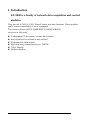
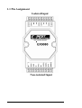
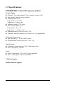
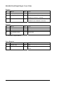
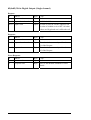
1. ITRODUCTION………………………………….....…….…..….…P3
1.1 Pin Assignment ………………………………….………...…........P4
1.2 Specifications…….…………………………..….………..………..P5
1.3 Block Diagram……..…………………………….………….……..P6
1.4 Application Wiring…………………………………..……………P7
1.4.1 Output Drive SSR or Other Load….………...…………………..P7
1.4.2 Frequency Input…..……………………………………………….P8
1.4.3 Counter Input ……………………………………………………..P8
1.5 Default Setting………………….…………………………….……P9
1.6 Application Notes……………………….…………..……………..P9
1.6.1 Counter/Frequency Input Mode Selection………………………P9
1.6.2 Counter Alarm Mode Selection…………….…………………...P10
1.6.3 Digital Output Application Notes……………….………………P11
1.6.4 Gate Control Setting……………………………….…………….P11
1.6.5 Frequency Input Applications………..…………...……………..P12
1.6.6 Counter Input Applications………..……………….…………....P12
1.7 Tables………………………………………….…………………..P13
2.
Command……………………………...………………………….P14
2.1 %AANNTTCCFF …………………………………...………….P14
2.2 #AAN …………………...……………….……………………….P15
2.3 ~**…………………..…………………………………………….P16
2.4 ~AA0…………...………………………………………………….P17
2.5 ~AA1…………………...…………..……………………………...P18
2.6 ~AA2………………….…………………………………………...P19
2.7 ~AA3ETT……………..……….………………………………….P20
2.8 ~AAO(Data)……...…………………..…………………………...P21
2.9 $AA2…………………...………..………………………………...P22
2.10 $AAF……………………………….……………………………...P23
2.11 $AAM……………………………………………………………...P24
EX9080R User Manual Rev:A.2
1
2.12 ~AAAS……..…………………………….………………………...P25
2.13 $AA6N………………..……………………………………………P26
2.14 $AA7N…………...……….……...………………………………...P27
2.15 $AAA…………....………………….……………………………...P28
2.16 $AAAG ………...…………..……………………………………...P29
2.17 $AAB………...…..……..…………………..……………………...P30
2.18 $AABS……………...……………………………………………...P31
2.19 @AADI……….……...…………..………………………………...P32
2.20 @AADO0D…………...………….………………………………..P33
2.21 @AAEAN……...…..….…..…………….…………………………P34
2.22 @AAEAT………………………………………………………….P35
2.23 @AACA….…...……………………….…………………………..P36
2.24 @AADA…………………………………………...………………P37
2.25 @AADAN.……...…………………………………………………P38
2.26 @AAPA(Data)………………………………………………….…P39
2.27 @AAPA(Data)……....………………………………………….....P40
2.28 @AASA(Data)………...…………………………………………..P41
2.29 @AASA(Data)…….…...……………………………………….…P42
2.30@AARP…..……………..…………………………………P43
2.31@AARP…..………………..…………………………………P44
2.32 @AARA……………….……...…………………………………...P45
2.33 @AARA…………….…….…...…………………………………..P46
2.34 $AA8…………….…….…………….……………………………..P47
2.35 $AA8V…………….…….……………..…………………………..P48
2.36 $AA9(data)………….…….……………………………………....P49
3.
Operations Principle & Application Notes……………..………P50
3.1 INIT*_pin Operation Principle…………………………………P50
3.2 D/O Operation Principle………………………………………...P50
4.
Modbus Quick Start………………...…………….……………...P51
EX9080R User Manual Rev:A.2
2
1. Introduction
EX-9000 is a family of network data acquisition and control
modules.
They provide A/D, D/A, DI/O, Timer/Counter and other functions. These modules
can be remote controlled by a set of commands.
The common features of EX-9080R/RD/EX-9080R-M/RD-M
are given as following:
z
z
z
z
z
z
2 independent 32-bit counter, counter 0& counter1
Input signal can be isolated or non-isolated
Programmable alarm output
Input frequency measurement up to 100KHz
7 SEG Display
Modbus function
EX9080R User Manual Rev:A.2
3
1.1 Pin Assignment
Isolated Input
Non-isolated Input
EX9080R User Manual Rev:A.2
4
1.2 Specifications
EX9080R/RD: Counter/Frequency module.
Counter Input
z Channels: Two independents 32-bit counters, counter 0 &1
z Input signal: Isolated or non-isolated
z Isolation input levels:
Logic level 0: +1V max.
Logic level 1: +3.5V to +30V
z Isolation voltage: 3750 Vrms
z Non-isolation input level:
Logic level 0: 0 to +1V
Logic level 1: +3.5V to +5V
z Maximum count:32-bit (4,294,967,295)
z Alarming: alarm on counter 0 or counter 0 & 1, programmable
Frequency Measurement
z Input frequency: 1 Hz to 100K Hz max.
z Programmable built-in gate time: 1.0/0. 1sec
Digital Output
z 2 channels, open-collector to 30V, 30mA max. load
z Power dissipation: 300mW
Power
z Power requirement: +10V to 30V (non-regulated)
z Power consumption: 2W for EX9080R
7 SEG for Display
Modbus function support
EX9080R User Manual Rev:A.2
5
1.3 Block Diagram
5V
R
Alarm
Output
D+
D-
EEPROM
D/O
O.C
Embedded
Counter_1
Controller
Counter_0
Photo
In0+
Couple
In0-
5V
RS-485
R
5-digit LED (9080RD)
V+
V-
5V
DC
Isolated/Non-isolated input selection
DC 0V
Isolated/Non-isolated gate selection
Photo
In1+
Couple
In1-
5V
R
Photo
Gate0+
Couple
Gate0-
5V
R
Photo
Gate1+
Couple
Gate1-
Isolated Input
Gate0(TTL)
Gate1(TTL)
In0(TTL)
In1(TTL)
Non-Isolated
EX9080R User Manual Rev:A.2
6
1.4 Application Wiring
1.4.1 Output Drive SSR or Other Load
EX9080R
11
12
13
14
15
16
17
18
19
20
Gate1Gate1+
In1In1+
Gate0Gate0+
In0In0+
Do0/Lo
Do/Hi
GND
+VS
Data+
DataInit*
Gate 1
In1
D.Gnd
Gate0
In0
Ext.GND
Ext.24V
RS-485 Data+
RS-485 Data-
10
9
8
7
6
5
4
3
2
1
External Power
External Load
R
+VS
SSR
R2
Note:
z If the external load is resistive load, the 1N4001 can be omitted.
(transistor, lamp, resistor,…….)
z If the external load is inductive load, the 1N4001 can’t be omitted.
(relay, coil,…….)
EX9080R User Manual Rev:A.2
7
AC
1.4.2 Frequency Input
Use $AABS command to select isolated/non-isolated input.
Frequency 1
(Isolated)
Frequency 0
(Isolated)
11
12
13
14
15
16
17
18
19
20
Gate1Gate1+
In1In1+
Gate0Gate0+
In0In0+
Do0/Lo
Do/Hi
GND
+VS
Data+
DataInit*
Gate 1
In1
D.Gnd
Gate0
In0
10
9
8
7
6
5
4
3
2
1
Ext.GND
Ext.24V
RS-485 Data+
RS-485 Data-
GND
+VS
Data+
DataInit*
Gate 1
In1
D.Gnd
Gate0
In0
10
9
8
7
6
5
4
3
2
1
Ext.GND
Ext.24V
RS-485 Data+
RS-485 Data-
Frequency 1
(Non-isolated)
Frequency 0
(Non-isolated)
EX-9080
1.4.3 Counter Input
Counter 1
(Isolated)
Counter 0
(Isolated)
11
12
13
14
15
16
17
18
19
20
Gate1Gate1+
In1In1+
Gate0Gate0+
In0In0+
Do0/Lo
Do/Hi
EX-9080
EX9080R User Manual Rev:A.2
8
Counter 1
(Non-isolated)
Counter 0
(Non-isolated)
1.5 Default Setting
The default setting is given as following:
z
z
z
z
z
z
Address:01
Baud rate: 9600
Checksum disable
Data: 1 start + 8 data+1 stop(no parity)
Type: 50 counter input
Alarm: hi alarm on counter 0 & Counter 1.
1.6 Application Notes
1.6.1 Counter/Frequency Input Mode Selection
The counter/Frequency input can be selected from isolated or non-isolated signal.
The channel 0 & channel 1 can be selected separately. There are 4 different input
mode given as following: These four input modes can be used in EX9080R
Input Mode
Input mode 0
Input mode 1
Input mode 2
Input mode 3
Command
$AAB0
$AAB1
$AAB2
$AAB3
Channel 0
Non-isolated
Isolated
Non-isolated
Isolated
EX9080R User Manual Rev:A.2
Channel 1
Non-isolated
Isolated
Isolated
Non-isolated
9
1.6.2 Counter Alarm Mode Selection
There are two counter alarm mode, alarm mode 0 & alarm mode 1, These two
alarm modes can be used in both of EX9080R.
The alarm mode 0 is designed for two-channel application as following:
Select alarm mode 0: ~AAA0 (for both channels)
z Enable channel 0: @AAEA0
z Disable channel 0: @AADA0
z Set high alarm limit of channel 0: @AAPA(data)
z If (counter 0 >= alarm limit 0) D/O 0 turn ON
z If (counter 0 < alarm limit 0)
D/O 0 turn OFF
z
z
z
z
z
Enable channel 1: @AAEA1
Disable channel 1: @AADA1
Set high alarm limit of channel 1: @AASA(data)
If (counter 1>= alarm limit 1) D/O 1 turn ON
If (counter 1 < alarm limit 1)
D/O 1 turn OFF
The alarm mode 1 is designed for single-channel application as following:
z Select alarm mode 1: ~AAA1(for channel 0 only)
z Enable channel 0: @AAEAT
z Disable channel 0: @AADA
z Clear latch alarm: @AACA
z Set high alarm limit: @AAPA(data)
z Set high-high alarm limit: @AASA(data)
D/O 0
OFF
ON
Counter 0 < high alarm
High alarm <= counter 0 &
counter 0 < high-high alarm
High-high alarm<= counter 0 ON
D/O 1
OFF
OFF
ON
Note: High-high alarm must greater than high-alarm.
EX9080R User Manual Rev:A.2
10
1.6.3 Digital Output Application Notes
The D/O 0 & D/O 1 can be used as D/O or alarm output as following:
z Can be used as D/O in the frequency mode.
z Can be used as D/O in the counter mode & alarm disable
(by @AADA or @AADAN command)
z Can be used as alarm output in the counter mode & alarm enable (by
@AAEAT or @AAEAN command)
D/O 0
Frequency mode
D/O 0
Counter mode & alarm disable
D/O 0
Counter mode & alarm enable (alarm High-alarm on
mode 1, ~AAA1)
counter 0
Counter mode & alarm enable (alarm Alarm on counter
mode 0, ~AAA0 & @AAEA0)
0
Counter mode & alarm enable (alarm D/O 0 or alarm on
mode 0, ~AAA0 & @AAEA1)
counter 0
D/O 1
D/O 1
D/O 1
High-high alarm
on counter 0
D/O 1 or alarm
on counter 1
Alarm on
counter 1
1.6.4 Gate Control Setting
The gate control will be ignored in frequency mode (51).
The gate control is default disable in counter mode (50). The user can use command to
enable/disable the gate control as following:
z $AAA0 = gate input must be low to enable counter.
z $AAA1= gate input must be high to enable counter.
z $AAA2= gate input is ignored. The counter will be always enable.
EX9080R User Manual Rev:A.2
11
1.6.5 Frequency Input Applications
Type=51
$AAB0 = input mode 0
$AAB1 = input mode 1
$AAB2 = input mode 2
$AAB3 = input mode 3
Frequency 0
Non-isolated channel 0
Isolated channel 0
Non-isolated channel 0
Isolated channel 0
Frequency 1
Non-isolated channel 1
Isolated channel 1
Isolated channel 1
Non-isolated channel 1
The steps to measure frequency are given as following:
1. Use $AAB? To select the mode (this command will clear the current frequency
first)
2. Use #AA? To perform frequency measurement.
1.6.6 Counter Input Applications
Type=50
$AAB0 = input mode 0
$AAB1 = input mode 1
$AAB2 = input mode 2
$AAB3 = input mode 3
Counter 0
Non-isolated channel 0
Isolated channel 0
Non-isolated channel 0
Isolated channel 0
Counter 1
Non-isolated channel 1
Isolated channel 1
Isolated channel 1
Non-isolated channel 1
EX9080R User Manual Rev:A.2
12
1.7 Tables
Configuration Code Table: CC
CC
03
04
05
06
07
08
09
0A
Baud Rate
1200BPS
2400BPS
4800BPS
9600BPS
19200BPS
38400BPS
57600BPS
115200BPS
Configuration Code : FF, 2-char (for all)
7
6
5 4 3
2
1
0
Checksum 0
Frequency gate time 0
0=disable
0:0.1 second
1=enable
1:1.0 second
Configuration Code Table: TT
TT
Input Rang
50
Counter
51
Frequency
EX9080R User Manual Rev:A.2
13
0
2. Command
2.1 %AANNTTCCFF
Description: Set Module Configuration
Syntax: %AANNTTCCFF[CHK](cr)
%
delimiter character
AA
address of setting/response module(00 to FF)
NN
new address for setting response module(00 to FF)
TT
new type for setting module
CC
new baudrate for setting module.
It is needed to short the INIT* to ground while change baudrate.
FF
new data format for setting module.
It is needed to short the INIT* to ground to change checksum setting.
Response: Valid Command:
!AA
Invalid Command:
?AA
Example:
Command: %0102500600 Receive: !02
Set module address 01 to 02,Baudrate: 9600bps, counter .
Command: %0202510600 Receive: !02
Change to frequency mode
EX9080R User Manual Rev:A.2
14
2.2 #AAN
Description: Read Digital Input Counter/ frequency from Channel N
Syntex: #AAN(data)[CHK](cr)
#
delimiter character
AA
address of reading/response module(00 to FF)
N
0 = channel 0 of counter /frequency
1 = channel 1 of counter /frequency
Response: Valid Command:
>AA(Data)
Invalid Command:
No response
(Data) 8 character data in HEX format.
Example:
Command: $012 Receive: !01500600
Command: #010 Receive: >0000001E
Counter 0 = 0X1E = 30 (in decimal)
Command: $022 Receive: !02510600
Command: #021 Receive: >0000001E
fequency 1 = 0X1E Hz = 30 Hz (in decimal)
EX9080R User Manual Rev:A.2
15
2.3 ~**
Description: Host OK.
Host send this command to all modules for send the information “Host OK”.
Syntax: ~**[CHK](cr)
~
delimiter character
** command for all modules
Response: No response
Example:
Command: ~** Receive: No response
Send Host OK to all modules.
EX9080R User Manual Rev:A.2
16
2.4 ~AA0
Description: Read Module Status.
Syntax: ~AA0[CHK](cr)
~
delimiter character
AA
address of reading/response module(00 to FF)
0
command for read modules status
Response: Valid Command:
!AASS
Invalid Command:
?AA
SS
Module status, 00=host watchdog timeout status is clear,04=host watchdog
timeout status is set. The status will store into EEPROM and only may
reset by the command ~AA1.
EX9080R User Manual Rev:A.2
17
2.5 ~AA1
Description: Reset Module Status.
Syntax: ~AA1[CHK](cr)
~
delimiter character
AA
address of setting/response module(00 to FF)
1
command for reset modules status
Response: Valid Command:
!AA
Invalid Command:
?AA
EX9080R User Manual Rev:A.2
18
2.6 ~AA2
Description: Read Host Watchdog Timeout Value
Syntax: ~AA2[CHK](cr)
~
delimiter character
AA
address of reading/response module(00 to FF)
2
command for read host watchdog timeout value
Response: Valid Command:
!AASTT
Invalid Command:
?AA
S
TT
Host watchdog enable status, 1=Enable, 0=Disable.
Timeout value in HEX format, Each count is 0.1 second, 01=0.1 second and
FF=25.5 seconds.
EX9080R User Manual Rev:A.2
19
2.7 ~AA3ETT
Description: Set host watchdog Timeout value
Syntax: ~AA3ETT[CHK](cr)
~
delimiter character
AA
address of setting/response module(00 to FF)
3
command for set host watchdog timeout value
E
1=Enable/0=Disable host watchdog
TT
timeout value, from 01 to FF, each for 0.1 second
Response: Valid Command:
!AA
Invalid Command:
?AA
Example:
Command: ~010
Receive: !0100
Read address 01 modules status, return host watchdog timeout status is clear.
Command: ~013164
Receive: !01
Set address 01 host watchdog timeout value 10.0 seconds and enable host watchdog,
return success.
Command: ~012
Receive: !01164
Read address 01 host watchdog timeout value, return that host watchdog is enabled,
and time interval is 10.0 seconds.
Command: ~**
No response
Reset the host watchdog timer.
Wait for about 10 seconds and don’t send command ~**, the LED of module will go
to flash. The flash LED indicates the host watchdog timeout status is set.
Command: ~010
Receive: !0104
Read address 01 module status, return host watchdog timeout status is set.
Command: ~012
Receive: !01064
Read address 01 host watchdog timeout value, return that host watchdog is disabled,
and time intervals is 10.0 seconds.
Command: ~011
Receive: !01
Reset address 01 host watchdog timeout status, return success and the LED of this
module stop flash.
Command: ~010
Read address 01 module status, return host watchdog timeout status is clear.
EX9080R User Manual Rev:A.2
20
2.8 ~AAO(Data)
Description: Set Module Name
Syntax: ~AAO(Data)[CHK](cr)
~
delimiter character
AA
address of setting/response module(00 to FF)
O
command for set module name
(Data) new name for module, max 6 characters
Response: Valid Command:
!AA
Invalid Command:
?AA
Example:
Command: ~01O9050 Receive: !01
Set address 01 module name 9050, return success.
Command: $01M Receive: !019050
Read address 01 module name, return name 9050
EX9080R User Manual Rev:A.2
21
2.9 $AA2
Description: Read Configuration
Syntax: $AA2[CHK](cr)
$
delimiter character
AA address of reading/response module(00 to FF)
2
command for read configuration
Response: Valid Command:
!AATTCCFF
Invalid Command:
?AA
TT
type code of module
CC
baudrate code of module
FF
data format of module
Example:
Command: $012 Receive: !01500600
Read address 01 status, return counter mode, 9600bps, no checksum
Command: $022 Receive: !02510700
Read address 02 status, return frequency, 19200bps, no checksum
EX9080R User Manual Rev:A.2
22
2.10 $AAF
Description: Read Firmware Version
Syntax: $AAF[CHK](cr)
$
delimiter character
AA address of reading/response module(00 to FF)
F
command for read firmware version
Response: Valid Command:
!AA(Data)
Invalid Command:
?AA
(Data)
firmware version of module
Example:
Command: $01F Receive: !01R1.4
Read address 01 firmware version, return version R1.4.
Command: $01F Receive: !01A1.4
Read address 01 firmware version, return version A1.4.
EX9080R User Manual Rev:A.2
23
2.11 $AAM
Description: Read Module Name
Syntax: $AAM[CHK](cr)
$
delimiter character
AA address of reading/response module(00 to FF)
M
command for read module name
Response: Valid Command:
!AA(Data)
Invalid Command:
?AA
(Data)
Name of module
Example:
Command: $01M Receive: !019021
Read address 01 module name, return name 9021.
Command: $03M Receive: !029024
Read address 03 module name, return name 9024
EX9080R User Manual Rev:A.2
24
2.12 ~AAAS
Description: Set counter alarm mode.
Syntax: ~AAAS[CHK](cr)
~
delimiter character
AA address of setting/response module(00 to FF)
S
0 = alarm mode 0.
1 = alarm mode 1.
Response: Valid Command:
!AA
Invalid Command:
?AA
Example:
Command: ~01A0 Receive: !01
Set alarm mode = 0
Command: ~02A1 Receive: !02
Set alarm mode = 1
EX9080R User Manual Rev:A.2
25
2.13 $AA6N
Description: Reset counter 0 or counter 1 to the preset value & clear the overflow
flag.
Syntax: $AA6N[CHK](cr)
$
delimiter character
AA address of setting/response module(00 to FF)
N
0 = counter 0
1 = counter 1
Response: Valid Command:
!AA
Invalid Command:
?AA
Example:
Command: @01G0 Receive: !0100000000
Preset value = 0
Command: $0160 Receive: !01
Reset counter 0 to preset value 0
Command: @01G1 Receive: !010000ABCD
Preset value = 0xABCD
Command: $0161 Receive: !01
Reset counter 1 to preset value 0xABCD
EX9080R User Manual Rev:A.2
26
2.14 $AA7N
Description: Read the overflow flag of counter. The user can use $AA6S command to
reset counter & clear overflow flag.
Syntax: $AA7N[CHK](cr)
$
delimiter character
AA
address of reading/response module (00 to FF)
N
0 = counter 0
1 = counter 1
Response: Valid Command:
!AAS
Invalid Command:
?AA
S
0 = no overflow
1 = is overflow
Example:
Command: $0170 Receive: !011
Counter 0 is overflow.
Command: $0160 Receive: !01
Clear the overflow flag.
Command: $0171 Receive: !010
Counter 1 is OK.
EX9080R User Manual Rev:A.2
27
2.15 $AAA
Description: Read gate control mode.
Syntax: $AAA[CHK](cr)
$
delimiter character
AA address of reading/response module (00 to FF)
Response: Valid Command:
!AAG
Invalid Command:
?AA
G
0 = gate is low active.
1 = gate is high active.
2 = gate is disable
Example
Command: $01A Receive: !010
Gate is low active.
Command: $02A Receive: !021
Gate is high active
Command: $03A Receive: !032
Gate is disable (always active)
EX9080R User Manual Rev:A.2
28
2.16 $AAAG
Description: Set gate control mode.
Syntax: $AAAG[CHK](cr)
$
delimiter character
AA address of setting/response module(00 to FF)
G
0 = gate is low active.
1 = gate is high active.
2 = gate is disable.
Response: Valid Command:
!AA
Invalid Command:
?AA
Example:
Command: $01A0 Receive: !01
Gate is low active.
Command: $02A1 Receive: !02
Gate is high active.
Command: $03A2
Receive: !03
Gate is disable (always active)
EX9080R User Manual Rev:A.2
29
2.17 $AAB
Description: Read input mod.
Syntax: $AAB[CHK](cr)
$
delimiter character
AA address of reading/response module (00 to FF)
Response: Valid Command:
!AAS
Invalid Command:
?AA
S
0= channel 0 is non-isolated, channel 1 is non-isolated.
1= channel 0 is isolated, channel 1 is isolated.
2= channel 0 is non-isolated, channel 1 is isolated.
3= channel 0 is isolated, channel 1 is non-isolated.
Example:
Command: $01B Receive: !010
Counter/frequency channel 0 is non-isolated, channel 1 is non-isolated
Command: $02B Receive: !021
Counter/frequency channel 0 is isolated, channel 1 is isolated
Command: $03B Receive:!032
Counter/frequency channel 0 is non-isolated, channel 1 is isolated
EX9080R User Manual Rev:A.2
30
2.18 $AABS
Description: Set input mode.
Syntax: $AABS[CHK](cr)
$
delimiter character
AA address of Setting/response module (00 to FF)
S
0= channel 0 is non-isolated, channel 1 is non-isolated.
1= channel 0 is isolated, channel 1 is isolated.
2= channel 0 is non-isolated, channel 1 is isolated.
3= channel 0 is isolated, channel 1 is non-isolated.
Response: Valid Command:
!AA
Invalid Command:
?AA
Example:
Command: $01B0 Receive: !01
Counter/frequency channel 0 is non-isolated, channel 1 is non-isolated
Command: $02B1 Receive: !02
Counter/frequency channel 0 is isolated, channel 1 is isolated
Command: $03B2 Receive: !03
Counter/frequency channel 0 is non-isolated, channel 1 is isolated
EX9080R User Manual Rev:A.2
31
2.19 @AADI
Description: Read D/O and Alarm Status.
Syntax: @AADI[CHK](cr)
@
delimiter character
AA
address of reading/response module(00 to FF)
DI
command for reading digital output and alarm status
Response: Valid Command:
!AAS0D00
Invalid Command:
?AA
D
0 = D/O0 = D/O1= OFF
1 = D/O0 = ON, D/O1 = OFF
2 = D/O0 = OFF, D/O1 = ON
3 = D/O0 = D/O1 = ON
S(alarm mode 0)0 = counter 0 alarm = disable, counter 1 alarm = disable.
1 = counter 0 alarm = enable, counter 1 alarm = disable.
2 = counter 0 alarm = disable, counter 1 alarm = enable.
3 = counter 0 alarm = enable, counter 1 alarm = enable.
S(alarm mode 1)0 = counter 0 alarm = disable.
1 = counter 0 alarm = enable & MOMENTARY mode.
2 = counter 0 alarm = enable & LATCH mode.
Example:
Command: @01DI Receive: !0100000
Alarm disable. D/O0= D/O1=OFF.
Command: @02DI
Receive: !0230100
Alarm enable. D/O0=ON, D/O1=OFF.
EX9080R User Manual Rev:A.2
32
2.20
@AADO0D
Description: Set digital output.
Syntax: @AADO0D[CHK](cr)
@
delimiter character
AA
address of Setting/response module (00 to FF)
D
0=DO0 off, DO1 off,
1=DO0 on, DO1 off,
2=DO0 off, DO1 on,
3=DO0 on, DO1 on.
Response: Valid Command:
!AA
Invalid Command:
?AA
Alarm is enable:
?AA
Example:
Command: @01DO00
Receive: !01
Turn all D/O OFF.
Command: @02DO01 Receive: !02
Turn D/O 0 ON, Turn D/O 1 OFF.
NOTE: If the alarm is enable, the D/O 0 & D/O 1 will be always controlled by
module. Therefore the following D/O commands will be ignored.
1. Power-on value is changed to hi/lo condition immediately
2. The @AADO0D command is ignored.
EX9080R User Manual Rev:A.2
33
2.21 @AAEAN
Description: Enable counter alarm (for alarm-mode 0).
Syntax: @AAEAN[CHK](cr)
@
delimiter character
AA
address of setting/response module (00 to FF)
N
0 = enable counter 0
1 = enable counter 1
Response: Valid Command:
!AASS
Invalid Command:
?AA
Example:
Command: @01EA0
Receive: !01
Enable counter 0
Command: @01EA1
Receive: !02
Enable counter 1
EX9080R User Manual Rev:A.2
34
2.22 @AAEAT
Description: Enable counter alarm (for alarm-mode 1).
Syntax: @AAEAT[CHK](cr)
@
delimiter character
AA
address of setting/response module(00 to FF)
T
M = momentary alarm
L = latch alarm
Response: Valid Command:
!AA
Invalid Command:
?AA
Example:
Command: @01EAL
Receive: !01
Latch alarm
Command: @02EAM
Receive: !02
Momentary alarm.
NOTE: If the alarm is enable, the D/O 0 & D/O 1 will be always controlled by
module. Therefore the following D/O commands will be ignored.
1.Power-on value is changed to hi/lo condition immediately
2.The @AADO0D command is ignored.
EX9080R User Manual Rev:A.2
35
2.23
@AACA
Description: Clear latch alarm (for alarm-mode 1)
Syntax: @AACA[CHK](cr)
@
delimiter character
AA
address of setting/response module(00 to FF)
Response: Valid Command:
!AA
Invalid Command:
?AA
Example:
Command: @01CA
Receive: !01
Clear latch alarm.
Command: @02CA
Receive: !02
Clear latch alarm.
EX9080R User Manual Rev:A.2
36
2.24
@AADA
Description: Disable alarm(for alarm-mode 1)
Syntax: @AADA[CHK](cr)
@
delimiter character
AA
address of setting/response module(00 to FF)
Response: Valid Command:
!AA
Invalid Command:
?AA
Example:
Command: @01DA
Disable alarm
Command: @02DA
Disable alarm
Receive: !01
Receive: !02
EX9080R User Manual Rev:A.2
37
2.25 @AADAN
Description: Disable alarm (for alarm-mode 0)
Syntax: @AADAN[CHK](cr)
@
delimiter character
AA
address of setting/response module (00 to FF)
N
0= disable counter 0
1 = disable counter 1
Response: Valid Command:
!AA
Invalid Command:
?AA
Example:
Command: @01DA0
Receive: !01
Disable counter 0 alarm.
Command: @02DA1
Receive: !02
Disable counter 1 alarm.
EX9080R User Manual Rev:A.2
38
2.26
@AAPA(data)
Description: Set alarm limit of counter 0 (for alarm-mode 0)
Syntax: @AAPA(data)[CHK](cr)
@
delimiter character
AA
address of setting/response module(00 to FF)
(Data)
8 character data in HEX format.
Response: Valid Command:
!AA
Invalid Command:
?AA
Example:
Command: @01PAFFFF0000
Receive: !01
The alarm limit of counter 0 is FFFF0000.
Command: @02PA0000FFFF
Receive: !02
The alarm limit of counter 0 is 0000FFFF.
EX9080R User Manual Rev:A.2
39
2.27 @AAPA(data)
Description: Set Hi-alarm limit of counter 0 (for alarm-mode 1)
Syntax: @AAPA[CHK](cr)
@
delimiter character
AA
address of setting/response module(00 to FF)
(data)
8-character HEX value.
Response: Valid Command:
!AA
Invalid Command:
?AA
Example:
Command: @01PAFFFF0000
Receive: !01
The Hi-alarm limit of counter 0 is FFFF0000.
Command: @02PA0000FFFF
Receive: !02
The Hi-alarm limit of counter 0 is 0000FFFF.
EX9080R User Manual Rev:A.2
40
2.28 @AASA(data)
Description: Set alarm limit of counter-1(for alarm-mode 0)
Syntax: @AASA[CHK](cr)
@
delimiter character
AA
address of setting/response module (00 to FF)
(data) 8-character HEX value.
Response: Valid Command:
!AA
Invalid Command:
?AA
Example:
Command: @01SAFFFF0000 Receive: !01
The alarm limit of counter 1 is FFFF0000.
Command: @02SA0000FFFF Receive: !02
The alarm limit of counter 1 is 0000FFFF.
EX9080R User Manual Rev:A.2
41
2.29 @AASA(data)
Description: Set Hi-Hi-alarm limit of counter 1(for alarm-mode 1)
Syntax: @AASA[CHK](cr)
@
delimiter character
AA
address of setting/response module (00 to FF)
(data) 8-character HEX value.
Response: Valid Command:
!AA
Invalid Command:
?AA
Example:
Command: @01SAFFFF0000 Receive: !01
The Hi-Hi-alarm limit of counter 1 is FFFF0000.
Command: @02SA0000FFFF Receive: !02
The Hi-Hi-alarm limit of counter 1 is 0000FFFF.
EX9080R User Manual Rev:A.2
42
2.30 @AARP
Description: Read alarm limit of counter 0 (for alarm-mode 0)
Syntax: @AARP[CHK](cr)
@
delimiter character
AA
address of reading/response module(00 to FF)
Response: Valid Command:
!AA(Data)
Invalid Command:
?AA
(Data)
8-character HEX value.
Example:
Command: @01RP
Receive: !01FFFF0000.
The alarm limit of counter 0 is FFFF0000.
Command: @02RP
Receive: !020000FFFF.
The alarm limit of counter 0 is 0000FFFF.
EX9080R User Manual Rev:A.2
43
2.31 @AARP
Description: Read Hi-alarm limit of counter 0 (for alarm-mode 1)
Syntax: @AARP[CHK](cr)
@
delimiter character
AA
address of reading/response module(00 to FF)
Response: Valid Command:
!AA(Data)
Invalid Command:
?AA
(Data)
8-character HEX value.
Example:
Command: @01RP
Receive: !01FFFF0000.
The Hi-alarm limit of counter 0 is FFFF0000.
Command: @02RP
Receive: !020000FFFF.
The Hi-alarm limit of counter 0 is 0000FFFF.
EX9080R User Manual Rev:A.2
44
2.32 @AARA
Description: Read alarm limit of counter 1 (for alarm-mode 0)
Syntax: @AARA[CHK](cr)
@
delimiter character
AA
address of readiing/response module (00 to FF)
Response: Valid Command:
!AA (data)
Invalid Command:
?AA
(data)
8-character HEX value.
Example:
Command: @01RA Receive: !01FFFF0000
The alarm limit of counter 1 is FFFF0000.
Command: @02RA Receive: !020000FFFF.
The alarm limit of counter 1 is 0000FFFF.
EX9080R User Manual Rev:A.2
45
2.33 @AARA
Description: Read Hi-Hi-alarm limit of counter 1 (for alarm-mode 1)
Syntax: @AARA[CHK](cr)
@
delimiter character
AA
address of readting/response module (00 to FF)
Response: Valid Command:
!AA (data)
Invalid Command:
?AA
(data)
8-character HEX value.
Example:
Command: @01RA Receive: !01FFFF0000
The Hi-Hi-alarm limit of counter 1 is FFFF0000.
Command: @02RA Receive: !020000FFFF.
The Hi-Hi-alarm limit of counter 1 is 0000FFFF.
EX9080R User Manual Rev:A.2
46
2.34 $AA8
Description: Read the LED configuration.
Syntax: $AA8[CHK](cr)
$
delimiter character
AA address of setting/response module(00 to FF)
8
command for read the LED configuration
Response: Valid Command:
!AAS
Invalid Command:
?AA
S
0 = show counter/frequency channel 0
1 = show counter/frequency channel 1
2 = Host control
Example:
Command: $018
Receive: !010
Address 01 module’s LED show the value of channel 0.
Command: $038
Receive: !032
Host control the Address 03 module’s LED.
Command: $048
Receive: !041
Address 04 module’s LED show the value of channel 1.
EX9080R User Manual Rev:A.2
47
2.35 $AA8V
Description: Select LED configuration.
Syntax: $AA8V[CHK](cr)
$
delimiter character
AA address of setting/response module(00 to FF)
V
0 = LED show counter/frequency channel 0
1 = LED show counter/frequency channel 1
2 =Host control LED
Response: Valid Command:
!AA
Invalid Command:
?AA
Example:
Command: $0180
Receive: !01
Select address 01 module’s LED show the value of channel 0.
Command: $0382
Receive: !03
Select host control the Address 03 module’s LED.
EX9080R User Manual Rev:A.2
48
2.36 $AA9(data)
Description: Send data to LED display.
Syntax: $AA9(data)[CHK](cr)
$
delimiter character
AA address of setting/response module(00 to FF)
9
command for send data to LED display
(data) 0 = 5 decimal digit + 1 decimal point
min: 0.0000 ~ max: 99999.
Response: Valid Command:
!AA
Invalid Command:
?AA
Example:
Command: $0188888.
Receive: !01
Set address 01 module’s LED display = 88888.
Command: $0312.345
Receive: !03
Set address 03 module’s LED display = 12.345
Note: Before Send data to LED display of EX-9080R/RD, user must make sure the
LED configuration is select to Host Control (P.2.34/2.35)
EX9080R User Manual Rev:A.2
49
3. Operations Principle & Application Notes
3.1 INIT*_pin Operation Principle
All EX9000 modules contain an EEPROM to store configuration information.
Therefore the user is difficult to find out the status of the EX9000 module. The user
can connect the INIT*_pin to GND_pin and power on the module. The EX9000
modules will go to the factory default setting without changing the EEPROM data.
The factory default setting is given as following:
Address = 00
Baud rate = 9600
Checksum = DISABLE
Data format = 1 start + 8 data bits + 1 stop bit
If the user disconnect the INIT*_pin and GND_pin, the EX9000 module will be
auto configured according to the EEPROM data. The user is easy to find the
EEPROM configuration data in the default setting. The steps are shown as following:
Step 1: Power off and connect INIT*_pin to GND_Pin.
Step 2: Power on.
Step 3: Send command string $002 (0x0D) to the module, the module will return back
the EEPROM data.
Step 4: Record the EEPROM data of this EX9000 module.
Step 5: Power off and disconnect INIT*_Pin and GND_Pin.
Step 6: Power on.
3.2 D/O Operation Principle
1. The D/O output of EX9080R modules will be turn OFF after first power on.
2. The D/O output will be changed to the desired state if the @AADO command is
received. Then all these D/O will keep in the same states until next @AADO
command.
3. If the host watchdog is active all the D/O will not change and the module status is
set to 04. If the host computer send out @AADO to those modules now, those
modules will ignore this command and return ! as warning information. The host
can use ~AA1. command to clear the module status to 0 ,than the EX9080R
module will accept the @AADO again.
4. If the D/O output is configured as alarm output, the module will control the
ON/OFF state automatically. Therefore the “@AADO” command will be ignored
in this condition.
EX9080R User Manual Rev:A.2
50
4.EX9080R-M Quick Start
1. The default setting is MODBUS mode after Power On.
2. Using INIT pin to contact with GND pin then Power On will enter Normal
mode.
3. Command: $00R0 is set EX9080R-M to Normal mode after Repower On. On
normal mode, user can set other setting like address, Baudrate, ….. (Please
check the EX9000 user manual).
4. Command: $AAR1 is set to MODBUS mode after Repower On.
The Modbus protocol was originally developed for Modicon controllers by
Modicon Inc. Detailed information can be found at
http://www.modicon.com/techpubs/toc7.html. Visit http://www.modbus.orq to
find more valuable information.
9000M series modules support the Modbus RTU protocol. The communication
Baud Rates range from 1200bps to 115200bps. The parity, data bits and stop bits
are fixed as no parity, 8 data bits and 1stop bit. The following Modbus functions
are supported.
EX9080R User Manual Rev:A.2
51
01(0x01) Read Digital Output Value
Request
00
Address
1 Byte
1-247
01
Function code
1 Byte
0x01
02~03 Starting channel
2 Bytes 0x0010~0x0011 for DO readback value
04~05 Input/Output channel
numbers
2 Bytes 0x0001~0x0002
Response
00
Address
1 Byte
1-247
01
Function code
1 Byte
0x01
02
Byte count
1 Byte
1
03
Input/Output channel
readback value
1 Byte
0x00~0x03
A bit corresponds to a channel. When the
bit is 1 it denotes that the value of the
channel that was set is ON. if the bit is 0 it
denotes that the value of the channel that
was set is OFF.
Error Response
00
Address
1 Byte
1-247
01
Function code
1 Byte
0x81
02
Exception code
1 Byte
Refer to the Modbus standard for more
details.
EX9080R User Manual Rev:A.2
52
02(0x02) Read Digital Output Value
Request
00
Address
1 Byte
1-247
01
Function code
1 Byte
0x02
02~03 Starting channel
2 Bytes 0x0010~0x0011 for DO readback value
04~05 Input/Output channel
numbers
2 Bytes 0x0001~0x0002
Response
00
Address
1 Byte
1-247
01
Function code
1 Byte
0x02
02
Byte count
1 Byte
1
03
Input/Output channel
readback value
1 Byte
0x00~0x03
A bit corresponds to a channel. When the
bit is 1 it denotes that the value of the
channel that was Input response. if the bit
is 0 it denotes that the value of the channel
that was no Input response .
Error Response
00
Address
1 Byte
1-247
01
Function code
1 Byte
0x82
02
Exception code
1 Byte
Refer to the Modbus standard for more
details.
EX9080R User Manual Rev:A.2
53
03(0x03) Read Digital Input Count Value
Request
00
Address
1 Byte
1-247
01
Function code
1 Byte
0x03
02~03 Starting channel
2 Bytes 0x0000 for channel 0 starting
0x0002 for channel 1 starting
04~05 Input channel numbers
2 Bytes 0x0002 for one channel (2 words)
0x0004 for two channels (4 words)
Response
00
Address
1 Byte
1-247
01
Function code
1 Byte
0x03
02
Byte count
1 Byte
N* x 4
03~
Input channel count
value
N* x 4
Byte
Return data
N*=Number of input channels
Error Response
00
Address
1 Byte
1-247
01
Function code
1 Byte
0x83
02
Exception code
1 Byte
Refer to the Modbus standard for more
details.
EX9080R User Manual Rev:A.2
54
04(0x04) Read Digital Input Count Value
Request
00
Address
1 Byte
1-247
01
Function code
1 Byte
0x04
02~03 Starting channel
2 Bytes 0x0000 for channel 0 starting
0x0002 for channel 1 starting
04~05 Input channel numbers
2 Bytes 0x0002 for one channel (2 words)
0x0004 for two channels (4 words)
Response
00
Address
1 Byte
1-247
01
Function code
1 Byte
0x04
02
Byte count
1 Byte
N* x 4
03~
Input channel count
value
N* x 4
Byte
Return data
N*=Number of input channels
Error Response
00
Address
1 Byte
1-247
01
Function code
1 Byte
0x84
02
Exception code
1 Byte
Refer to the Modbus standard for more
details.
EX9080R User Manual Rev:A.2
55
05(0x05) Write Digital Output (Single channel)
Request
00
Address
1 Byte
1-247
01
Function code
1 Byte
0x05
02~03 Output channel number
2 Bytes 0x0010~0x0011
04~05 Output value
2 Bytes A value of 0xFF00 sets the output to ON.
A value of 0x0000 set it to OFF. All other
values are illegal and won’t affect the coil.
Response
00
Address
1 Byte
1-247
01
Function code
1 Byte
0x05
02~03 Output channel numbers 2 Bytes The value is the same as byte 02 and
03 of the Request
04~05 Output value
2 Bytes The value is the same as byte 04 and
05 of the Request
Error Response
00
Address
1 Byte
1-247
01
Function code
1 Byte
0x85
02
Exception code
1 Byte
Refer to the Modbus standard for more
details.
EX9080R User Manual Rev:A.2
56
06(0x06) Clear Digital Input Count Value
Request
00
Address
1 Byte
1-247
01
Function code
1 Byte
0x06
02~03 Input channel number
2 Bytes 0x0000 for channel 0
0x0002 for channel 1
04~05 Clear channel count
2 Bytes 0x0000 for clear
Response
00
Address
1 Byte
1-247
01
Function code
1 Byte
0x06
1 Byte
The value is the same as byte 02 ~05 of
the Request
02~05 Byte count
Error Response
00
Address
1 Byte
1-247
01
Function code
1 Byte
0x86
02
Exception code
1 Byte
Refer to the Modbus standard for more
details.
EX9080R User Manual Rev:A.2
57
15(0x0F) Write Digital Output
Request
00
Address
1 Byte
1-247
01
Function code
1 Byte
0x0F
02~03 Starting channel
2 Bytes 0x0010~0x0011
04~05 Output channel numbers 2 Bytes 0x0001~0x0002
06
Byte count
1 Byte
1
07
Output value
1 Byte
0x00~0x03
A bit corresponds to a channel. When the
bit is 1 it denotes that the value of the
channel that was set is ON. if the bit is 0 it
denotes that the value of the channel that
was set is OFF.
Response
00
Address
1 Byte
1-247
01
Function code
1 Byte
0x0F
02~03 Starting channel
2 Bytes The value is the same as byte 02 and
03 of the Request
04~05 Output channel numbers 2 Bytes The value is the same as byte 04 and
05 of the Request
Error Response
00
Address
1 Byte
1-247
01
Function code
1 Byte
0x8F
02
Exception code
1 Byte
Refer to the Modbus standard for more
details.
EX9080R User Manual Rev:A.2
58
Modbus Mapping Table:
9080R-M/9080RD-M
Address
Hex
Channel
Content
Attribute
Note
40001~40002 0H~1H
0
Analog input Value
Read/Write
Function code 6 clear CH0
01 06 00 00 00 00 crch crcl
40003~40004 2H~3H
1
Analog input Value
Read/Write
Function code 6 clear CH1
01 06 00 02 00 00 crch crcl
0017
10H
0
Digital Output Value
Read/Write
0018
11H
1
Digital Output Value
Read/Write
EX9080R User Manual Rev:A.2
59