1
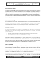
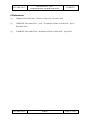
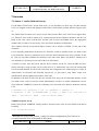
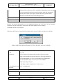
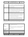
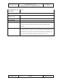
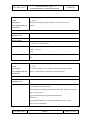
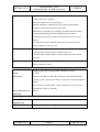
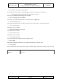
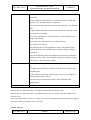
IST-2000-25187
Deliverable D4.5 – part 2
Evaluation of Phase Two Field Trials: Part 2
TORRENT
Project Number:
IST-2000-25187
Project Title:
TORRENT
Deliverable Security*:
PU
CEC Deliverable Number:
D4.5 – part 2
Project Document Number:
01-033-v001-wp4-PU-R-d4.5.2
Contractual Date of Delivery to the CEC:
16.02.2004
Actual Date of Delivery to the CEC:
Title of Deliverable:
Evaluation of Phase Two Field Trials: Part 2
Work package contributing to the Deliverable:
WP4
Type of Deliverable**:
R
Author:
Isabel Borges
Contributors:
M.Potts, B. Voegtli (MCLab); R. Tolstra, H.
Singer (tesion); W. Payer (UST); I.
Mountzouris (Intracom); A. Costoloni
(Flextel); P. Hammer (QMUL); J. Ronan
(WIT); I. Borges, C. Rodrigues (PTIN)
* Security:
PU – Public, PP - Restricted to other programme participants (including the Commission Services)
RE - Restricted to a group specified by the consortium (including the Commission Services)
CO - Confidential, only for members of the consortium (including the Commission Services)
** Type:
R - Report, P - Prototype, D - Demonstrator, O - Other
Abstract: This deliverable is concerned with the validation of the key functionalities of the second phase of
the TORRENT system. After the delivery of D4.5 part 1, in which ADSL and CATV scenarios, access
convergence and user aspects were investigated, this document reports the results of tesion core
interconnectivity trial.
Keywords: Field trial, evolution, results, testing, evaluation
IST-2000-25187
PUBLIC
Page 1 of 54
IST-2000-25187
Deliverable D4.5 – part 2
Evaluation of Phase Two Field Trials: Part 2
TORRENT
© This Deliverable is Copyright of the
TORRENT Consortium
IST-2000-25187
whose partners are:
Queen Mary and Westfield College (UK)
Portugal Telecom Inovação SA (Portugal)
Temagon (Greece)
Telenor AS (Norway)
tesion Communikationsnetze Südwest GmbH (Germany)
Flextel SPA (Italy)
Intracom SA (Greece)
MCLAB GmbH (Switzerland)
Universität Stuttgart (Germany)
Waterford Institute of Technology (Ireland)
IST-2000-25187
PUBLIC
Page 2 of 54
IST-2000-25187
Deliverable D4.5 – part 2
Evaluation of Phase Two Field Trials: Part 2
TORRENT
Executive Summary
This deliverable presents the results and the analysis of results of the phase II - part 2 field trial,
namely the UST/MCLab/tesion trial. Chapter one and chapter two will give an introduction and will
identify the objectives related with this document.
Third chapter focus on the description, configuration and lessons learnt of field trial. The approach
used consisted on testing the functionalities of the system, as much as possible as described at D4.4,
“Definition of phase II field trials”. The phase II field trial-part 2 had run in the deployed
infrastructure connecting MCLab and University of Stuttgart through tesion IP backbone. The results
coming from the tesion trial had been inputted to WP2, WP3 contributed to some improvements and
to WP5 (Exploitation and Dissemination).
Finally, in chapter four, are stated the main conclusions resulting from this work.
At the annex all the tests and results are described.
IST-2000-25187
PUBLIC
Page 3 of 54
IST-2000-25187
Deliverable D4.5 – part 2
Evaluation of Phase Two Field Trials: Part 2
TORRENT
Table of Contents
Executive Summary ............................................................................................................ 3
1 Introduction ...................................................................................................................... 5
2 Objectives ......................................................................................................................... 5
3 Description of Field Trial.................................................................................................. 5
3.1 tesion Field Trial ........................................................................................... 5
3.1.1 Trial Description - testbed configuration ................................................... 5
Core networks ................................................................................................ 5
3.1.2 Trial results .......................................................................................... 8
3.1.3 Lessons learnt from tesion field trial ........................................................ 8
Flow based priority queuing............................................................................. 10
Core network monitoring ................................................................................. 10
Bandwidth accounting...................................................................................... 10
Failover functionality ....................................................................................... 10
4 Conclusions.................................................................................................................... 13
5 Abbreviations ................................................................................................................. 14
6 References...................................................................................................................... 15
7 Annexes .......................................................................................................................... 16
7.1 Annex 1 - tesion field trial set-up .................................................................. 16
7.2 Annex 2 - List of tests and results ................................................................. 18
7.3 Annex 3 – MCLab/tesion Configurations ......................................................... 53
IST-2000-25187
PUBLIC
Page 4 of 54
IST-2000-25187
Deliverable D4.5 – part 2
Evaluation of Phase Two Field Trials: Part 2
TORRENT
1 Introduction
The phase II of the Torrent project runs from February 2003 till February 2004 and covers five
different countries. Due to delays occurred at tesion trial in the new software releases and E1
cards integration, this trial was delayed till the end of December 2003 to allow the
accomplishment of the testing plan [1]. This is the main reason for having two deliverables
with the evaluation of phase II field trials. The first one named D4.5 part 1 contains the main
results of Temagon, Telenor and PTIN field trials results. [2]
This document will report the tesion field trial evaluation and the results of the set of tests that
were performed. Those tests have been described as well as the definition of each of the phase
II trials at D4.4, “Definition of Phase II trials”, [3].
2 Objectives
The main objective of this deliverable is to present the final results of the tests that were specified in
deliverable D4.4, “Definition of Phase II Field Trials” [3], and consequently the evaluation of the
TORRENT concept: “To build a test-bed for residential multi-service access networks that will allow
the project to demonstrate the benefit of intelligent control, both for the customer and the network
operators”. The results presented here are very important since they will allow verifying the
interconnection of two LAPs networks through an IP backbone connecting two countries, with the
Torrent system selecting the most appropriate core network based on User Preferences.
3 Description of Field Trial
This chapter will describe the phase II tesion field trial configuration.
3.1 tesion Field Trial
3.1.1
Trial Description - testbed configuration
Core networks
The LAP’s will be based in Stuttgart (IND) and Basel (MCLab) and there will be dedicated accesses
to different types of networks. This enables the LAP to select and access the most suitable network
depending on the requested application.
In this way the following interconnections will be realised:
•
IP over MPLS
•
IP tunnelled or via VPN
•
SDH
IST-2000-25187
PUBLIC
Page 5 of 54
IST-2000-25187
Deliverable D4.5 – part 2
Evaluation of Phase Two Field Trials: Part 2
TORRENT
Since tesion is a full-service provider, there is a choice between voice (switch), data and Internet
services. The network technologies integrated are ATM, IP, MPLS, SDH and DWDM.
This resulted in a network routing as shown below. This enables the testing using IPv4.
Figure 1: Network routing
One of the items that have gained importance was the implementation of IPv6 instead of IPv4. This of
course had also an impact on the field trial between Basel and Stuttgart.
During the field trial there were dedicated core routers in Karlsruhe and Stuttgart.
The following interconnections were performed:
•
IP over MPLS
The beta-software takes the IPv6 packet and puts a MPLS header on top of this packet.
Then it is transferred through the MPLS core network. At the destination this header is removed and
the IPv6 packet is transported further to its final destination.
•
IP tunnelled
IST-2000-25187
PUBLIC
Page 6 of 54
IST-2000-25187
Deliverable D4.5 – part 2
Evaluation of Phase Two Field Trials: Part 2
TORRENT
Originally (IPv4) an IP VPN was planned. The disadvantage for the available IPv6 MPLS SW is that
the IPv6 VPN is not available yet. In order to simulate this, the interconnection will be simulated by
tunnelling through the network.
•
SDH
This is in fact a leased line and can be considered as a very fast network with optimal QoS.
Figure 2: tesion configuration
Figure 2 and Figure 3 shows the set-up at MCLab.
Figure 3: ADSL Modem Configuration
IST-2000-25187
PUBLIC
Page 7 of 54
IST-2000-25187
3.1.2
Deliverable D4.5 – part 2
Evaluation of Phase Two Field Trials: Part 2
TORRENT
Trial results
The main features of this field trial were to test the capabilities of the combined RG and LAP in
connection with different types of networks and also, the interconnectivity between LAPs.
The aspects and features were:
1. The ability of the RG to be connected to different networks
2. The ability of interworking between RG and LAP and LAP to LAP
3. The ability of the user to select the appropriate network (QoS)
4. Ability to provide system status information to the RG and LAP
5. Ability to suit network operator requirements
The results of the tests performed are included in annex 7.1 and 5.2.
3.1.3
Lessons learnt from tesion field trial
Apart from the driver issues that occurred on the E1 cards in the LAP and that were finally solved by
downgrading the driver software and reconfiguration of the Network access into Framed mode, there
have been TCP transmission errors in the direction from Stuttgart to Basel. For these errors, it is
unlikely that they are related to a software error in either one of the LAP’s because they occurred only
on the first two E1 lines. The third E1 connection did not produce any TCP errors, although it used the
same set-up. The only difference was that the third connection was a direct one (SDH), without any
intermediate IP routers. Therefore it was concluded, that a faulty or mis-configured intermediary
device was disturbing the traffic between Stuttgart and Basel on the first two E1 connections. We
assume that this is caused by the X21-G703 converter necessary for the leased lines of the German
Telekom. The monitoring on the sending host (Stuttgart LAP) as well as on the receiving host (client
PC attached to Basel LAP) resulted in the following course of events from the perspective of the
receiving client PC:
•
Receiving packet with incorrect checksum.
•
Sending ACK with ACK-No. = Seq.-No. of incorrect packet.
•
Receiving new packets with new ACK-No. > Seq.-No. of incorrect packet.
•
Sending 40-50 more ACKs with ACK-No. = Seq.-No. of incorrect packet.
•
Missing packet is finally received numerous times, but each time with incorrect checksum.
The error has been indicated to tesion. However, the early software versions for IPv6 over MPLS did
not allow detailed monitoring on the intermediary routers and therefore made it impossible to clearly
identify the source of this error. This misbehaviour had only influence on few tests that required long
packages. Beside this, the connectivity worked well for the IPv6 traffic.
IST-2000-25187
PUBLIC
Page 8 of 54
IST-2000-25187
Deliverable D4.5 – part 2
Evaluation of Phase Two Field Trials: Part 2
TORRENT
Although we have found a sufficiently reliable set-up procedure for the ADSL links to the LAP, the
connectivity, once established, would often only last for a couple of hours, before dropping back into
an offline status. Furthermore, the two ADSL links often interfered with each other, meaning that the
first link went offline when the second was switched on and vice versa. The situation slightly
improved after manually and repeatedly re-inserting the access blades into the LAP. It has to be noted,
that these interference errors were not completely reproducible, although they happened frequently.
We can only assume, that the interference was caused by a physical electromagnetic shielding problem
on the LAP rather than an error or a mis-configuration in the software.
Core network policy based routing
A central data repository is provided to store user preferences. Choosing a specific core network route
was possible
•
per user,
•
per service,
•
in real-time,
by changing the related database entry. These changes could be made independently of each other.
The results were reflected directly for each newly created session of a specific service, as shown in
Figure 4: Core network policy based routing in the tesion Field Trial.
Figure 4: Core network policy based routing in the tesion Field Trial
IST-2000-25187
PUBLIC
Page 9 of 54
IST-2000-25187
Deliverable D4.5 – part 2
Evaluation of Phase Two Field Trials: Part 2
TORRENT
Flow based priority queuing
This feature would allow the data not only to be routed across different networks, but to be prioritised
according to rules given by the user and/or the service used. For example, a video stream might have a
higher priority assigned to it than conventional web browsing. In addition, high availability could be
achieved by ensuring a certain percentage of the available bandwidth for mission critical applications.
The software version available at the tesion Field Trial did not yet provide flow based priority queuing
functionality in conjunction with IPv6.
Core network monitoring
On top of the policy based routing, core network monitoring provides a means of determining in realtime which core network link is congested. The Torrent agent system would then set the routing (as
described above in Core network policy based routing) for a specific service requested by the user.
Bandwidth accounting
In a scenario where multiple clients attached to an RG, using the same ADSL link are accessing highbandwidth services (like video-streaming) simultaneously, as described in F3_Test11, the Torrent
system would have to:
a. share the available bandwidth equally or according to preferences among the users and
b. reject additional requests once the available bandwidth is used up.
Bandwidth accounting was not implemented in the Torrent system at the time of the tesion Field Trial.
Since there was a lot of available bandwidth (~ 3Mbit/s downstream) on our ADSL link, bandwidth
sharing was rarely a problem. However, once the access link was fully congested, additional requests
have not been rejected and caused an overall decline in the quality of the running services.
Failover functionality
Since the Torrent system was designed with the notion of redundant access network technologies, a
failover mechanism was needed that would automatically switch to the second access link when the
first link was offline. For the tesion Field Trial at MCLab, ADSL was used as the first (main) access
link and ISDN as the second (backup) link. Since the LAP did not provide central office ISDN
capabilities, we would have been required to set up an external ISDN dial-in device.
Unfortunately, MCLab did not have the necessary equipment to make this possible. Knowing that the
Torrent system has already been successfully tested to work with ISDN at the previous PTIN Field
IST-2000-25187
PUBLIC
Page 10 of 54
IST-2000-25187
Deliverable D4.5 – part 2
Evaluation of Phase Two Field Trials: Part 2
TORRENT
Trial, we were still able to test if the system was able to correctly monitor the status of the access link
and trigger the failover mechanism when needed. Furthermore, the system would have to switch back
to the first (main) access link, once it was back online. Both of these conditions were properly handled
during our tests, once the RG GUI was started and its failover functionality was activated. In both
cases, the user was prompted to confirm the switching on a popup window on the RG.
It remains to be discussed, whether it would be desirable to create an alternative mode of operation,
where this feature would work fully automatically, without the need for any intervention /
confirmation by the user.
Consistent front end
Besides the underlying functionality, the importance of a central Graphical User Interface (GUI),
suitable for the needs of a typical end-user should not be underestimated. A front end for Torrent
should take the following cornerstones into account:
•
Standard conformance – Should follow common interface guidelines.
•
Intuitiveness, simplicity – Menus, buttons, dialog boxes should be self-explanatory.
•
Completeness – Relevant information and functionality should all be accessible on the central
front end.
•
Consistency – Menus, buttons, tables, dialog boxes should have a uniform layout.
•
Input Validation – Invalid user input should be rejected.
The current Torrent software leaves a lot of room for improvement in the area of end-user front-ends.
The following front-ends, targeted towards the end-user, have been identified in the course of the
tesion Field Trial. They provide status information and allow direct user intervention:
a) RG: RG GUI – Torrent-specific application to monitor access network status and enable
failover functionality.
b) LAP: pgaccess database editing application – Allows editing of Torrent user preferences
(including core routing information per user and per service) in a tabular view.
c) LAP: Management Platform – Provides hardware status information and allows reboot of LAP
blades.
d) JS500 ADSL modem: web-interface to view and configure ADSL and IP settings.
Of these, only a) and b) are related to Torrent specific functionality, whereas c) and d) cover hardware
and network configuration. We will primarily concentrate on the former, Torrent related front-ends.
IST-2000-25187
PUBLIC
Page 11 of 54
IST-2000-25187
Deliverable D4.5 – part 2
TORRENT
Evaluation of Phase Two Field Trials: Part 2
The RG-GUI is the only front-end that was developed specifically for Torrent. It shows a complete list
of network interfaces on the RG and a list of the currently active connections. The main benefit lies in
the failover functionality described above.
The second Torrent related front-end, pgaccess, is a generic application designed to view and edit the
content of a Postgres database table. Hence, it is not self-describing, lacks a useful layout and labels
for the database fields, these are only identified by their relatively short internal names. Furthermore,
each database record has to be entered manually, whereas a custom application would ideally offer a
structured, hierarchical view (per user, per service). Of course, a custom end-user interface would only
make sense when the complete set of underlying Torrent software (priority queuing, core network
monitoring) is in place. Only then, the user settings would be detached from explicit routing decisions.
Rather, the user, after authenticating, could choose between three or four different quality levels per
available service.
In a production environment, this application should be available on the RG (i.e. accessed from the
LAP via web interface).
A User Display Interface developed under WP3 is being tested meanwhile and is deployed at
Residential Device.
The documentation for the various parts of the Torrent equipment is provided in electronic form, as
Adobe Acrobat (PDF) Files. These are the most important documents:
•
README for the SRM system, by Peter Hamer, QMUL – found on the LAP
•
Jetspeed 500 User’s Manual – found on the RGs
The JS500 User’s Manual contains a complete product description with pictures, screenshots and
diagrams whereas the README addresses Torrent specific issues that we are primarily interested in.
It contains a detailed and accurate description on the set-up and configuration the Torrent SRM
system. In addition to that, there are instructions on how to test the individual parts of the system. The
instructions are comprehensive and should be easy to follow for any network operator with reasonable
skills in the UNIX environment. They are clearly not addressed towards end-users.
IST-2000-25187
PUBLIC
Page 12 of 54
IST-2000-25187
Deliverable D4.5 – part 2
Evaluation of Phase Two Field Trials: Part 2
TORRENT
4 Conclusions
The decision to use IPv6 for the final Torrent system brought with it a number of significant
implications, which also became apparent during the tesion Field Trial.
On one hand, the stateless auto configuration capability was very convenient and allowed the devices
in the home network on all network interfaces of the RGs to work almost as plug-and-play. Compared
to that, the DHCP server that was used for an IPv4 environment was unable to give out IP addresses
on more than one network interface at a time.
On the other hand, the available firmware of the JetSpeed 500 ADSL modem from Intracom did not
support IPv6 natively. An IPv6 on IPv4 tunnel between the RG and the LAP had to be manually
configured. Furthermore, a lot of the Torrent functionality that was already implemented in IPv4, was
not available in IPv6.
One of the obstacles in software development was that the current Linux IPv6 stack is still incomplete
in the area of source-based and mark-based routing, connection tracking and NAT. Those are
important features, upon which Torrent relies. Without them, flow based priority queuing; core
network monitoring and bandwidth accounting are out of reach. However, the missing parts have been
identified and working solutions have been found for some of them. Eventually, they might find their
way back into the main development tree of the Linux kernel and therefore benefit the overall progress
of the IPv6 protocol.
IST-2000-25187
PUBLIC
Page 13 of 54
IST-2000-25187
Deliverable D4.5 – part 2
Evaluation of Phase Two Field Trials: Part 2
TORRENT
5 Abbreviations
ADSL
Asynchronous Digital Subscriber Line
ATM
Asynchronous Transfer Mode
ATU-R
ADSL Transceiver Unit – Remote End
BER
Bit Error Rate
BERT
Bit Error Rate Tester VPI – Virtual Path Identifier
CBR
Constant Bit Rate
CDVT
Cell Delay Variation
CM
Cable Modem
CMTS
Cable Modem Termination System
IPER
Internet Protocol (IP) Error Ratio
IPLR
IP Loss Ratio
IPITd
IP Inter-arrival Time downstream
IPITu
IP Inter-arrival Time upstream
IPTD
IP Transfer Delay
L2F
Layer Two Forwarding
LAP
Local Access Point
L2TP
Layer Two Tunnelling Protocol
PCR
Peak Cell Rate
PPTP
Point-to-Point Tunnelling Protocol
PVC
Permanent Virtual Circuit
QoS
Quality of Service
RG
Residential Gateway
RTCP
Real Time Control Protocol
RTT
Round Trip Time
SCR
Sustainable Cell Rate
SLA
Service Level Agreement
SPR
Spurious Packet Rate
VCI
Virtual Channel Identifier
VBR
Variable Bit Rate
VoD
Video on Demand
VoIP
Voice over IP
IST-2000-25187
PUBLIC
Page 14 of 54
IST-2000-25187
Deliverable D4.5 – part 2
Evaluation of Phase Two Field Trials: Part 2
TORRENT
6 References
[1]
TORRENT deliverable D4.1, “Metrics of field trials”, November 2001
[2]
TORRENT deliverable D4.5 – part1, “Evaluation of Phase II field trials – part 1”,
December 2003
[3]
TORRENT deliverable D4.4, “Definition of Phase II field trials”, April 2003
IST-2000-25187
PUBLIC
Page 15 of 54
IST-2000-25187
Deliverable D4.5 – part 2
Evaluation of Phase Two Field Trials: Part 2
TORRENT
7 Annexes
7.1 Annex 1 - tesion field trial set-up
For the Phase II Field Trial (“tesion Field Trial”), it was decided to use IPv6 only. The RGs and the
LAP were shipped to Basel and Stuttgart with a linux USAGI kernel and had full IPv6 support builtin.
The JS500 ADSL modems to be used as access links from the RGs to the LAP do not support IPv6
yet. Therefore, IPv6-in-IPv4 tunnels were created between the RG Ethernet interfaces and the core
blade on the LAP. Since both the RGs and the LAP are based on Redhat Linux, the appropriate
standard files, located in /etc/sysconfig/, were used for the IP address configuration.
The complete network set-up and IP address scheme can be found in ANNEX 3 at the end of this
document.
It was originally planned that all the three E1 interfaces would be attached to the core blade of the
LAP (Flextel05). However, preliminary tests at Flextel showed that the linux driver software for the
E1 card was only able to handle two interfaces at the same time. Hence, the third E1 interface card
was attached to a separate processor unit of the LAP (Flextel04).
A number of issues were discovered with the driver software for the E1 card from SBE and were
finally resolved by using an older version of the driver (1.4). Furthermore, the correct E1 settings had
to be found and installed. For the Tesion Field Trial, the configuration was loaded using two scripts, in
/home/torrent/ on Flextel05 and Flextel04 respectively: e1_start and e1_stop. These scripts were
included in the start-up/shutdown procedure of the LAP.
In addition to the three E1-lines for the core network (IPv6 only), the free Ethernet interface on the
core blade of the LAP was used for remote administration via IPv4. To enable administrative access
from within the TORRENT system, the following NAT rules had to be added to both RGs and the
LAP:
$ iptables -F; iptables -t nat -F; iptables -t mangle –F
$ iptables -t nat -A POSTROUTING -o eth0 -j SNAT --to [192.168.3.2
1
(RG3) | 192.168.4.2 (RG4) | 193.72.156.80 (LAP)]
TORRENT specific set-up
Before policy-based TORRENT routing could be activated on the LAP, an IPv6 default route had to
be added:
1
$ ip –6 add dev hdlc0
1
Included in a script (LAP_custom_config) for custom configuration of the LAP to be
executed manually after each startup of the system.
IST-2000-25187
PUBLIC
Page 16 of 54
IST-2000-25187
Deliverable D4.5 – part 2
Evaluation of Phase Two Field Trials: Part 2
TORRENT
Furthermore, the configuration was done according to the README for the SRM system.
Some custom configuration was made for the specific setup in Basel:
The central configuration Makefile did not foresee parameters for a second RG. Hence, settings for the
second RG had to be added manually (i.e. entries had to be added in the TORRENT user_preferences,
explicit_up database table)
Since the network field (nw) in the user_preferences database table allowed only entries for up to two
core networks, the restriction for this field was increased by one.
Special set-up procedure for the ADSL connection within the TORRENT system
The ADSL link(s) were found to be unstable in the previous TORRENT trials. Connectivity between
the LAP and the RG(s) was not always reliable, but the fault was not sufficiently reproduceable to
enable it to be located.
The following step-by-step set-up instructions have been found to provide reliable IP connectivity
over ADSL between the TORRENT LAP and both RGs. It assumes a LAP and modem configuration
that is similar to the one shown in Figure 3.
Reboot Flextel02
Reboot Flextel03
Power off/on RG3-ADSL modem
Delete existing WAN Connection in RG3 modem connection
Create a new WAN Connection in RG3 modem connection with the following values:
IPoA
WAN-IP: 10.0.0.10, Netmask: 255.255.255.0
NAT disabled
Power off/on RG4-ADSL modem
Delete existing WAN Connection in RG4 modem connection
Create a new WAN Connection in RG4 modem connection with the following values:
IPoA
WAN-IP: 10.0.1.10, Netmask: 255.255.255.0
NAT disabled
As an alternative to the manual reconfiguration of the modems, service modemconf restart
can be executed on RG3 and RG4.
The order in which the first or the second ADSL lines are set up is not critical, but the
modems must be rebooted and reconfigured after the restart of the LAP modules.
IST-2000-25187
PUBLIC
Page 17 of 54
IST-2000-25187
Deliverable D4.5 – part 2
Evaluation of Phase Two Field Trials: Part 2
TORRENT
7.2 Annex 2 - List of tests and results
Next tables and figures show the tests description and the results of each test performed at tesion field
trial.
TC Name:
Core Networks dropping-out
TC ID:
F3_Test1
Test Purpose:
Checking the behaviour of the LAP when during data transfer the core
network drops out.
Test Configuration and
Annex 3
Constraints:
Test Description:
Measurement
None
equipment used
Test Set-up:
Annex 3
Test Procedure:
Start data transfer from the RG via the LAP to/from core network
Disconnect the core network used during this transfer
Verdict Criteria:
LAP should stop the transfer and switch towards another core network
that is available.
PASS: see above
FAIL:
Results:
When one of the core network cables is unplugged from the LAP, the
following message appears in the LAP’s logfile /var/log/messages/:
Flextel05 kernel: hdlc1: Link down
Any ongoing traffic that uses this interface stops immediately. There is
no switching of networks; the traffic is not routed through another link.
Hot-plugging is not supported. After re-plugging the cable into the LAP,
the lost connectivity is recovered only after a reboot of the LAP core
blade.
TC Name:
Core Networks missing
TC ID:
F3_Test2
Test Purpose:
Examining the reaction of the LAP when a core network connection is
missing at start-up
Test Configuration and
Annex 3
Constraints:
Test Description:
IST-2000-25187
PUBLIC
Page 18 of 54
IST-2000-25187
Measurement equipment
Deliverable D4.5 – part 2
Evaluation of Phase Two Field Trials: Part 2
TORRENT
None
used
Test Set-up:
Annex 3
Test Procedure:
Disconnect one core network.
Start data transfer from the RG via the LAP to/from core network
Verdict Criteria:
LAP should transfer and switch towards the available core network (if
any is available)
PASS: see above
FAIL:
Results:
The following message does NOT appear, when the cable to the
according network is unplugged before startup:
Flextel05 kernel: hdlc0: Link up (peer uptime …)
There is no indication about the missing core network. Routing through
one of the remaining available core networks is only possible when
changing the user preferences accordingly. There is no automatic
switching towards the available core network.
TC Name:
Two RGs towards 2 different Core Networks
TC ID:
F3_Test5
Test Purpose:
Connect 2 RGs to the LAP and try to simulate traffic that requires
routing via 2 different core networks.
Test Configuration and
Annex 3
Constraints:
Test Description:
Measurement
None
equipment used
Test Set-up:
Annex 3
Test Procedure:
Start data transfer from 2 RGs via the LAP to/from 2 core networks with
2 PCs
Verdict Criteria:
The LAP should route each PC towards the required networks
PASS: Both networks should be accessed
FAIL:
IST-2000-25187
PUBLIC
Page 19 of 54
IST-2000-25187
Results:
Deliverable D4.5 – part 2
Evaluation of Phase Two Field Trials: Part 2
TORRENT
Two IPv6 capable websites are accessed from home-pc1
(2001:9e8:2:aaaa:2c0:26ff:feff:e0ee), attached to RG3, and from homepc2 (2001:9e8:2:aaba:230:4fff:fe11:4a92), attached to RG4:
http://www.kame.net and http://melon.mclab.ch.
The user preferences are set by directly editing the table explicit_up of
the database user_preferences on the LAP, using the program pgaccess
as suggested by the documentation.
For home-pc1, the nw field is set to 1 (line 8 in
Figure 5). For home-pc2, the nw field is set to 2 (line 9 in
IST-2000-25187
PUBLIC
Page 20 of 54
Figure 5).
To be able to access the websites, 2001:9e8:2:aaa0::1 and
IST-2000-25187
Deliverable D4.5 – part 2
Evaluation of Phase Two Field Trials: Part 2
TORRENT
Figure 5: User Preference database Entries
The log entries for home-pc1 indicate that the traffic is routed correctly through nw1 (the first core
network – hdlc0), as configured in the user_preferences database (see Figure 5):
Nov 25 12:02:31 Flextel05 httpd: TORRENT/DEBUG: mark_outgoing_stream insert=sudo
/opt/torrent/local/iptables/sbin/ip6tables -I OUTPUT -t mangle -p tcp --src 2001:9e8:0:5::2 --sport
33290 -j MARK --set-mark 256
Nov 25 12:02:31 Flextel05 httpd: TORRENT/DEBUG: mark_outgoing_stream system()=0
Nov 25 12:02:31 Flextel05 httpd: TORRENT/DEBUG: mark_outgoing_stream delete=sudo
/opt/torrent/local/iptables/sbin/ip6tables -D OUTPUT -t mangle -p tcp --src 2001:9e8:0:5::2 --sport
33290 -j MARK --set-mark 256
Nov 25 12:02:31 Flextel05 kernel: TORRENT: /proc/torrent/nw1 matches pkt
src=2001:9e8:0:5:0:0:0:2
Nov 25 12:02:31 Flextel05 kernel: TORRENT: ... pkt will be routed as if from
0:ffff:ffff:ffff:ffff:ffff:ffff:fff1
The log entries for home-pc2 indicate that the traffic is routed correctly through nw2 (the second core
network – hdlc1):
IST-2000-25187
PUBLIC
Page 21 of 54
IST-2000-25187
Deliverable D4.5 – part 2
Evaluation of Phase Two Field Trials: Part 2
TORRENT
Nov 25 12:02:50 Flextel05 httpd: TORRENT/DEBUG: mark_outgoing_stream insert=sudo
/opt/torrent/local/iptables/sbin/ip6tables -I OUTPUT -t mangle -p tcp --src 2001:9e8:0:5::6 --sport
33297 -j MARK --set-mark 512
Nov 25 12:02:50 Flextel05 httpd: TORRENT/DEBUG: mark_outgoing_stream system()=0
Nov 25 12:02:50 Flextel05 httpd: TORRENT/DEBUG: mark_outgoing_stream delete=sudo
/opt/torrent/local/iptables/sbin/ip6tables -D OUTPUT -t mangle -p tcp --src 2001:9e8:0:5::6 --sport
33297 -j MARK --set-mark 512
Nov 25 12:02:50 Flextel05 kernel: TORRENT: /proc/torrent/nw2 matches pkt
src=2001:9e8:0:5:0:0:0:6
Nov 25 12:02:50 Flextel05 kernel: TORRENT: ... pkt will be routed as if from
0:ffff:ffff:ffff:ffff:ffff:ffff:fff2
Nov 25 12:02:50 Flextel05 kernel: TORRENT: ... pkt routed via dev hdlc1
Nov 25 12:02:50 Flextel05 kernel: TORRENT: nw2 fn=cee87840
The chosen routing as indicated by the log entries in /var/log/messages on the core blade of the LAP
was also confirmed by tcpdumps, taken on each of the core interfaces during data transfer.
Conclusion: The test was successful; traffic for both RGs was routed according to the user
preferences.
TC Name:
Access to 2 Core networks from 1 RG
TC ID:
F3_Test6
Test Purpose:
Connect 2 PCs to 1 RG a try to access 2 core networks via the LAP
Test Configuration and
Annex 3
Constraints:
Test Description:
Measurement
None
equipment used
Test Set-up:
Annex 3
Test Procedure:
Start data transfer from the RG via the LAP to/from 2 core networks
with 2 PCs connected to 1 RG.
Verdict Criteria:
The LAP should route each PC towards the required networks
PASS: both PCs should be able to access the requested network
FAIL:
Results:
IST-2000-25187
See bellow
PUBLIC
Page 22 of 54
IST-2000-25187
Deliverable D4.5 – part 2
Evaluation of Phase Two Field Trials: Part 2
TORRENT
The same procedure as for test F3_Test5 was followed. However, only 1 RG (RG4) was used. Homepc2 (2001:9e8:2:aaba:230:4fff:fe11:4a92) and home-pc3 (2001:9e8:2:aabb:230:65ff:fe02:28fc) were
used to access the above mentioned websites.
The user-preferences were set to use nw2 for home-pc2 and nw3 for home-pc3.
The log-entries for home-pc2 showed the following entries:
Nov 25 12:30:03 Flextel05 httpd: TORRENT/DEBUG: mark_outgoing_stream insert=sudo
/opt/torrent/local/iptables/sbin/ip6tables -I OUTPUT -t mangle -p tcp --src 2001:9e8:0:5::6 --sport
33358 -j MARK --set-mark 512
Nov 25 12:30:03 Flextel05 kernel: TORRENT: ... so routed via dev=lo
Nov 25 12:30:03 Flextel05 kernel: TORRENT: normal routing for pkt from
src=8085:efc7:0:0:e80b:2bc0:98d8:ffbf
Nov 25 12:30:03 Flextel05 kernel: TORRENT: ... dst=0:0:0:0:0:0:0:1
Nov 25 12:30:03 Flextel05 kernel: TORRENT: ... so routed via dev=lo
Nov 25 12:30:03 Flextel05 kernel: TORRENT: normal routing for pkt from
src=8085:efc7:0:0:e80b:2bc0:98d4:ffbf
Nov 25 12:30:03 Flextel05 kernel: TORRENT: ... dst=0:0:0:0:0:0:0:1
Nov 25 12:30:03 Flextel05 kernel: TORRENT: ... so routed via dev=lo
Nov 25 12:30:03 Flextel05 httpd: TORRENT/DEBUG: mark_outgoing_stream system()=0
Nov 25 12:30:03 Flextel05 httpd: TORRENT/DEBUG: mark_outgoing_stream delete=sudo
/opt/torrent/local/iptables/sbin/ip6tables -D OUTPUT -t mangle -p tcp --src 2001:9e8:0:5::6 --sport
33358 -j MARK --set-mark 512
Nov 25 12:30:03 Flextel05 kernel: TORRENT: /proc/torrent/nw2 matches pkt
src=2001:9e8:0:5:0:0:0:6
Nov 25 12:30:03 Flextel05 kernel: TORRENT: ... pkt will be routed as if from
0:ffff:ffff:ffff:ffff:ffff:ffff:fff2
Nov 25 12:30:03 Flextel05 kernel: TORRENT: ... pkt routed via dev hdlc1
Nov 25 12:30:03 Flextel05 kernel: TORRENT: nw2 fn=cee87840
The log-entries for home-pc3 showed the following entries:
Nov 25 12:26:42 Flextel05 httpd: TORRENT/DEBUG: mark_outgoing_stream insert=sudo
/opt/torrent/local/iptables/sbin/ip6tables -I OUTPUT -t mangle -p tcp --src 2001:9e8:0:5::2 --sport
33350 -j MARK --set-mark 256
IST-2000-25187
PUBLIC
Page 23 of 54
IST-2000-25187
Deliverable D4.5 – part 2
Evaluation of Phase Two Field Trials: Part 2
TORRENT
Nov 25 12:26:42 Flextel05 kernel: TORRENT: ... so routed via dev=lo
Nov 25 12:26:42 Flextel05 kernel: TORRENT: normal routing for pkt from
src=e02a:52c5:0:0:e80b:2bc0:f8d7:ffbf
Nov 25 12:26:42 Flextel05 kernel: TORRENT: ... dst=0:0:0:0:0:0:0:1
Nov 25 12:26:42 Flextel05 kernel: TORRENT: ... so routed via dev=lo
Nov 25 12:26:42 Flextel05 kernel: TORRENT: normal routing for pkt from
src=e02a:52c5:0:0:e80b:2bc0:f8d3:ffbf
Nov 25 12:26:42 Flextel05 kernel: TORRENT: ... dst=0:0:0:0:0:0:0:1
Nov 25 12:26:42 Flextel05 kernel: TORRENT: ... so routed via dev=lo
Nov 25 12:26:42 Flextel05 httpd: TORRENT/DEBUG: mark_outgoing_stream system()=0
Nov 25 12:26:42 Flextel05 httpd: TORRENT/DEBUG: mark_outgoing_stream delete=sudo
/opt/torrent/local/iptables/sbin/ip6tables -D OUTPUT -t mangle -p tcp --src 2001:9e8:0:5::2 --sport
33350 -j MARK --set-mark 256
Nov 25 12:26:42 Flextel05 kernel: TORRENT: /proc/torrent/nw1 matches pkt
src=2001:9e8:0:5:0:0:0:2
Nov 25 12:26:42 Flextel05 kernel: TORRENT: ... pkt will be routed as if from
0:ffff:ffff:ffff:ffff:ffff:ffff:fff1
Nov 25 12:26:42 Flextel05 kernel: TORRENT: ... pkt routed via dev hdlc0
Nov 25 12:26:42 Flextel05 kernel: TORRENT: nw1 fn=cee87800
The chosen routing as indicated by the log entries in /var/log/messages on the core blade of the LAP
was also confirmed by tcpdumps, taken on each of the core interfaces during data transfer.
Conclusion: The test was successful; traffic for both home-pcs was routed according to the user
preferences.
TC Name:
Intelligent functions in the LAP
TC ID:
F3_Test7
Test Purpose:
This test is intended to check if the LAP can determine which core
network to use. The decision on the LAP is based on information about
load and costs of the networks and which services are over which
accessible network.
Test Configuration and
Annex 3
Constraints:
Test Description:
IST-2000-25187
PUBLIC
Page 24 of 54
IST-2000-25187
Deliverable D4.5 – part 2
Evaluation of Phase Two Field Trials: Part 2
TORRENT
Measurement equipment None
used
Test Set-up:
This test uses the Phase 1 configuration.
Test Procedure
In the productised versions, there will be a database, which provides the
LAP with information about core network, services, cost and load. At the
moment it is not possible in an easy way to get online information about
the different core networks (except link down or up).
For the test we defined some services:
Video1: accessible over core network 1
Video2: accessible over core network 1 and 2, lower costs on 2
In addition we define traffic load situations:
Situation1: network 1 is high loaded so that video1 can't be played.
Situation2: network 1 is low loaded so that video1 can be played.
Situation3: network 2 is high loaded and network 1 is low loaded, so that
video2 can only be played over network 1.
Situation4: both networks are low loaded.
Verdict Criteria:
PASS: if in situation...
1: video1 is not being offered as available service.
2: video1 is being offered as available service and can be played.
3: video2 is offered and will be played over network 1.
4: video2 is offered and will be played over network 2.
Video 1 will be played over network1.
See bellow
Results:
The test could not be performed as planned, because the agent system does not yet monitor the
network load of the different core networks.
However, a number of streaming tests were conducted over the different core networks:
MPEG movies of different quality and data rate were accessed from within the home network in
Basel:
1) video1
-
81.2 Kbytes/sec (00’45)
2) video2
-
130.5 Kbytes/sec (04’25)
Both of these movies were hosted by the apache web server on the two LAPs:
The LAP in Basel (2001:9e8:2:aaa0::1)
The LAP in Stuttgart (2001:9e8:2:aa05::5)
VLC Version 0.62 was used with the following settings:
IST-2000-25187
PUBLIC
Page 25 of 54
IST-2000-25187
Deliverable D4.5 – part 2
Evaluation of Phase Two Field Trials: Part 2
-
TORRENT http proxy configured on 2001:9e8:2:aaa0::1 port 8080
-
“Force IPv6” was switched on
-
Caching value was set to 1200 ms
TORRENT
Results:
video
server
1
a
Played properly, with minor artifacts and outages of > 0.5 seconds
1
b
Usually stopped after 12-25 seconds *
2
a
Artifacts, interruption after 35 seconds, audio speed changing, video stuck after
02:18, frequent audio interruptions, audio stuck after 04:10
2
b
Usually stopped after about 12 seconds *
* Due to data corruption problems on the first two core networks.
After analysing the TCP packets on both the sender (Stuttgart-LAP MPLS interface) and the receiver
(home-pc1), the cause of the problem was found to be the reception of a packet with an incorrect
checksum, after about 10 seconds of the transfer. The sending host re-sends these packets, but they
again arrive broken at the receiver (incorrect checksum). Hence, there must have been a disturbing
factor within the network.
TC Name:
Throughput
TC ID:
F3_Test10
Test Purpose:
Throughput (RG to LAP to Core network)
Test Configuration and
Annex 3
Constraints:
Test Description:
Measurement
Iperf
equipment used
Test Set-up:
Annex 3
Test Procedure:
Start data transfer from the RG via the LAP to/from core network with a
PC connected to RG.
Verdict Criteria:
Measure the maximum throughput achieved.
PASS: Maximum throughput should reach at least 1.5Mbit/s
FAIL:
Results:
IST-2000-25187
See bellow
PUBLIC
Page 26 of 54
IST-2000-25187
Deliverable D4.5 – part 2
Evaluation of Phase Two Field Trials: Part 2
TORRENT
Measurements were made with iperf in both client and/or server mode on
RG3 and RG4
The LAP in Basel (IPv6 only)
The LAP in Stuttgart (IPv6 only)
TCP data was sent for one hour into both directions from a) to b) and b) to c).
The results are as follows:
Throughput between the RGs and the Basel-LAP
Figure 6: Bidirectional IPv4 TCP Throughput between RG3 and LAP
IST-2000-25187
PUBLIC
Page 27 of 54
IST-2000-25187
Deliverable D4.5 – part 2
Evaluation of Phase Two Field Trials: Part 2
TORRENT
Figure 7: Bidirectional IPv6 TCP Throughput between RG3 and LAP
IST-2000-25187
PUBLIC
Page 28 of 54
IST-2000-25187
Deliverable D4.5 – part 2
Evaluation of Phase Two Field Trials: Part 2
TORRENT
Figure 8: Bidirectional IPv4 TCP Throughput between RG4 and LAP
IST-2000-25187
PUBLIC
Page 29 of 54
IST-2000-25187
Deliverable D4.5 – part 2
Evaluation of Phase Two Field Trials: Part 2
TORRENT
Figure 9: Bidirectional IPv6 TCP Throughput between RG4 and LAP
The throughput between the LAPs in Basel and Stuttgart was at 1.87 Mbit/sec in both directions on all
three E1-lines.
TC Name:
Predictable quality
TC ID:
F3_Test11
Test Purpose:
This test is intended to ensure that the quality of the VoD service is
predictable, even with varying loads on the network. It will test that
CAC mechanisms are functioning correctly, and that bandwidth sharing
(notably on the ADSL access link) gives bandwidth fairly to multiple
services sharing the link.
Test Configuration and
Annex 3
constraints:
Test Description:
IST-2000-25187
PUBLIC
Page 30 of 54
IST-2000-25187
Measurement
Deliverable D4.5 – part 2
Evaluation of Phase Two Field Trials: Part 2
TORRENT
None
equipment used
Test Set-up:
This test uses the Phase 1 configuration.
Test Procedure:
To perform this test, it is assumed that the ADSL access link is the
bottleneck, and can support 2, but not 3 simultaneous video transfers.
One video film is selected from terminal 1, and viewing starts. A second
(different) video is selected from the 2nd terminal, and viewing starts.
The quality of the first video should not reduce, and both transmissions
should be equally good.
The user attempts to select a film from terminal 3. This is rejected, and a
suitable message should be returned.
The telephone is used, and this call is accepted.
Verdict Criteria:
Is the 2nd video accepted?
Does the quality of the 1st video remain unchanged?
Is the quality of the 2nd video identical to that of the 1st video?
Is the 3rd video selection rejected?
Results:
See bellow
The test was done using the same videos as in F3_Test7. The videos were played simultaneously from
a client-pc and two laptops, each attached to RG4 via WLAN, to ensure that one single ADSL line was
used. The videos were accessed only from the LAP in Basel, since the core network is not relevant for
this test.
The results are as follows:
Is the 2nd video accepted?
Yes, the 2nd video is accepted as demanded. However, on a linux client pc, using VLC 0.62, there are
significant delays of up to ~40 seconds until the video finally starts. This behaviour was observed
independently of whether the client was the first or second one requesting the video.
Does the quality of the 1st video remain unchanged?
No apparent changes to the 1st video were observed.
Is the quality of the 2nd video identical to that of the 1st video?
video2 had random audio or video drop-outs and some artifacts, which happened independently of
whether another client was accessing a video at the same time; hence it was not related to the ADSL
bottleneck.
Is the 3rd video selection rejected?
IST-2000-25187
PUBLIC
Page 31 of 54
IST-2000-25187
Deliverable D4.5 – part 2
Evaluation of Phase Two Field Trials: Part 2
TORRENT
No, there was no rejection, but quality suffered noticeable on accessing the 3rd video.
TC Name:
Communication test between RG and LAP
TC ID:
F4_Test7
Test Purpose:
This test is intended to verify the Communication between RG and LAP.
Does the LAP notify congestion on link(s) to the core network? Is this
information given the RG? (The correctness of the information will be
tested in test 15. The focus here is on the communication with the RG)
Is there any information available on the RG, which can be used to
indicate charging to the user?
Failures detected by the LAP or RG - can they be reported on the user
site?
Can any information about the available services (maybe user profilespecific) be fetched by the user from the RG?
Does the agent platform provide information to the users, regarding the
charging of the services?
Test Configuration and
Phase 1 configuration
constraints:
Test Description:
Measurement equipment None
used
Test Set-up:
This test uses the Phase 1 configuration.
Test Procedure:
The listed situations will be simulated. It will be checked if any
information corresponding to the situation is available from the RG. The
form of the information for test phase 1 is unimportant (bits, numbers,
MIB, messages...) but it must be described in the system documentation.
Simulated situations:
Congestion on a link to the core network
LAP overloaded
LAP not reachable
Running service has stopped on the server (or server down)
Protocol errors on a running service stream
Congestion on a link to the core network
Link failure on the access networks
Add and remove services on the LAP
IST-2000-25187
PUBLIC
Page 32 of 54
IST-2000-25187
Deliverable D4.5 – part 2
TORRENT
Evaluation of Phase Two Field Trials: Part 2
Different VoD connections will be established. Depending on the con-tract
between user and provider there should available on the RG information
on time, data volume, speed, price per data unit, price per time which
allowed to calculate the costs of the running service.
Verdict Criteria:
A clear information should be available one each listed situation.
Results:
See bellow
Most of the required functionality was not implemented during the Field Trial. Of the simulated
situations, only one produced an output on the RG when the RG GUI was running:
Link failure on the access networks
When the ADSL link was interrupted, the popup window shown in Figure 10 appeared on the RG.
Figure 10: RG Information Message to the User that the LAP is not reachable
TC Name:
Quality of the service data stream
TC ID:
F4_Test8
Test Purpose:
This test analyses the quality of the transfer of the service data.
What is the throughput at all (RG and LAP), what is the bottleneck?
Does the throughput of a service correspond to the commitments?
How much transfer delay do we have over LAP and RG?
What is the delay variation?
Is the delay variation acceptable for VoD services?
Test Configuration and Phase 1 configuration
constraints:
Test Description:
Measurement equipment Protocol analyser with 2 interfaces
used
IST-2000-25187
PUBLIC
Page 33 of 54
IST-2000-25187
Test Set-up:
Deliverable D4.5 – part 2
Evaluation of Phase Two Field Trials: Part 2
TORRENT
This test uses the Phase 1 configuration. In addition a protocol analyser
will be monitoring the traffic. One interface will be connected between
VoD server and LAP (core network). The second is connected on the
home network after the RG.
Test Procedure
Service traffic (VoD stream) will be analysed together with background
traffic looking on throughput, delay and delay variation and losses. The
test will be repeated several times with different amount of background
traffic. (Access link load in steps from 0% up to 100%). In each step also
a new service will be started. Any changes in the traffic flow during the
setup procedure of the new service will be recorded.
Verdict Criteria:
For the VoD application the most important criteria is the delay variation.
A big variation needs a large buffer on the client site especially for the
audio stream. But large buffers mean large memory and additional delay.
The delay itself is not so relevant for a VoD service. It will be more
critical in test phase 2 when VoIP will be used.
PASS: as long as the link is not overloaded the VoD application must run
without any failures. No data are lost. (Main focus on the audio).
To setup a new service should not influence the already running services.
Results:
Result will be reported to the developers.
This test could not be done, because no protocol analyser was available. Throughput was measured in
F3_Test10.
TC Name:
Negotiation speed (QoS specification, switching on failure/congestion
for fully congested core network access
TC ID:
F6_Test2
Test Purpose:
Negotiation speed (QoS specification, switching on failure/congestion)
for fully congested core network access: should notify and take
alternative (if possible)
Test Configuration and
Annex 3
Constraints:
Test Description:
Measurement
To be decided
equipment used
Test Set-up:
IST-2000-25187
Annex 3
PUBLIC
Page 34 of 54
IST-2000-25187
Test Procedure:
Deliverable D4.5 – part 2
Evaluation of Phase Two Field Trials: Part 2
TORRENT
Start data transfer from the RG via the LAP to/from fully congested core
network access.
Verdict Criteria:
Should notify user and take an alternative route (if possible)
PASS: see above
FAIL:
Results:
The test could not be done, since the required core network bandwidth
monitoring was not yet implemented during the tesion Field trial.
TC Name:
Negotiation speed for fully free core network access
TC ID:
F6_Test3
Test Purpose:
Negotiation speed (QoS specification, switching on failure/congestion)
for fully free core network access
Test Configuration and
Annex 3
Constraints:
Test Description:
Measurement
To be decided
equipment used
Test Set-up:
Annex 3
Test Procedure:
Start data transfer from the RG via the LAP to/from fully free core
network access
Verdict Criteria:
Connection should be made successfully with set-up times < N ms
PASS: see above
< N ms in 90 % of the attempts
FAIL:
Results:
The test could not be done, since the required core network bandwidth
monitoring was not yet implemented during the tesion Field trial.
TC Name:
Negotiation speed between RG and LAP
TC ID:
F6_Test4
Test Purpose:
This test is intended to measure the times that are used for the different
negotiations between RG and LAP and the correctness of the
commitments of the following actions or events.
Service requested with grantable QoS parameters.
Updating the service list offered to the user, after a service will be new
established or released. For example a user which is choosing a video
while another user starts a video should get the information that now
IST-2000-25187
PUBLIC
Page 35 of 54
IST-2000-25187
Deliverable D4.5 – part 2
Evaluation of Phase Two Field Trials: Part 2
TORRENT
only medium quality instead of high quality will be performed. This
process needs information about the core and the access network.
Link failure during running applications with
Switching to ISDN is possible,
Switching is not possible.
Switch back after link is up again (if possible to reduce costs)
Test Configuration and
Annex 3
constraints:
Test Description:
Measurement equipment
Protocol analyser for monitoring the committed QoS parameters.
used
Test Set-up:
This test uses the Phase 1 configuration.
Test Procedure:
System information with time stamps will be taken from the RG and
LAP.
For this case a system log, which includes information about events and
status, must be available on the LAP and RG.
The time differences will be calculated between the start and reaching
the end status of the action. By analysing the monitored traffic at the
user site the committed QoS parameters will be proved. The used
service will be VoD.
Events which needs any negotiation between RG and LAP:
1) A user chooses a film. Starting action: sending a request. Ending
action: connection to the video server is established or action failed.
2) A load change will be simulated with background traffic in such way
that a video can be offered in higher quality and the other way round.
The load change will be simulated once in the access network and once
in the core network.
3) A service (VoD) is running on the broadband link. The link will be
disconnected.
a) The connection will be taken over from to the ISDN link.
b) There are not enough resources available; the user gets an error
message.
4) Starting situation: A VoD service is taken over to ISDN after a
broken ADSL link. After reconnection of the ADSL the service should
be switched back again (to reduce the costs).
IST-2000-25187
PUBLIC
Page 36 of 54
IST-2000-25187
Verdict Criteria:
Deliverable D4.5 – part 2
Evaluation of Phase Two Field Trials: Part 2
TORRENT
1) Service is established in an acceptable time for users (couple of
seconds). (Looking to Test 2, 10 seconds from the application layer is
acceptable)
2) The update of the availability of the services should be in the same
time as the other response times (<= 10 sec.)
3)
a) The running service will be switched. This involves that there are no
data losses and the data flow is not more delayed than a VoD client can
bridge using the local buffer.
b) The user gets the message about the broken link in an acceptable time
(couple of seconds).
4) Same as 3a)
Most of the functionality required for this test was not implemented
Results:
during the tesion Field Trial. Only test 4) (switching to ISDN and back)
was implemented on the RG side. In order to function properly, the
RG’s GUI had to be started and the “Failover Functionality” in the
Menu “Settings” has to be activated.
The link failure on the ADSL line was already tested in F4_Test7 and the resulting popup window is
shown in Figure 10.
A second popup window appears after reconnecting the ADSL line as shown in Figure 11.
Figure 11: RG Information Message to the User that the LAP is reachable again
TC Name:
LAP-core network interconnection status
TC ID:
F8_Test1
Test Purpose:
To test user feedback and rerouting capabilities in case of core network
failure.
IST-2000-25187
PUBLIC
Page 37 of 54
IST-2000-25187
Test Configuration and
Deliverable D4.5 – part 2
Evaluation of Phase Two Field Trials: Part 2
TORRENT
Annex 3
Constraints:
Test Description:
Measurement
None
equipment used
Test Set-up:
Standard operation of RG and LAP with active traffic.
Test Procedure:
Cut off one of the core networks when the system is running normally.
Verdict Criteria:
Is the lost connectivity reported to the customer?
Is traffic re-routed to another core network, when requested by the
customer?
Results:
As tested in F3_Test1, lost connectivity (link down) is only reported in
the logfile of the LAP. There is no user notification and the traffic is not
rerouted upon user request. The procedure for choosing a different core
network to route the traffic through is described in F3_Test5.
IST-2000-25187
PUBLIC
Page 38 of 54
IST-2000-25187
Deliverable D4.5 – part 2
Evaluation of Phase Two Field Trials: Part 2
TORRENT
TC Name:
Notification of fully congested links to core network access
TC ID:
F8_Test2
Test Purpose:
Notification of fully congested links to core network access
Test Configuration and
Annex 3
Constraints:
Test Description:
Measurement
None
equipment used
Test Set-up:
Annex 3
Test Procedure:
Cause the accesses to the core network(s) to be congested, and then start
a connection to core network.
Verdict Criteria:
Notification to the user should be generated
PASS: see above
FAIL:
Results:
There was no notification to the user of fully congested core network
links.
TC Name:
Core network utilisation/pricing feedback
TC ID:
F8_Test3
Test Purpose:
To test the usability of core network utilisation/pricing feedback.
Test Configuration and
Phase 2 configuration; constraints as described above
Constraints:
Test Description:
Measurement
None
equipment used
Test Set-up:
Basic phase 2 configuration
LAP connected to core networks
Utilisation/pricing simulated information fed into LAP from at least one
of the core networks
Type of utilisation/pricing simulated information:
Utilisation
Costs of bandwidth/service probably depending on time of day
Cost of excess bandwidth
IST-2000-25187
PUBLIC
Page 39 of 54
IST-2000-25187
Test Procedure:
Deliverable D4.5 – part 2
TORRENT
Evaluation of Phase Two Field Trials: Part 2
Basic test:
Put RGs and LAP in operation
Ensure for connectivity to core networks
(Regular) gathering of utilisation/pricing simulated information
Logging of utilisation and pricing information
Enhanced test (depending on availability of enhanced functionality):
Feed utilisation/pricing simulated information into database
Present utilisation/pricing simulated information to user for service
selection
Use utilisation/pricing simulated information in routing decisions
Indicate changes in pricing to user
Verdict Criteria:
Is utilisation/pricing information available to the LAP?
Is utilisation/pricing information fed back to the user?
Is utilisation/pricing information used accordingly in traffic routing
decisions?
Results:
There was no pricing feedback implemented as of this date. Therefore
this test could not be done.
TC Name:
Diagnosis (provision of system status information to user)
TC ID:
F8_Test4
Test Purpose:
This test is intended to ensure that both normal and fault information
from the system is presented accurately to the user in an understandable
manner.
The information should identify clearly which part of the system was
responsible for any loss of quality.
Test Configuration and
Annex 3
constraints:
Test Description:
Measurement
None
equipment used
Test Set-up:
IST-2000-25187
This test uses the Phase 1 configuration.
PUBLIC
Page 40 of 54
IST-2000-25187
Test Procedure:
Deliverable D4.5 – part 2
Evaluation of Phase Two Field Trials: Part 2
TORRENT
The following circumstances are expected to produce information to the
end-user, that originates from – or is passed transparently through - the
RG and/or LAP:
In the Normal State
Status messages that the RG and LAP are operating correctly
Service offerings that are available
Service currently in use
User’s current profile
Charging information (on request)
Error Conditions:
RG is powered down
LAP is powered down
RG is faulty
LAP is faulty
LAP CAC reports that a new session cannot be accepted because the link
to the core network has insufficient capacity
The developers of the RG and the LAP should provide further
information about the messages that they propose to pass to the end user,
and the system operator. The format of the messages and the
presentation must be harmonised. The above list is not expected to be
exhaustive.
All of the above conditions (and any others identified later) will be
induced, and it will be checked if the appropriate message is received.
Further diagnosis messages will appear in Phase 2, since more services
will be available, and they will be able to take a choice of routes on both
the access link and towards the core network.
In these cases, messages should inform the user about the route that is
being taken (if different to the normal one) and any cost/quality
implications that this will have.
Verdict Criteria:
Are all the given diagnostic messages produced in accordance with the
associated conditions?
Results:
See bellow
The GUI-based application on the RG (Figure 13: RG Status GUI) provides some basic information
about connectivity, which is limited to the RG and its direct links:
IST-2000-25187
PUBLIC
Page 41 of 54
Deliverable D4.5 – part 2
IST-2000-25187
•
Evaluation of Phase Two Field Trials: Part 2
TORRENT
RG and/or LAP are in the Normal State
On the bottom on the window a status message is shown (“Connection to LAP is up”)
•
Status messages that the RG and LAP are operating correctly
See above. No further status messages are available.
•
Service offerings that are available
This can be seen in the database table view on the LAP (see Figure 5)
•
Service currently in use
Some (limited) information is available on the RG GUI in the window “connection tracking”.
•
User’s current profile
Information is not available.
•
Charging information (on request)
Information is not available.
•
RG is powered down
Information is not available.
•
LAP is powered down
This will be shown in the status message of the RG GUI
•
RG is faulty
Information (limited to connectivity is available in the window “Interface List”.
•
LAP is faulty
This is limited to the status of the connectivity to the RG (shown in the status message of the RG GUI)
TC Name:
TC ID:
IST-2000-25187
Ease of installation
F12_Test3
PUBLIC
Page 42 of 54
IST-2000-25187
Test Purpose:
Deliverable D4.5 – part 2
Evaluation of Phase Two Field Trials: Part 2
TORRENT
This test is intended to ensure that the installation of the equipment
(terminals, home network cabling, RG, access network, LAP, access to
the core network, and application server (ie. for Phase 1, VoD) is easy to
install.
The home network connectivity and terminals should be straightforward
to install and configure by a normal user, but bearing in mind that this
equipment is not a commercial one.
The RG should require a minimum of configuration, and written
instructions should be available, and accurate.
The access network (ie. for Phase 1, ADSL) should require little or no
manual adjustment, and the LAP should boot into a stable state, ready to
accept configuration commands after it has been powered up.
Instructions for configuring the LAP should be available, and accurate.
Test Configuration and
Annex 3
constraints:
Test Description:
Measurement
None
equipment used
Test Set-up:
IST-2000-25187
This test is used to install the Phase 1 configuration.
PUBLIC
Page 43 of 54
IST-2000-25187
Test Procedure:
Deliverable D4.5 – part 2
TORRENT
Evaluation of Phase Two Field Trials: Part 2
The Phase 1 scenario is installed in accordance with all available written
instructions.
The RG (ADSL modem interface) is connected to the LAP (DSLAM
interface) via a specified length of copper-pair
3 PCs are connected to the home network side of the RG via an Ethernet
cable
A regular ISDN telephone is connected to the home network side of the
RG via the S0 bus interface
The LAP is connected to 3 external interfaces, representing access to 3
unique core networks
The VoD server is connected to one of these interfaces
The system is powered up
After allowing time for the equipment to settle, configuration of the
terminal, RG and LAP is performed in accordance with the available
instructions
After all configuration has been completed, the VoD service should be
selectable on any of the 3 user terminals, and the user should be able to
select and view one of the films offered
Verdict Criteria:
Do all the items of equipment settle into a fault-free state on powering
up?
Is configuration information available for all the devices, and are they
straightforward
Are the operations under the control of an end-user easy enough for a
non-technical person to follow?
Does the whole system function properly after installation and
configuration?
Results:
See bellow.
Some points were different in the tesion Field Trial from the described scenario:
Not all home PCs were connected via an Ethernet cable, only two of them. One was connected via
Wireless LAN.
There was no dedicated VoD server, videos were all accessed through an apache webserver (http) on
one of the LAPs or on an IPv6 server at MCLab.
Verdict Answers:
IST-2000-25187
PUBLIC
Page 44 of 54
IST-2000-25187
Deliverable D4.5 – part 2
Evaluation of Phase Two Field Trials: Part 2
TORRENT
Do all the items of equipment settle into a fault-free state on powering up?
Once the configuration has been done according to the manuals and the custom steps described in
“Testbed configuration”, a fault-free condition was usually reached. However, towards the end of the
Field Trial, there have been problems when both DSLAM modules on the LAP were started. The
ADSL lines could not be initialised and the status LED on the JS500 modem kept blinking red. An
interference between the two blades containing the DSLAM modules was observed: When restarting
one of the blades, the ADSL line belonging to the second DSLAM was reaching a fault state, indicated
by a red blinking LED.
Is configuration information available for all the devices, and are they straightforward?
Configuration information is available and accurate on a generic level. However, a custom setup, like
the one in the Tesion Field Trial required more in-depth analysis of the individual parts of the system.
Furthermore, an overall documentation, covering the TORRENT system as a whole would have been
desirable. Such a documentation could have included a meaningful overview as well as IP addressing
and routing issues.
Are the operations under the control of an end-user easy enough for a non-technical person to follow?
A consistent user interface does not exist for the end-user. Specific applications to control the
functionality exist on the LAP and on the RGs.
The LAP contains a web-interface to get status informations and perform basic management functions,
like rebooting the individual blades (Figure 12).
Switching of the core network is done with pgaccess, a GUI-based database viewing and editing
application that resides on the LAP (Figure 5).
A custom GUI-based application exists on the RGs (Figure 13). It shows the connected network
interfaces and provides the access link failover functionality described earlier
The JS500 modems have a web interface that shows some status information and allows the IP
configuration of the device (Figure 14)
Does the whole system function properly after installation and configuration?
Once installed and configured, the system works properly, with the limitations described earlier.
IST-2000-25187
PUBLIC
Page 45 of 54
IST-2000-25187
Deliverable D4.5 – part 2
Evaluation of Phase Two Field Trials: Part 2
TORRENT
Figure 12: Flextel Management Interface
Figure 13: RG Status GUI
IST-2000-25187
PUBLIC
Page 46 of 54
IST-2000-25187
Deliverable D4.5 – part 2
Evaluation of Phase Two Field Trials: Part 2
TORRENT
Figure 14: ADSL Modem Web Configuration Tool
IST-2000-25187
PUBLIC
Page 47 of 54
IST-2000-25187
Deliverable D4.5
Evaluation of Phase II Field Trials – part 2
TORRENT
TC Name:
Ease of installation Plug and Play of gateway and other user equipment
TC ID:
F12_Test4
Test Purpose:
Obtain an impression of how difficult it is to install the RG itself, and
also how difficult it is to interface this with other user equipment
Test Configuration and
Annex 3
constraints:
Test Description:
Measurement
None
equipment used
Test Set-up:
Test Procedure:
When received the RG will be unpacked. The documentation will be
read, and the system will be set up. The amount of skill needed, and the
time used will be basis for the evaluation.
Next other user equipment will be connected. Is it possible to connect
the equipment, does it “plug and play”, which reconfigurations has to be
performed?
Verdict Criteria:
It should be possible to set up the RG without special skills, and it
should function with its default services within a reasonable time after
unpacking.
Normal phones and PC equipment should “plug and play”. Other types
of equipment such as gateways to other networks and special servers
should be possible to connect.
Results:
See bellow
After unpacking the PC and attaching the monitor, mouse and keyboard, the startup procedure
was straightforward. A working RedHat Linux operating system was pre-installed and preconfigured. IP address and routing configuration had to be made manually from scratch by
changing the RedHat specific configuration files.
An extensive manual for the JS500 modem plus additional information was found in
electronic form on both RGs.
Attaching the JS500 modem was no problem using the manual. The web configuration tool
(Figure 14) was used for the IP address configuration of the modem.
Special care had to be taken for the DHCP server setup. The provided script caused all the
attached routes to be lost. Therefore, an alternative script was created to fix this. However,
this was only required for IPv4.
IST-2000-25187
PUBLIC
Page 48 of 54
IST-2000-25187
Deliverable D4.5
Evaluation of Phase II Field Trials – part 2
TORRENT
Conclusion: Without connectivity to the LAP and IPv4-based DHCP, a fully capable system
was available out-of-the-box, with standard Ethernet and WLAN interfaces for the home
network pre-configured. The setup procedure for this took only a few minutes. Later, the
ADSL connectivity and correct IP configuration was more complex and could only be done
after the rest of the TORRENT system was properly configured.
TC Name:
Reliability (error tolerant and stable, self-monitoring)
TC ID:
F12_Test5
Test Purpose:
This test is intended to assess the reliability of the system, specifically
concerning the features of:
Error tolerance (does the system allow unusual inputs? Does the system
“hang”?)
Stable (does the system “crash”? Does the system react in an
inconsistent manner? Does the system sometimes work, sometimes not?)
Self-monitoring (if the RG or LAP fails, are the operator and the user
informed? Is the message/indicator appropriate and correct?)
Test Configuration and
Annex 3
constraints:
Test Description:
Measurement
None
equipment used
Test Set-up:
This test uses the Phase 1 configuration.
Test Procedure:
During all the tests, the system will be monitored for error tolerance,
stability and self-monitoring. Any such occurrences will be recorded.
Verdict Criteria:
Are commands accepted that are not in the instructions?
Are parameters, or parameter values, accepted that are not in the
instructions?
Does any part of the system crash, or become in a state where no inputs
are accepted, and a re-start is necessary?
Does the system sometimes react differently to the same commands?
If the RG or LAP fails, are the operator and the user informed?
Are failure messages/indicators appropriate and correct?)
IST-2000-25187
PUBLIC
Page 49 of 54
IST-2000-25187
Results:
Deliverable D4.5
Evaluation of Phase II Field Trials – part 2
TORRENT
Error tolerance: The applications used for TORRENT allowed only valid
input data (e.g. numeric core network number was required)
Stability: There was some stability issues described in the chapter
“Testbed configuration”. Apart from that, the system was stable for days
on end.
Self-monitoring: As described in F3_Test1, link failures on one of the
core networks was tracked by the LAP’s system log. In addition, the
failover functionality described in F4_Test7 and F6_Test4 provided a
means of switching the access network in case of a link failure.
TC Name:
Ease of use/control/maintenance of System
TC ID:
F12_Test7
Test Purpose:
This test is intended to assess the ease of use of the system
Test Configuration and
Phase 1 configuration
constraints:
Test Description:
Measurement
None
equipment used
Test Set-up:
This test uses the Phase 1 configuration.
Test Procedure:
The users and system operators will be questioned about their perception
of the “ease of use”, “ease of control” and “ease of maintenance”.
In the Phase 2 user trials, this test implies the need for clear instruction
manuals, a user-friendly interface, and that users must set up the
installation themselves. In Phase 1, this is more a validation of the
availability of instructions from the RG and LAP developers how to
control their equipment. The control and configuration may be at a
relatively low-level, but the information provided by the developers
should still be accurate and capable of being followed easily.
Verdict Criteria:
Are written instructions available?
Is the control and configuration possible, following the information
provided by the developers?
IST-2000-25187
PUBLIC
Page 50 of 54
IST-2000-25187
Results:
Deliverable D4.5
Evaluation of Phase II Field Trials – part 2
TORRENT
In the absence of a single consistent user interface, this test could
not be conducted with typical end-users. With the current system,
an end-user should at least be able to set up an RG on his/her own
(without connectivity to the LAP however).
TC Name:
Management platform
TC ID:
F13_Test2
Test Purpose:
Management platform (simulate alarms in LAP/Network and check
generated reports, alarms & warnings)
Test Configuration and
Appendix A
Constraints:
Test Description:
Measurement
None
equipment used
Test Set-up:
Annex 3
Test Procedure:
Simulate alarms in LAP/Network and check generated reports, alarms &
warnings.
Verdict Criteria:
PASS: Correct alarms and warnings should be generated
FAIL:
Results:
The management platform (see Figure 15) controls mainly the overall
hardware status of the particular blades within the LAP. Therefore, if i.e.
one of the access network blades is reported as “down”, it means that the
blade itself is switched off completely. It does not show whether there is
really connectivity or not (software).
IST-2000-25187
PUBLIC
Page 51 of 54
IST-2000-25187
Deliverable D4.5
Evaluation of Phase II Field Trials – part 2
TORRENT
Figure 15: Flextel Management Interface (for the Chassis and Modules)
Figure 16: Flextel Management Interface (for the PSUs, Fans and Modules)
IST-2000-25187
PUBLIC
Page 52 of 54
IST-2000-25187
Deliverable D4.5
Evaluation of Phase II Field Trials – part 2
TORRENT
7.3 Annex 3 – MCLab/tesion Configurations
Figure 17: MCLab configuration
IP Configuration LAP Tesion Testbed Basel
No. DNS-Name
Interface
IPv4-Address
1
Flextel01
eth0
192.168.89.33
2
eth1
192.168.41.1
3
ipb0
192.168.5.1
4
Flextel02
eth0
192.168.47.1
5
ipb0
192.168.5.2
6
Flextel03
eth0
192.168.45.1
7
ipb0
192.168.5.3
8
Flextel04
atm0
10.0.0.1
9
Flextel04
eth0
192.168.43.10
10
hdlc0
192.168.110.9
11
ipb0
192.168.5.4
12 Flextel05
atm0
10.0.0.1
13
atm1
10.0.1.1
14
eth0
192.168.43.1
15
hdlc0
192.168.120.9
16
hdlc1
192.168.130.9
17
ipb0
192.168.5.5
18
sit1
19
sit2
IP Configuration for Tesion (Basel Router)
20
21
IP Configuration RG3 and RG4
22 RG3
sit1
23
eth0
192.168.3.2
24
eth1
192.168.13.1
IST-2000-25187
IPv6-Address
Remarks
2001:8a0:102:13::1/64
Virtual Interface
2001:9e8:2:1::2/126
2001:9e8:2:1::6/126
Virtual Interface
Virtual Interface
2001:9e8:0:5::2/126
2001:9e8:0:5::6/126
2001:9e8:2:1::5/126
2001:9e8:2:aaa0::1/60
2001:9e8:2:aab0::1/60
NP1 (MPLS IPv6)
NP2 (MPLS IPv6 tunneled)
NP3 (SDH) Static Route –
2001:9e8:2:1::5/125 via
2001:9e8:2:1::6
Tunnel interface for RG3
Tunnel Interface for RG4
2001:9e8:0:5::1/126
2001:9e8:0:5::5/126
NP1 (MPLS IPv6)
NP2 (MPLS IPv6 tunneled)
2001:9e8:2:aaa0::2/60
Tunnel Interface for LAP
WAN -> JS500 ADSL modem
LAN Interface
2001:9e8:2:aaaa:1/64
PUBLIC
Page 53 of 54
IST-2000-25187
25
26
27
28
29
RG4
wlan0
sit1
eth0
eth1
wlan0
IST-2000-25187
Deliverable D4.5
Evaluation of Phase II Field Trials – part 2
192.168.31.1
192.168.4.2
192.168.14.1
192.168.41.1
2001:9e8:2:aaab::1/64
2001:9e8:2:aab0::2/60
2001:9e8:2:aaba::1/64
2001:9e8:2:aabb::1/64
PUBLIC
TORRENT
WLAN Interface
Tunnel Interface for LAP
WAN -> JS500 ADSL modem
LAN Interface
WLAN Interface
Page 54 of 54