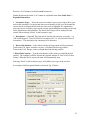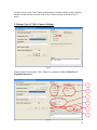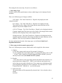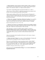
1
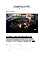
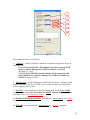
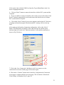
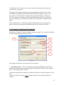
SwanSoft Technologies
iTrainDriver™
Video Train Driver – Digital™
V1.16
User’s Guide Part 1 – Quick Start
For Windows XP
And
‘Hornby Digital’, ‘Digital Plus’ by Lenz and ‘Roco Digital’
DCC Systems
(Document Version 1.16.3 – March 2012)
Copyright© SwanSoft Technologies 2005-2012
1
Contact:
SwanSoft Technologies
PO Box 253
Glen Iris 3146, Australia
E-mail:
Website:
[email protected]
http://www.swansoft.com.au
http://www.videotrainsimulator.com.au
All rights reserved.
The content of this instruction manual is furnished for informational use only; it is subject
to change without notice. The author assumes no responsibility or liability for any errors
or inaccuracies that may appear in this instruction manual.
No part of this publication may be reproduced, stored in a retrieval system, or
transmitted, in any form or by any means, electronic, mechanical, recording, or
otherwise, without the prior written permission of the author.
2
Table of Contents
About this Instruction Manual
4
SwanSoft Technologies iTrainDriver - Video Train Driver - Digital™
User’s Guide
4
Part 1 - Quick Start Instruction
Quick Start – Step 1: Installation and Program Start
1.1 Software Installation
1.2 Systems Setup
1.3 Lenz ‘Digital Plus Interface Modules
1.4 Checking the Interface Configuration and Connection
1.4.1 For Lenz LI-USB Device
1.4.2 For Lenz LI101F Device
1.5 Program Start
1.6 License and Unlock Key
6
6
7
11
12
12
14
16
16
Quick Start – Step 2: Controlling and Simulating a Train
2.1 Preparing a Train for Model Railway Computer Control
2.2 Setting up Interface Configuration and Connection
2.3 Locomotive Selection and Connection
2.4 Image Type & Video Camera Settings
2.5 Screen Resolution Change
2.6 Video Capture System Selection and Connection
2.6.1 Video Capture Adapter Type Selection
2.6.2 Capture Properties
2.6.3 Pin Properties
2.7 Video-captured Model Train Driving Simulator Page
2.7.1 Controlling and Driving a Train
2.8 Thank you
19
19
19
22
24
27
28
28
29
31
33
34
36
3
About this Instruction Manual
SwanSoft Technologies creates and provides a video captured simulation product line of
computer programs and electronic products for use with digitally and conventionally
controlled model railways and cranes.
These products provide a drivers eye view simulation of train and model crane
control via a micro wireless video camera link from the screen and keyboard of your
computer and/or the optional device of a “Raildriver” desktop cab controller for the
model train, or a joystick or game pad controller for the model crane.
¾ Video Train Driver - Digital™ software product is for any model train with a
decoder in DCC format. It is supported by any Digital Command Control system.
¾ Video Train Driver - Conventional™ software product and a USB interface, the
Conventional Train Controller/Device is for any model train without a decoder. It
is supported by any Analogue (12-14V DC) Model Train system.
¾ Video Crane Operator - Digital™ software product is for any model crane with
a decoder in DCC format.
¾ Video Crane Operator - Conventional™ software product and a USB interface,
the Conventional Crane Controller/Device is for any model crane without a
decoder. It is supported by any Analogue (12-14V DC) Model crane system.
SwanSoft Technologies
‘Video Train Driver - Digital™’
User’s Guide
An overview of the concepts of Video Train Driver - Digital™ is provided in this
User’s Guide. By reading this instruction manual one can obtain information about many
features of the product. Additionally you are provided with background information
necessary for model railway computer control with Video Train Driver -Digital™.
Two instruction manuals are provided with this Video Train Driver - Digital™ software
product:
¾ Part 1 provides a Quick Start Instruction for users, who want to start quickly.
¾ Part 2 provides an Expanded Instruction. Knowing the contents of this Guide
will assist you to control the train programs and to maximize your enjoyment
to SwanSoft Technologies’ unique video-capture technology.
The Expanded Instructions are also found on the CD included unit in this
package.
Details of usage are mentioned only if they are necessary to understand the related issues,
or to point to important features of the program.
4
Part 1
Quick Start
5
Quick Start – Step 1:
Installation, Setup and Program Start
‘Video Train Driver – Digital™’ is a video captured model train driving simulation
software product to operate a model train on your layout from a personal computer
running Microsoft Windows XP & Windows 2000.
Quick Start Instructions will enable you to quickly set-up and enjoying the basic
functions of this innovative product.
To gain the maximum benefit from the many options within the program we strongly
recommend that you read the Expanded Instructions in Part 2 of this Users Guide.
The Expanded Instructions are also found on the included CD and can be loaded to your
computer for easy access and ready reference during later use.
1.1 Software Installation
IMPORTANT: Prior to the installation of SwanSoft Technologies – Video Train
Driver - Digital™, please ensure you have downloaded the following:
1. Microsoft Windows XP Updates, including Service Packages
from Microsoft website for smoother and better video-capture and audio performance.
The installation file of SwanSoft Technologies – Video Train Driver - Digital™ is
called SETUP.EXE and can be started from the CD ROM Disc provided with the
package.
After starting SETUP.EXE an instructional window is displayed that guides you through
the steps necessary to install Video Train Driver - Digital™ on your computer.
6
1.2 Systems Setup
For effective operation, SwanSoft Technologies – Video Train Driver - Digital™
requires either Hornby’s Elite Digital Controller, Lenz ‘Digital Plus’ or Roco Digital
DCC systems plus a Lenz ‘Digital Plus’ Computer-DCC Interface Device (LI-USB or
LI101F) connected to the XpressNet of the DCC system and the USB port of the
computer.
After software installation and before you start running Video Train Driver - Digital™
you should connect your Hornby’s Elite Digital Controller, Lenz ‘Digital Plus’ or Roco
Digital DCC system and the
1) Lenz ‘Digital Plus’ Computer-DCC Interface Device (LI-USB or LI101F)
through which you are simulating and controlling your model train (Fig. 1
below, Fig 2 & 3, page 8 & Fig. 4, page 9).
Illustrations for Hornby’s Elite Digital Controller are not included in this
guide, refer to the manual for the Hornby’s Elite Digital Controller provided
by the Hornby.
2) Video-Capture system to the computer using the USB Linkages as shown in the
diagram (Fig.5, page 10).
If unsure, please refer as necessary to the instructions provided by
1) Hornby for Elite Digital Controller, Lenz ‘Digital Plus’ or Roco Digital DCC
systems
2) Video-Capture systems – refer to the manual provided by the manufacturer of
your chosen product
Fig. 1
OR
7
Fig. 2
OR
Fig. 3
OR
8
Fig. 4
9
IMPORTANT:
Do not use a USB Port Hub unit to connect any of the following USB Linkages:
1. USB-XpressNet Interface device (Hornby’s Elite Digital Controller, LI-USB or
LI101F)
2. USB-Video capture device
3. RailDriver USB-Train Driver Control Console device as optional
Connect each separately and plug directly into different USB ports of the computer
otherwise problems will occur.
Fig. 5
10
1.3. Lenz ‘Digital Plus’ Interface Modules
Only the two latest version computer interface devices, LI-USB and LI101F will be
used in this guide. Illustrations for the new LI-LAN/USB are not included in this
guide but it is similar to LI-USB.
LI-USB – USB Computer Interface device
Fig. 6
LI101F - RS-232 High Speed Serial Computer Interface device
Fig. 7
USB - Serial Converter – Adapter (Optional)
Fig. 8
This USB – Serial Converter / Adapter (Fig. 8 above) is used to connect the LI101F
- Computer Interface device with RS232 serial port to interface with the ‘Video
Train Simulator’ software for a better performance via USB Linkage.
Please follow the adapter’s instruction manual and use the CD driver provided with
the adapter to install the connection programs and set the configurations as required.
11
1.4. Checking the Interface Configuration and Connection
Set the Lenz ‘Digital Plus’ or Roco Digital DCC equipments and Lenz ‘Digital
Plus’ LI-USB Computer Interface device or LI101F Computer Interface device and
RS232 High Speed USB-Serial Converter device as per the instruction manuals and
use the CD driver provided with this device to install the connection programs and
set the configurations as required for this device.
For Hornby, refer to the manual for the Hornby’s Elite Digital Controller provided
by the Hornby.
After the cable connections from the Hornby’s Elite Digital Controller, Lenz
‘Digital Plus’ or Roco Digital DCC systems and Lenz ‘Digital Plus’ computer
interface device to the computer are completed, please ensure you select the correct
interface connection settings and configurations for the Hornby’s Elite Digital
Controller or Lenz ‘Digital Plus’ computer interface device.
Set the setting and configuration for the Computer Interface device as follows:
1.4.1. For Hornby’s Elite Digital Controller or Lenz LI-USB Device
a) Check the Hornby’s Elite Digital Controller or Lenz ‘Digital Plus’ LI-USB
Device on Device Manager for COM Port Number on Win XP
On the Windows, place the cursor on “Start” → “Control Panel” →”System”
→”Hardware” → “Device Manager”. Double click on “Ports (COM & LPT)” and it
will show a list of used ports as shown on the next page (Fig.9, page 13).
For example, “USB Serial Port (COM4)” you can see “COM4” as the Port number
which you will use for the ‘Video Train Driver - Digital™’ system. Please
remember this as you will need to enter it in the ‘Video Train Driver - Digital™’
program.
Depending on the USB port used for the Hornby’s Elite Digital Controller or
LI-USB device, the COM Port could register as any number. Make sure you have
the correct COM Port number for the device you are using for the ‘Video Train
Driver - Digital™’ system.
It is important that you make sure the Hornby’s Elite Digital Controller or LI-USB
device and its cable is plugged into the same USB Port every time whenever it is
interface connected to the computer otherwise the device’s configuration popup
screen would come up and ask you to set up another connection for a different USB
Port.
12
Fig.9
b) Set the Lenz LI-USB Computer Interface device to connect
After clicking the Lenz ‘Digital Plus’ LI-USB Server from “Start” → “All
Programs” → “Lenz ‘Digital Plus’” → “LI-USB Server” on the menu bar on
Windows or on the ‘LI-USB Server’ icon on the Windows desktop, the screen will
display as shown on the next page (Fig. 10, page 14).
Please make sure the server is switched “OFF” for this device with the message
“Server is not running” highlighted in red as shown in Fig. 11, page 14. (If unsure
please refer to its instructions provided with the device)
If the Lenz LI-USB Server reads ‘Server is running’ highlighted in green, the
‘Video Train Driver - Digital™’ program will not be able to connect with the
Lenz LI-USB device and it will not work.
It is important that Lenz LI-USB Server is switched off at all time when using the
‘Video Train Driver - Digital™’ program.
13
Click on “Stop server” button to switch off the Lenz LI-USB Server
Fig. 10
Fig. 11
1.4.2. For Lenz LI101F Device
a) Check USB-RS232 (Serial) Adapter on Device Manager for COM Port
Number on Win XP
If a USB – Serial Converter – Adapter is used and connected with an LI101F
Computer Interface device a COM Port Number will be automatically generated for
your use.
To check this COM Port number:
Place the cursor on the Windows to “Start” → “All Programs” → “Control Panel”
→ ”System” → ”Hardware” → “Device Manager”. Double click on “Ports (COM
& LPT)” and it will show a list of used ports as shown on the next page (Fig.12,
page 15).
For example in “Prolific USB to Serial Bridge (COM5)” you can see “COM5” as
the Port number which you will need to use with the ‘Video Train Driver –
Digital™’ system. Please remember this number as you will need to enter it in the
Video Train Driver - Digital program.
14
(Please note that depending on the Brand of USB-RS232 (Serial) adapter you are
using, you may be generating new COM Port numbers for different brands so
remember to match the COM Port number to the correct adapter.)
Fig. 12
b) Set the Lenz LI101F Computer Interface device to connect
After clicking the Lenz LI101F Tool from “Start” → “All Programs” → “Lenz
‘Digital Plus’” → “LI101F Tool” on the menu bar of Windows or on the LI101F
Tool icon on the Windows desktop, the screen will display as shown in Fig. 13
below.
Please set the configurations as required. (If unsure please refer to the instructions
provided with the device) Please remember the baud rate (57600 recommended) as
you will also need to be entered in the ‘Video Train Driver – Digital™’ program.
Fig. 13
15
1.5 Program Start
After the correct installation of Video Train Driver - Digital™, there should be an icon
or entry in the Start menu of your Windows system or on the Video Train Driver Digital™ icon on the Windows desktop as shown →
Click the cursor on it to start the software.
1.6 License and Unlock Key
After the start of the program, it first inquires a license key (Unlock Key).
Fig. 14
Click the cursor on the “Show” command button to display your unique system key and
the instructions as shown below. You can click the cursor on the “Show again” command
button to display other unique system key.
Fig. 15
16
You will need an unlock key to activate the Video Train Driver - Digital system. The
unlock key is provided from SwanSoft Technologies via the “Unlock” page on the
iTrainDriver Website – www.itrainriver.com (International) or www.itraindriver.com.au
(Australia) as shown below
Fig. 16
You then insert your personal and CD disc details as displayed above.
The Serial key is provided on the back of the CD disc case and the System code is
provided from the unique system key on the first screen page of the Video Train Driver Digital system as shown on the previous page (Fig. 15, page 16).
Click the cursor on the “Get Unlock Key” button to proceed. The unlock key will be
provided by email within 24 hours.
After receiving the Unlock key and instructions in your email from SwanSoft
Technologies:
1. Re-enter your “unique system” key by pushing “Show” or “Show Again” button.
2. Insert the “Unlock key” code in the five box display
3. Click the cursor on the “Verify” button to activate the Video Train Driver Digital system as shown in Fig.17, page 18.
17
Fig. 17
This would usually be done only once but you will need to unlock again if you are reinstalling the Video Train Driver - Digital software product. Please retain and store the
keys for future use.
If you are changing the system to another computer you will not able to activate the
Video Train Driver - Digital system with the same unlock keys. You need to contact
SwanSoft Technologies using the “Unlock” page on the iTrainDriver’s website to provide
you another set of different unlock keys.
After you have been licensed with this Video Train Driver - Digital™ software product,
the ‘Introduction’ screen will appear automatically every time you start this program as
shown in Fig. 18, page 19:
18
Quick Start – Step 2:
Controlling and Driving a Train
The ‘Introduction’ screen page as shown in Fig. 18 below is displayed as the first page
when the program starts.
Fig. 18
2.1 Preparing a Train for Model Railway Computer Control
Place a locomotive with a wireless mini video camera fitted in it on the tracks of
your layout and run it with the Digital control system. This is to verify that the
Digital control system and the locomotive are correctly running and also remember
the locomotive code for this ‘Video Train Driver - Digital™’ program.
2.2 Setting up the Interface Configuration and Connection
Press the “Continue” button on the ‘Introduction’ screen page to continue to the
next screen ‘Interface Configuration and Connection’. On this page you will need to
configure the interface between the DCC system and your Computer as shown in
Fig. 19, page 20:
19
1
2
3
4
5
6
Fig. 19
The settings need to be set as follows:
1. COM Port – Set the COM Port to match the Computer set up for the device as
established via:
1.4.1 a) Check the Hornby’s Elite Digital Controller or Lenz LI-USB
Device on Device Manager for COM Port Number on Win XP
(Ref page 12 - 14) or
1.4.2 a) Check USB-RS232 (Serial) Adapter for the connection with
Lenz LI101F Device on Device Manager for COM Port Number on
Win XP (Ref page 14 & 15).
2. Interface Type – Set this, depending on which interface device – Hornby’s Elite
Digital Controller, LI101F or LI-USB - you are using with the Lenz ‘Digital Plus’
or ‘Roco Digital’ DCC system.
3. Baud Rate – Set the baud rate to the same setting as that on the Lenz LI101F
Tool instructed in from 1.4.2 b) Set the Lenz LI101F Interface device to connect
(Ref: page 14 & 15) (57600 recommended).
For Hornby’s Elite Digital Controller, the baud rate is automatically set at 19200
as standard.
For LI-USB device, the baud rate is automatically set at 57600 as standard.
20
Click on the 3 above fields (COM Port, Interface Type & Baud Rate) in the List
boxes to highlight and select.
4. Click on “Select” button to connect the interface with the DCC system and the
Computer.
5. If you are unable to connect an interface device then you can click on the “Find
Device” button to automatically search and connect the interface device with the
DCC system and the Computer.
6. Click on the “Reset” button if you want to unprotect and refresh all 3 list boxes
of settings and start them again. Reset them and all 3 settings will set to the top
field.
After setting up the Interface Connection configuration, click on the “Select”
button. The information will display in the white message box and the green
indicator light will switch “On” when the interface is successfully connected (as
shown in Fig. 20 below).
6
7
8
Fig. 20
7. Click in the ‘Save Connection’ checkbox to tick if you want to save the
connection for next time and the page will not show again.
8. Click on the “Continue” button on the ‘Interface Configuration & Connection’
screen page to continue and the next screen page ‘The Locomotive Selection &
Video Setting’ will display (Fig.21, page 22).
21
9. Click on the “Exit” button if you want to close this screen and return back to the
‘Introduction’ screen page
This page will be displayed again if you have unplugged the interface device from
the USB Port or plugged it in a different USB Port on the computer or the power is
not turned to “ON” on the DCC system before starting the Simulator. The tick in
the ‘Save Connection’ checkbox will be automatically unsaved. If you would like to
save the connection, you will need to click the “Save Connection” checkbox to tick
again.
If the connection fails, a red indicator light is displayed and the error message box
appears with an error description and instructions of what you need to do next.
2.3 Locomotive Selection and Connection
Click on the “Continue” button to continue and the next page ‘The Locomotive Selection
& Video Setting’ displayed as shown below.
1b
1a
2
3
4
5
Fig. 21
The settings for the above screen need to be set as follows:
1. Locomotive Code: – N.B: You will have previously established a program code
number for each locomotive using the Hornby’s Elite Digital Controller, Lenz ‘Digital
Plus’ or ‘Roco Digital’ DCC systems:
a) Enter the matching code number for the chosen locomotive into the Locomotive Code
box.
b) Then click the cursor on the “Next” button to unprotect the remained fields and
continue.
22
Press the “List” button to list all the saved locomotives.
Further Instruction about the “List” button are explained in the User Guide Part 2 Expanded Instruction.
2. Locomotive Type: – Select the correct locomotive type you are using to drive your
train on this simulator. Use the up and down arrow button to scroll up or down until the
correct details are displayed then click the cursor on it to highlight. It is important to
select the correct locomotive type so that accurate speed and distance reading can be read
on the Speedometer and Odometer. The Diesel Fuel Gauge will be displayed on the
console when selecting ‘Diesel’ as the locomotive type.
3. Description: – (Optional) The train can be described or named as you prefer – e.g.
“The Orient Express - Class 103 Electric Locomotive No2” or “My Favourite Electric
Locomotive”. The description can contain up to 50 characters.
4. Driver Side Position: – Select which side the driving console will be positioned.
Trains in the UK, Japan, Australia, etc have a Left-hand side driving position.
Trains in the USA, Europe, etc have a Right-hand side driving position.
5. Diesel Fuel Capacity: - Type the total distance of the journey to establish the fuel
capacity. The computer will now allocate the required amount of “Fuel Load” for that
journey. When the fuel is run out, the train will automatically stop.
Selecting ‘Diesel’ as the locomotive type, will enable you to type in the text box.
An example of all the required details is shown in Fig. 22 below.
Fig. 22
23
Click the cursor on the “Next” button at the bottom to continue and the screen expands to
another column with the inclusion of the Video Camera settings as shown in Fig. 23
below.
2.4 Image Type & Video Camera Settings
Fig. 23
Further Instructions about the “Help” Button are explained in User’s Guide Part 2 –
Expanded Instruction.
1
2
3
4
6
5
Fig. 24
24
The settings for the screen (Fig. 24) can be set as follows:
1. Video Image Type:
Click the cursor on the option button to choose which image is to be displayed for the
simulator.
There are 4 different types of images available:
a) PC Image: - The Video Train Driver – Digital is only displayed on the
computer monitor.
b) TV Image: - The Video Train Driver - Digital is to be displayed on the
Television screen for a bigger video image but the control functions will be
displayed only on the computer screen.
c) PC & TV Image: - The Video Train Driver - Digital is to be displayed on both
Computer monitor and Television screen for a bigger video image but the control
functions will be displayed only on the computer screen.
d) Image not used: - The Video Train Driver - Digital is to be displayed on the
computer monitor without the video image and only the control functions will be
displayed. This is for any locomotives without the camera.
For more information about the video image type, see the User’s Guide Part 2 –
Expanded Instruction.
2. Video camera in the locomotive powered by? :
There are 3 different power sources which can be used to supply the video camera:
a) Battery:
1) The video camera can be powered by a normal 9v battery or
2) A 9V regulated DC power adapter with a 9V rechargeable battery such as ‘SST
- EC60-1 Video Camera Power and Rechargeable Battery Module’ powered
directly from the track (Not suitable for DCC systems)
b) Decoder:
3) The video camera can be powered by the decoder fitted in the locomotive via
an anti-interference adapter (SST – ED62-1) used with an extra function wire
such as the green or purple coloured wire. If two cameras are used then use both
green and purple coloured wires will be employed. You will need 2 DCC Video
Camera Filter (SST - ED61/80-1) – one for each camera.
c) Camera not used:
This option button will be automatically selected when 1 d) is selected as above
(Image
not used).
25
3. Function Number/s for the camera/s in the locomotive, railcar or train set:
Your locomotive may be fitted with one or two camera/s. Select either the option
button 1 or 2 camera/s to control 1 or 2 camera/s in the locomotive.
Type in their corresponding program code Function number/s in 1st /and 2nd
camera/s boxes. (If not sure how to establish the programmed code number for the
decoder, refer to the instruction provided with the decoder)
(Railcars such as the Roco 43022 or 63013 Class 628 railcars will easily take 2
cameras which can be fitted to both ends). Instruction on how to install the cameras
in the Roco 43022 or 63013 Class Railcars are provided in the other instruction
booklet in this package.
4. Click on the ‘Automatic Train/Camera Direction’ checkbox if you would like
the cameras to automatically switch the power supply from the front to the back
camera or from the back to the front camera when the locomotive is changing
direction from forward to reverse or vise versa.
5. Click the “Test” button to test whether the camera has successfully switched
on. If the camera has successfully switched on, the LED on the DCC Video Camera
Filter (SST – ED61/80-1) in the locomotive will be activated.
If this failed then try again with a different function number as stated on 3.
Function Number/s for the camera/s in the locomotive, railcar or train set (Fig.
24, page 24). You will first need to click the “Off” button to switch off the function
of that number before you try to switch on a different function number for the
camera.
Otherwise check and rectify the problem which may be in the camera, wirings or
decoder programming.
6. Click on the “Reset” button if you want to refresh and initialize all settings and
start them again. Resetting them returns all settings to blank fields.
When you are satisfied that the camera is operating correctly, click the “Start”
button to continue to the program. Work through the next few small pop-up pages: the ‘Screen Resolution Change’, the ‘Video-Captured’ system configuration and
setting pages before the main screen ‘Video-captured Model Train Driving
Simulator’ will open as shown on Fig. 25, page 27.
Instructions for the “Screen Resolution Change” are in the User’s Guide Part 2 –
Expanded Instruction.
26
Fig. 25
2.5 Screen Resolution Change
Fig. 26
Click the cursor on the “Yes” button if you would like the Video Train Driver program to
expand and fully cover the whole screen in 800 x 600 pixel size as shown below.
Please note that the screen in 800 x 600 pixel size will not be in high definition quality
resolution.
27
Fig. 27
Click the cursor on the “No” button if you do not wish to change the screen resolution to
800 x 600 pixel size. This will keep the screen resolution in the Windows XP default
setting. The Video Train Program screen will be reduced to a smaller size (for example
1280 x 1024 with your selected coloured background screen behind it. This will provide
much higher definition and clearer resolution.
Further information about screen size and resolution is in the User’s Guide Part 2 –
Expanded Instruction.
2.6 Video Capture System Configuration, Settings and Connection
2.6.1 Video Capture Adapter Type Selection
When starting the simulator program, the Video Train Driver main simulator screen, the
Video Capture Adapter Type Selection, Filter/Capture Properties and Pin Properties
screen pages will be automatically displayed step by step straight after the Screen
Resolution Change screen page is completed (Fig.26, page 27). The ‘Video Capture
Adapter Type Selection’ is the first screen page displayed on the main simulator screen as
shown in Fig. 28, page 29.
The Driver Installation disc included with the USB Video Capture interface adapter must
be loaded onto your computer before the program will operate correctly and displayed as
an optional choice under “Video Capture Adapter Type Selection” alternatives as shown
in Fig. 28, page 29.
If you are unsure about the adapter’s set up, configuration and connection to the
computer, please refer to the instruction manual provided with the USB video-capture
adapter to see how this is done.
28
Fig. 28
Please note: Depending on the type of USB-Video Capture adapter you use, the
Filter/Capture Properties and Pin Properties screen pages may be different. If necessary
refer to the specific user manual for that product.
Click the cursor on the field in the List box to highlight and select the USB-Video
Capture adapter you are using for this simulator program and then click the cursor on the
“Insert” command button to interface connect as shown in Fig. 28 above.
It is important that you make sure that the USB-video capture interface adapter and its
cable is plugged in the same USB Port everytime when it is interface connected to the
computer otherwise the adapter’s configuration screen page will come up asking you to
set up another connection for a different USB Port.
2.6.2 Capture Properties
2.6.2.1 Video Proc Amp – Picture Settings
You can adjust the picture brightness, contrast, hue and saturation by placing the cursor
on the scroll bars/buttons and draging with the mouse or using the Left and Right arrow
buttons on the key board to scroll either left or right to suit you as shown in
Fig. 29, page 30.
29
Fig. 29
2.6.2.2 Image – Image Settings
Depending on the availability of the Video Image format used in your country, select the
correct Video Image format by clicking the cursor on the “Image” Tab button to open the
“Image” folder as shown in Fig.30, page 31. (Also check the Video Image format of the
wireless camera/receiver you have purchased to indentify if it is “NTSC” or “PAL”)
Click the cursor on the option buttons to select the correct format and video source as
shown in Fig.30, page 31. “NTSC” format is used in USA, “PAL” format is used in
Europe, Australia, etc. Depending on the video source output you are using, select either
“Composite Video” for RCA cable or “S-Video” for S-Video cable.
If you are unsure about the adapter’s video source, please refer to the instruction manual
provided with the USB video-capture adapter.
No other settings in this panel need to be adjusted.
When the adjustment is completed to your satisfaction then click the cursor on the “OK”
command button to set and close this screen page.
30
Fig. 30
2.6.3 Pin Properties
You can adjust the Picture Performance (Colour/Space Compression), Speed (Frame
Rate) and Size (Output Size) by placing the cursor on the list boxes to select the field to
comfortably suit you as shown in Fig.31 below & Fig. 32, page 32.
Fig. 31
31
Fig. 32
In making a good balance between quality and best performance of the image, the Frame
Rate: 30 (Maximum), the Colour Space/Compression: “YUY2” and the Output Size:
“320x240” were found to be the best combination for this simulator program.
When the adjustment is completed to your satisfaction, click the cursor on the “OK”
command button to set and close the screen page as shown in Fig 33 below.
Fig. 33
32
2.7 Video-captured Model Train Driving Screen
After clicking the “Start” button on the Locomotive Selection and Video Setting screen
(Fig 25, page 27) and successfully continue through to a few small screen pages (the
Screen Resolution Change, the Video-Captured system configuration and setting), the
main screen - ‘Video-captured Model Train Driving Screen’ comes up with a Video
captured image displayed on the windscreen of the locomotive driver’s compartment as
shown in Fig. 34 below.
13.
17.
18.
14.
16.
15.
19.
5.
2.
3.
9.
1.
4.
6.
7.
12.
11.
10.
8.
Fig. 34
1. Cabin Light Control
2. Emergency Indicator
3. Odometer
4. Emergency Stop Button
5. Speedometer
6. Gear Control
7. Throttle
8. Brake
9. Throttle Control Button
10. Power Control Knob
11. Controls for auxiliary Functions
12. Headlight Control
13. Digital Clock Display
14. Locomotive Code
15. Direction Indicator
16. Throttle Control
17. Headlight Indicator
18. Brake Indicator
19. Fuel Gauge
(For Diesel Locomotives)
33
2.7.1 Controlling and Driving a Train
Fig. 35
1. Power Control Knob
2. Gear Shift Control
3. Parking Brake/Brake Shift Control
4. Throttle Control Slider
2.7.1.1 Starting to control and drive the train
There are 4 main control components as shown in Fig. 35 above, that you will use most
of the time to control and drive the train.
2.7.1.2 To start and drive the train
1. Firstly, click the cursor on the Power Control Knob (1.) to turn ‘ON’ the power and the
green light will activate above the knob.
2. Secondly, click the cursor on the Gear Shift Control (2.) and it will shift the gear to the
‘Forward’ position.
3. Thirdly, click the cursor on the Parking Brake/Brake Control Shift (3.) and it will
release the parking brake.
34
4. Lastly, activate the Throttle Control Slider (4.) using any of the following options:
•
•
•
Left click, hold down and drag down the Throttle Control Slider with the
mouse
Use the scrolling wheel on the mouse
Use the ‘Down’ arrow on the keyboard
In any choice, the train will move and accelerate as the slider moves further down.
To decelerate the train, use any of the above options to move the slider in the opposite
direction and the train will slow down and stop as the slider moves further up to the end.
The speedometer needle moves with the movement of the throttle slider and indicates the
scale speed of your running train and the odometer indicates the scale distance you have
travelled.
To reverse the locomotive, you must first stop the train, then click the cursor on the
Gear Shift Control (2.) and it will shift the gear from the ‘Forward’ position to ‘Reverse’
position.
To turn ‘OFF’ the power, you must stop the train and click the cursor on the Brake Shift
(3.) to pull up the parking brake, then click the cursor on the Power Control Knob (1.)
and it will turn from ‘ON’ position to ‘OFF’ position.
There are many more things that the Video-capture model train driving simulator can do
for realistic control of your trains. You can operate auxiliary functions(Light, horn,
whistle, coupler, etc.) simulate the consumption of resources, adjust the moment to your
personal needs and scale the speed and distance measurements to the physical
characteristics of your train. This is discussed in detail elsewhere in the User’s Guide Part
2 - Expanded instruction manual.
2.7.1.3 Other Control Functions on the console
1. Cabin Interior Light Control – Click the cursor on this button to switch ‘On’ or
‘Off’ the light. See Section ’10.2.4. Day and 10.2.5 Night’ on page 56-58 of
User’s Guide Part 2 – Expanded Instruction.
2. Emergency Stop Button – Click the cursor on this button to immediately stop the
train to avoid accidental situations. Click on it again to release the emergency stop
and bring the control back in a normal operation. The emergency indicator will
also display the status of the operation.
3. Throttle Control Button – Click the cursor on this button to switch to either
‘Automatic’ or ‘Manual’ throttle operation. In the automatic operation, click the
cursor on the throttle slider and it will automatically slide down to accelerate in
incremental steps proportionally with time to the maximum. Click on it again to
automatically slide up to decelerate and stop. Throttle Control Type Indicator will
also display the type of throttle operation.
35
4. Headlight Control - Click the cursor on this button to switch ‘On’ or ‘Off’ the
Head and Rear lights
5. Controls for auxiliary Functions – See in the User’s Guide Part 2 – Expanded
Instruction.
6. Diesel Fuel Gauge – See Section ‘10.4.2 Diesel Fuel Setting’ on page 77-78 of
User’s Guide Part 2 – Expanded Instruction.
7. Locomotive No textbox – After turning the Power Knob to “Off” position, click
the cursor over this Locomotive No textbox and it will return you to the
Locomotive Selection and Connection screen page to select a different train or
locomotive to drive. See section ‘7.3. Locomotive Selection and Connection’ on
page 25-26 of User’s Guide Part 2 – Expanded Instruction.
8. Digital Clock – Double click the cursor on the Clock display to choose either the
Real Time or Fast Clock.
2.8 Thank You!
SwanSoft Technologies wish to thank you for purchasing our innovative product, the
“Video Train Simulator”.
It has been developed for your increased enjoyment and the enhancement of model trains
because we too share a passion for this world-wide, traditional hobby.
We hope you have as much pleasure and excitement using them as we had in developing
them for you.
Happy Train Driving!
36