1
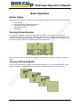
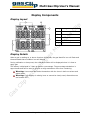
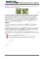
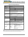
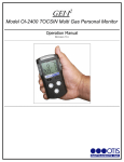
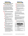
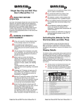
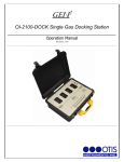
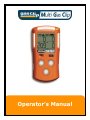
Operator’s Manual Multi Gas Clip User’s Manual Contents Warnings Statements/Avertisseement ..........................................................................................3 READ FIRST BEFORE OPERATION .............................................................................. 3 Basic Operation.......................................................................................................................................4 Button Usage .......................................................................................................... 4 Turning On the Detector........................................................................................... 4 Turning Off the Detector .......................................................................................... 4 Display Components .............................................................................................................................5 Display Layout ........................................................................................................ 5 Display Details ........................................................................................................ 5 Alarms ........................................................................................................................................................6 Default Alarms ........................................................................................................ 6 Alarm Behavior ....................................................................................................... 6 Detector Maintenance: .........................................................................................................................7 Bump Testing ......................................................................................................... 7 Manual Bump Test Instructions .............................................................................. 7 Calibration ............................................................................................................. 7 Manual Calibration Instructions .............................................................................. 7 Battery .................................................................................................................. 8 Instrument Options/Menus ................................................................................................................9 Main Menu: ............................................................................................................ 9 Status Menu: .......................................................................................................... 9 Options Menu: ...................................................................................................... 10 Adjustable Options: ............................................................................................... 10 Instrument Records (Logs):............................................................................................................. 12 Event Log ............................................................................................................. 12 Bump Log ............................................................................................................ 12 Calibration Log ...................................................................................................... 12 Data Logs............................................................................................................. 12 Failures/FAQ’s...................................................................................................................................... 13 Instrument Specifications ................................................................................................................ 14 Contact Information ........................................................................................................................... 14 Limited Warranty................................................................................................................................ 16 V1.8 Portable gas detectors you can count on. 2 of 16 Multi Gas Clip User’s Manual Warnings Statements/Avertisseement Do not substitute components as this may interfere with the intrinsic safety of the device. Ne remplacez pas les composants car cela pourrait interférer avec la sécurité intrinsèque de l'appareil. DO NOT substitute any other battery type than specified and supplied by Gas Clip Technologies. Only use Gas Clip Technologies parts in the detector. Non approved parts will void the warranty and are considered unsafe. Before daily use check that all sensor and audio ports are clear of any obstructions i.e. debris or blockage The detector contains a lithium battery that must be disposed of by a qualified recycler. Check local regulations for proper disposal DO NOT charge the instrument in a hazardous location. DO NOT use IR communications when an explosive atmosphere may be present. If you suspect any malfunction or have any technical problems, contact GCT at 877-525-0808 Warning: The battery may present a fire or chemical burn hazard if mistreated. Do not disassemble, heat above 100°C (212°F), or incinerate. Contact Gas Clip Technologies for replacement instructions. Use of another battery may present a risk of fire or explosion. DO NOT charge the instrument in temperatures above or below the specified range of 0°C to 40°C Keep new and used batteries away from children DO NOT expose the detector to known combustible sensor poisons such as but not limited to alcohol and citrus based cleaners, silicones, lead compounds (eg: tetraethyl lead), sulfur compounds, phosphorus, halogenated hydrocarbons, and aerosols If suspected combustible sensor poisoning has occurred, recheck the instrument (both calibrate and bump test). The detector should be bump tested before use with a known concentration of methane to confirm its ability to respond to gas. Calibrate the detector if the readings are not within the specified limits. Le détecteur doit être testé avant utilisation bosse avec une concentration connue de méthane pour confirmer sa capacité à répondre à gaz. Calibrer le détecteur si les relevés ne sont pas dans les limites spécifiées. Any rapid up-scale reading followed by a declining or erratic reading may indicate a gas concentration beyond upper scale limit which may be hazardous. Toute rapide haut de gamme lecture suivie d'une lecture erratique baisse ou peut indiquer une concentration de gaz supérieure à la limite supérieure de l'échelle qui peut être dangereux. Strong Electromagnetic Interference (EMI) may cause incorrect operaions. Only the combustible gas detection portion of this instrument has been assessed for performance by CSA International. READ FIRST BEFORE OPERATION Gas Clip Technologies (GCT) Multi Gas Clip (MGC) detectors are personal safety devices designed to detect the presence of specific toxic gases Carbon Monoxide (CO), Hydrogen Sulfide (H2S), Oxygen (O2), and Combustible gases/Lower Explosive Limit (LEL). Ensure you have been properly trained on the use of the equipment and appropriate actions in the event of an alarm condition. V1.8 Portable gas detectors you can count on. 3 of 16 Multi Gas Clip User’s Manual Basic Operation Button Usage Operation of the detector is driven by a single button located on the front of the instrument: Turn On/Off Menu Navigation (Status and Options) Latched Alarm acknowledgement Backlight activation Calibration Turning On the Detector To activate the detector, press and hold down the button. If the battery is too low for activation the detector will display “LOW BAT” and then turn off again. Once activated, the unit will begin to display gas readings immediately. Each sensor will show a chasing “O” for the sensor reading while it is stabilizing and being self-tested: “Chasing O” Fully operational Once all sensors have completed the warm up sequence the detector is ready to detect all gases. Turning Off the Detector Press and hold the button to start the shutdown sequence. The LCD will display OFF along with a countdown. Release the button after the countdown and the unit will turn off. V1.8 Portable gas detectors you can count on. 4 of 16 Multi Gas Clip User’s Manual Display Components Display Layout 1 2 3 4 5 Entry Description 1 Alarm Condition 2 Calibration Bottle 3 Battery Level 4 Gas Readings 5 Gas Identifiers Display Details When a gas is reading at, or above its alarm thresholds, the gas identifier icon will flash and the associated alarm condition icon will display. During calibration or bump test, the calibration bottle will be displayed when it is time to apply gas. The battery is displayed in 3 bars as well as a percentage. The percentage calculation is approximate and can be used to provide a rough estimation of the time remaining. Warning: Users must familiarize themselves with the icons in both non-alarm and alarm states. Warning: If the display is missing icons or cannot be clearly read, discontinue use and contact GCT. V1.8 Portable gas detectors you can count on. 5 of 16 Multi Gas Clip User’s Manual Alarms Default Alarms Each detector comes preprogrammed with the factory default Low, High, Time Weighted Average (TWA) and Short Term Exposure Limit (STEL) alarms: Sensor H2S CO O2 LEL Low 10 ppm 35 ppm 19.5% 10% High 15 ppm 200 ppm 23.5% 20% TWA 10 ppm 35 ppm STEL 15 ppm 35 ppm Alarm Behavior The following table describes the detector’s behavior under various alarm conditions: Alarm Condition Low High TWA STEL Multi Sensor Error Low Battery V1.8 Audible Alarm Vibration Alarm Visual Alarm Slow sweep Slow vibration Slow LED Flash Fast sweep Fast vibration Fast LED Flash Slow sweep Slow vibration Slow LED Flash Fast sweep Fast vibration Fast LED Flash Slow/Fast sweep Slow/Fast vibration Slow/Fast Flash Fast sweep Fast vibration Fast LED Flash 20 minutes: single beep/flash. Battery icon on 10 minutes: single beep/flash. Battery icon flashing 5 minutes: continuous beep/flash every 5 seconds expired: 5 long beeps/flashes and then OFF is displayed Portable gas detectors you can count on. 6 of 16 Multi Gas Clip User’s Manual Detector Maintenance: Bump Testing The detector can be configured to keep track of regular bump testing intervals. When the detector has exceeded the bump interval, it will display “BUMP DUE” until it has been successfully bump tested. To bump test the unit, either insert the detector into the Clip Dock test station, or manually apply gas from the bump test screen described below. Manual Bump Test Instructions To activate the manual bump test press the button twice rapidly to enter the user menu. When the screen displays “Show Status” press the button once more. The detector will flash between “BUMP DUE” and “APPLY GAS”. Apply gas to the unit at a flow rate of 0.25 to 0.5LPM using the calibration cap provided. Once all sensors have gone into alarm, the unit will return to normal operation (in alarm) and the bump due date will be reset. If a bump test interval has not been programmed into the unit, users may simply apply gas to the instrument during normal operation. However this will not be recognized as a bump test by the detector and therefore it will be recorded into the event log as an event. Calibration To detector can be configured to keep track of regular calibration intervals. When the detector has exceeded the calibration interval, it will display “CAL DUE” until it has been successfully calibrated. To calibrate the detector, either insert the detector into the Clip Dock test station, or manually calibrate the detector as described below. Manual Calibration Instructions To enter calibration mode, manually press and hold the button down as in the turn off sequence. Continue holding the button down until the CAL screen appears and finishes the countdown. V1.8 Portable gas detectors you can count on. 7 of 16 Multi Gas Clip User’s Manual The detector will first automatically zero the sensors at the current baseline reading. Then the detector will prompt to “APPLY GAS”: Once the screen displays “APPLY GAS”, apply gas to the detector at a flow rate of 0.25 to 0.5LPM using the calibration cap provided. As the detector detects gas, the sensor readings will be displayed as the detector adjusts the calibration parameters. Once calibration is complete the detector will display the next calibration date before returning to normal (alarming) operation. If a sensor fails to calibrate, the detector will display an error for the failed sensor. Check your gas connections and concentration before attempting a second calibration. If a sensor fails to calibrate after a second attempt, contact GCT for either warranty replacement or replacement sensor(s). Battery The battery is displayed as both a percentage and a 3-bar battery icon. The percentage calculation is approximate and can be used to provide a rough estimation of the time remaining. When the detector determines that only 20 minutes of run time remains, it will beep, flash, and display “LOW BAT” on the screen. This will repeat with 10 minutes remaining, and then continuously for the last 5 minutes of run time. When the battery has expired, the detector will give 5 long beeps and flashes, display “OFF” and then shut down. To charge the detector, connect it to the provided charging adapter and plug it into an AC outlet. The detector will cycle the battery icons in a charging fashion until the battery is fully charged. DO NOT charge the instrument in a combustible atmosphere. DO NOT charge the instrument in temperatures above or below the specified range of 0°C to 40°C DO NOT substitute any other battery type than specified and supplied by Gas Clip Technologies. V1.8 Portable gas detectors you can count on. 8 of 16 Multi Gas Clip User’s Manual Instrument Options/Menus To access the user menus press the button two separate times in quick succession (“double tap”). The detector will display: 1. 2. 3. 4. Current date/time User-programmed text message Status menu prompt Options menu prompt If the status menu is accessed by pressing the button during the prompt, the detector will display: 1. 2. 3. 4. 5. 6. 7. 8. Last calibration date When calibration is due Last bump test date When bump test is due Current Time Weighted Average (TWA) readings Current Short Term Exposure Limit (STEL) readings Peak sensor readings Prompt to clear the TWA, STEL and Peak sensor readings (if the button is pressed) If the Options menu is accessed by pressing the button during the prompt, the detector will display: 1. 2. 3. 4. 5. The The The The The detector’s firmware revision TWA alarm limits STEL alarm limits LOW alarm limits HIGH alarm limits Main Menu: Date/Time: Set every time the instrument is communicated via IR Link or Docking Station. User Message: If the message is empty, the detector will skip ahead. If the startup message does not fit on one screen, it will scroll right-to-left twice. Sub-Menu Prompts: Pressing the button during a sub-menu prompt will cause the detector to show more information. If the button is not pressed, the detector will immediately return to normal operation. Status Menu: Calibration Information: The date of the last calibration along with the number of days remaining until the next calibration is due will be displayed. If calibration is due, the detector must be calibrated (refer to the Calibration section) Bump Test Information: The date of the last bump test along with the number of days remaining until the bump test is due will be displayed. If a bump test is due, the detector must be bump tested (refer to the Bump Testing section) Peak Levels: The detector will display the current TWA and STEL readings, followed by the peak concentrations recorded for each sensor. Each time the unit is turned off these values will be reset. V1.8 Portable gas detectors you can count on. 9 of 16 Multi Gas Clip User’s Manual Clear Peak Levels: Pressing the button during the “CLEAR ALL” prompt will cause the TWA, STEL and peak readings to be cleared. Note: this does not remove the information from the internal memory logs of the detector. Options Menu: Firmware Version: The current firmware revision on the detector will be displayed Alarm Set Points: The current alarm limits for TWA, STEL, LOW and HIGH will be displayed in sequence. Adjustable Options: The detector’s options are configured using the IR Link and the MGC IR Link software. User Message: An optional, user-programmable text message can be used to show company branding, a unit identifier, or any other pertinent information. The detector will display this message every time the button is double-tapped. Alarm Limits: Each sensor contains separate alarm threshold values that tell the detector when to go into alarm. Alarm limits may be disabled by setting them to zero. Caution: Confirm alarm levels with local laws/regulations before operation SAFE Display: “SAFE” will be displayed if there are no gas or instrument alerts. Self-Test Lock: When a sensor self-test fails, the detector shows “ERR” on the display and goes into high alarm. The self-test lock option specifies whether a button press can silence the alarm. Maintenance Notification: If maintenance notification is enabled, the detector will periodically flash the maintenance LED. Otherwise, if the option is disabled, the detector will only show the maintenance text on the display. Dock Lock: Dock Lock prevents calibrations and bump tests without the use of the MGC IR Link or the Clip Dock. Latching Alarms: Latched alarms will hold the detector and its display in its peak alarm condition until the button is pressed. Auto-Zero: The detector can optionally zero the sensors with every power-up. TWA Method: The algorithm used to calculate the TWA can be set to either an average over a moving window (OSHA) or as a cumulative average (ACGIH). TWA Interval: The TWA interval defines the timeframe over which the long-term average is calculated. Default is 8 hours. STEL Interval: The STEL interval defines the timeframe over which the short-term average is calculated. Default is 15 minutes. Sensor Enable/Disable: Individual sensors can be disabled. A disabled sensor is completely removed from the detector’s display for sensor readings, alarm limits and calibrations. Caution: A disabled sensor will not measure gas or detect alarm conditions Bump Interval: The bump interval controls how often the detector notifies the user to bump test the sensors. The interval can be individually adjusted for each sensor from 1 to 360 days. Default is 0 (disabled). V1.8 Portable gas detectors you can count on. 10 of 16 Multi Gas Clip User’s Manual Calibration Interval: The calibration interval controls how often the detector notifies the user to calibrate the sensors. The interval can be individually adjusted for each sensor from 1 to 180 days. Default is 180 days. Calibration Gas: When the detector is calibrated, it scales the sensor readings to match the concentrations of the applied gases. The calibration gas concentrations can be adjusted to match the respective levels contained within the gas bottle. Default is: 25ppm H2S, 100ppm CO, 18% O2 and 50%LEL (2.5%vol CH4) Language: The detector will display all of its text prompts in any of English, German, French, Spanish, Italian or Portuguese. Note: OL, Err and sensor icons remain the same for all languages. V1.8 Portable gas detectors you can count on. 11 of 16 Multi Gas Clip User’s Manual Instrument Records (Logs): During operation the detector records all usage activity. These records can be downloaded from the instrument via the MGC IR Link software and an IR Link or from the Clip Dock. The Event, Bump, and Calibration Logs are always downloaded. The user may also choose to download different amounts of the data log to reduce the transfer time. Partial data logs contain approximately 1 weeks’ worth of data. New data log downloads will only contain the data since the last download. Full log downloads will download the entire data log, typically at least 2 months’ worth of data. Event Log The detector stores the last 25 alarm events. These are organized by first in first out (FIFO) so the 26th event will replace the first event, and so on. The detector records the alarm conditions for each event: Date and time at start of event Duration of the alarm condition Each sensor’s peak alarm status and reading Bump Log The detector stores the last 25 alarm events. These are organized by first in first out (FIFO) so the 26th event will replace the first event, and so on. Bump tests are differentiated from normal events when the alarm condition occurs inside of a Clip Dock test station, or when the instrument is manually bump tested according to the Bump Testing section. The detector records the bump status for each test: Date and time of bump test Whether the test was performed manually or in a Clip Dock Each sensor’s peak alarm status and reading The result of each sensor’s bump test Calibration Log The detector records the last 25 calibration attempts. These are organized by first in first out (FIFO) so the 26th calibration will replace the first calibration and so on. Each calibration attempt will be recorded: Date and time of calibration Each sensor’s gas concentration calibrated to Each sensor’s calibration success status Data Logs The detector records its current operational status every second. The logging interval cannot be adjusted, but the detector compresses the data to reduce the storage and transfer times of redundant records. The typical logging capacity is at least 2 months of data. The following items are recorded into the log: V1.8 Date and time Sensor readings and status conditions All user and sensor options Events (i.e. turn on or off) Portable gas detectors you can count on. 12 of 16 Multi Gas Clip User’s Manual Failures/FAQ’s Err: If a sensor is displaying “Err” this sensor has failed and is therefore disabled. Contact GCT for either warranty replacement or replacement sensor(s). BUMP DUE: If the detector is displaying “BUMP DUE”, the detector is either due for a bump test because of a scheduled test or has failed its last bump test. Refer to the Bump Testing section for more details. CAL DUE: If the detector is displaying “CAL DUE” the detector is due for a calibration because of a scheduled interval. Refer to the Calibration section for more details. V1.8 Portable gas detectors you can count on. 13 of 16 Multi Gas Clip User’s Manual Instrument Specifications Size 4.7 x 2.4 x 1.2 in. (118.6 x 61.6 x 31.7 mm.) Weight 7.7 oz. (240 g) Temperature -4 to +122˚F (-20 to +50˚C) Humidity 5% to 95% RH (non-condensing) Battery Life IR 60 days continuous Pellistor 25 hours (typical) Charge Time 4-6 hours Alarms Visual, Vibrating, Audible (minimum 95dB) Low, High, STEL, TWA and OL (Over Limit) LEDs 4 red alarm bar LEDs Yellow backlight (activated on button press) Red backlight (activated on alarm condition) Yellow Maintenance Notification LED Display Alphanumeric Liquid Crystal Display (LCD) Logs 25 Bump Tests 25 Events 25 Calibrations Continuous 1-second data logging (> 2 months typical capacity) Tests Full function self-test upon activation sensors, battery and circuitry continuous Ingress Protection IP66/67 Warranty Full 2 years Gases H2S 0 – 100 PPM (0.1 PPM increments) CO 0 – 500 PPM (1 PPM increments) Combustible 0 – 100 %LEL (1% LEL increments) O2 0 – 30 % vol. (0.1% vol. increments) Sensor Type H2S, CO, O2: Single plug-in electrochemical cell Combustible: Plug-in Infrared (IR) or catalytic bead User Options User Message, Language, Low Alarm, High Alarm, STEL Alarm, TWA Alarm, TWA Method, TWA Interval, STEL Interval, SAFE, Maintenance Notification, Self-test Lock, Dock Lock, Sensor enable, Calibration Interval, Bump Interval, Calibration Gas, CSA: ATEX (PENDING): Approvals IECEx: STANDARDS: Class 1, Division 1, Group A, B, C, and D Class 1, Zone 0, AEx ia IIC T4 Ga CE 0359 II 1 G Ex ia IIC T4 Ga EN 60079-0, EN 60079-11, EN 60079-26 EN 50270 Ex ia IIC T4 Ga C22.2 No.’s. 0, 152, 157, 60079-0, 60079-11 UL-913 UL 60079-0, 60079-11 ANSI/ISA S12.13.01 Note: This equipment has been tested and found to comply with the limits for a Class B digital device, pursuant to Part 15 of the FCC Rules. These limits are designed to provide reasonable protection against harmful interference when the equipment is operated in a commercial environment. This equipment generates, uses, and can radiate radio frequency energy and, if not installed and used in accordance with the instruction manual, may cause harmful interference to radio communications. V1.8 Portable gas detectors you can count on. 14 of 16 Multi Gas Clip User’s Manual Contact Information Gas Clip Technologies, Inc. 218 W Avenue F Midlothian, TX 76065 Toll Free: (877) 525-0808 Phone: (972) 775-7577 Fax: (972) 775-2483 E-mail: [email protected] Website: www.gascliptech.com V1.8 Portable gas detectors you can count on. 15 of 16 Multi Gas Clip User’s Manual Limited Warranty Gas Clip Technologies (“GCT”) warrants this product to be free from defects in material and workmanship under normal use and service for a period of two years beginning upon the date of activation for all Multi Gas Clip products. This warranty extends only to the sale of new and unused products to the original buyer. GCT’s warranty obligation is limited, at GCT’s option, to refund of the purchase price, repair, or replacement of a defective product that is returned to a GCT authorized service center within the warranty period. In no event shall GCT’s liability hereunder exceed the purchase price actually paid by the buyer for the product. This Warranty does not include: (1) Fuses, disposable batteries, or routine replacement of parts due to the normal wear and tear of the product arising from use. (2) Any product which in GCT’s opinion, has been misused, altered, neglected or damaged by accident or abnormal conditions of operation, handling, or use. (3) Any damage or defects attributable to repair of the product by any person other than the authorized dealer, or installation of unapproved parts on the product. The obligations set forth in this warranty are conditional on: (1) Proper storage, installation, calibration, use, maintenance, and compliance with the user’s manual instructions and any other applicable recommendations of GCT. (2) The buyer promptly notifying GCT of any defect and, if required, promptly making the product available for correction. No goods shall be returned to GCT until receipt by the buyer of instructions from GCT. (3) The right of GCT to require that the buyer provide proof of sale or packing slip to establish that the product is within the warranty period. The buyer agrees that this warranty is the buyer’s sole and exclusive remedy and is in lieu of all other warranties, express or implied, including but not limited to any implied warranty or merchantability or fitness for a particular purpose. GCT shall not be liable for any special, indirect, incidental, or consequential damages or losses, including loss of data, whether arising from breach of warranty or based on contract, tort, or reliance on any other theory. Some countries or states do not allow limitation of the term of an applied warranty, or exclusion or limitation of incidental or consequential damages, the limitations and exclusions of this warranty may not apply to every buyer. If any provision of this warranty is held invalid or unenforceable by a court of competent jurisdiction, such holding will not affect the validity or enforceability of any other provision. V1.8 Portable gas detectors you can count on. 16 of 16