1
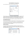
OI-2100-DOCK Single Gas Docking Station ________________________________________ Operation Manual tRevision 2.0w ___________________________________________________________________________________________________ ___________________________________________________________________________________________________ Table of Contents Introduction ........................................................................................................................................ 3 Warnings Statements/Avertisseement.............................................................................................. 4 Basic Operation................................................................................................................................... 5 OI-2100-DOCK Components ...................................................................................................................................... 5 LEDs............................................................................................................................................................................. 5 Operation ............................................................................................................................................ 6 Turning the OI-2100-DOCK On and Off .................................................................................................................... 6 Charging ...................................................................................................................................................................... 6 Calibration Gas Installation ........................................................................................................................................ 6 Button Usage ................................................................................................................................................................ 6 Troubleshooting Failures ............................................................................................................................................ 7 OI-2100-DOCK Configuration .......................................................................................................... 8 OI-2100-DOCK Options ............................................................................................................................................... 8 Detector Options .......................................................................................................................................................... 8 OI-2100-DOCK Records (Logs) ........................................................................................................ 9 OI-2100-DOCK Log Format ........................................................................................................................................ 9 Logged OI-2100 TOCSIN Options .............................................................................................................................. 9 Specifications .................................................................................................................................... 10 Introduction This document is an Operation Manual containing diagrams and step-by-step instruction for proper operation of the Otis Instruments, Inc. Gen II Model OI-2100-DOCK Single Gas Docking Station. This document should be read before initial operation of the product. Should a question arise during the use of the product, this document will serve as a first reference for consultation. If further questions arise, or if the device is not working properly, please contact the sales representative of this product. 3 Warnings Statements/Avertisseement • • • • • • • • • • The OI-2100-DOCK may not support all gases. For a complete list, please contact Otis Instruments. Do not use the OI-2100-DOCK if it appears to be damaged. Inspect it before each use. Ensure the OI-2100-DOCK is used with certified calibration gas. DO NOT use expired calibration gas. Please check the expiration date located on the bottle. DO NOT operate the OI-2100-DOCK in a hazardous environment. Do not expose the OI-2100-DOCK to electrical or mechanical shocks before, during, or after use. Do not allow liquids to condense and/or use high power sprays on the OI-2100-DOCK. Otis Instruments recommends periodic back up of the data stored on the USB Memory. The OI-2100-DOCK contains a lithium battery that must be disposed of by a qualified recycler. Check local regulations for proper disposal. Warning: The battery may present a fire or chemical burn hazard if mistreated. Do not disassemble, heat above 100°C (212°F), or incinerate. Contact Otis Instruments for replacement instructions. Use of another battery may present a risk of fire or explosion. DO NOT charge the docking station in temperatures above or below the specified range of 0°C to 40°C. Read the entire OI-2100-DOCK manual and follow all instructions to ensure proper use and safe installation. 4 Basic Operation OI-2100-DOCK Components LEDs LED Unit LEDs Power LED * The Color Description orange red green green cycling green green blinking orange orange blinking test in progress test failed test passed charging powered on low battery test in progress No USB memory detected* OI-‐2100-‐DOCK will be unable to record test results if USB memory is not installed 5 Operation Turning the OI-2100-DOCK On and Off The OI-2100-DOCK is powered by an internal rechargeable battery that can perform up to 1500 bump tests. Pressing either button will automatically wake up the OI-2100-DOCK and perform the button’s associate actions. The OI-2100-DOCK will automatically turn itself off between tests, unless the charger is connected. Charging Connect the supplied DC power adapter to the Charging Port on the OI-2100-DOCK to charge the internal battery. The Unit LEDs will cycle until the battery is fully charged. A complete charge takes approximately 3 hours and lasts for approximately 1500 bump test cycles. WARNING: DO NOT charge the docking station in temperatures above or below the specified range of 0°C to 40°C DO NOT substitute any other battery type than specified and supplied by Otis Instruments. Calibration Gas Installation The OI-2100-DOCK requires a calibration gas bottle to be installed in order to perform tests on the detectors. To install, remove the Access Hatch Screws (x2) and lift the access panel. Thread the bottle into the CG-10 fitting until tight. Once properly connected, the gas gauge will indicate the bottle pressure. By default, the OI-2100-DOCK assumes that the bottle contains four gases so that any detector model can be tested. The Dock Manager software allows you to specify the gas concentrations. The default concentration is set for a mix of all gas types: H2S: 25 ppm CO: 100 ppm O2: 18% LEL: 50% Button Usage Using the two buttons on the top plate performs operation of the OI-2100-DOCK. Bump Test: Briefly applies gas to ensure that the detectors respond Calibration: Calibrates the detectors’ measurement accuracy against the applied gas Both (hold): Turns off or hibernates the detectors Place up to four activated detectors into the detector bays. The OI-2100-DOCK can test up to four detectors simultaneously. Ensure that the gas bottle matches the gas types required by the inserted detectors. The OI-2100-DOCK can test with different detectors at the same time if using a multigas blend calibration mix. To begin the test, press the Bump Test and/or the Calibration button. A bump test will take approximately 20 seconds; a calibration 90 seconds; hibernation a few seconds. While the test is active, the LEDs will turn ORANGE. When the test has completed, the LEDs will turn GREEN for pass or RED for fail. Wait until the power button shows the overall result (GREEN or RED) before removing the detectors. Every test will perform the following maintenance operations: • • Upgrade each detector’s firmware (if required) Set the detector’s date and time (if supported) 6 Button Usage cont. . . . • • • • • Test each detector’s beeper Configure each detector’s user options (as required) Download each detector’s logs Bump, Calibrate, or hibernate as requested Record the test to the USB memory Troubleshooting Failures 1. 2. 3. 4. 5. Inspect the detector sensor and beeper cavities and clear any obstructions. Clean the small IR communication window located on the top of the detector. Verify the gas bottle is not empty. 58L bottles are “full” at 500 PSI; 116L at 1000 PSI. Try relocating the OI-2100-DOCK away from bright light sources, which may interfere with IR communication between the OI-2100-DOCK and the detectors. If a monitor has failed 3 after three test attempts, please contact the Otis Instruments Service Department. 7 OI-2100-DOCK Configuration The OI-2100-DOCK is configured with the Dock Manager software. The Dock Manager software can communicate with the OI-2100-DOCK through IR or USB as selected by the radio buttons. IR communication is handled through Bay 1 of the OI-2100DOCK and if the IR Link is placed into Bay 1. For IR communication, connect the OI-2100DOCK to a charger and place the IR Link into Bay 1. Direct USB operation with the memory stick connected to the PC offers faster transfers or configuration without an IR Link. OI-2100-DOCK Options The software program will provide a detailed description of each option if the mouse is hovered of it. The Location, Gas Expiration Date and Gas Bottle Lot # are optional parameters that will be recorded into the log file with each test. The checkboxes can enable or disable various features of the OI-2100-DOCK, including: calibrations, bump tests, hibernations, detector configuration and detector firmware upgrades. Detector Options Every detector tested by the OI-2100-DOCK can optionally be programmed with various configuration settings. By default, the OI-2100-DOCK will not reconfigure any detectors. The Dock Manager software allows fine-grained control over which options are programmed into the detectors and what those settings will be. 8 OI-2100-DOCK Records (Logs) The OI-2100-DOCK records the results of each test to its USB memory. In addition, it will download each detector’s event log. OI-2100-DOCK log files are stored in Comma Separated Value (CSV) format, which can easily be parsed by a spreadsheet program for viewing and manipulation. OI-2100-DOCK Log Format The first lines of the log file provide a header for the log data. Each test is stored in multiple lines. Line 1: Overall OI-2100-DOCK test results • • • • • • Date and Time of test Test type (Bump Test, Calibration or Turn Off) OI-2100-DOCK Serial Number Overall pass/fail test result Firmware and Hardware versions Location (optional user string that can be configured with the Dock Manager software) Line 2: Bay test results for the inserted detector • • • • • • • Bay Number (1-4) Detector Model Detector serial number Detector pass/fail result Detector firmware and hardware versions Beeper pass/fail result Detector options (varies by detector type) Line 3: Detector sensor(s) test results • • • • • Sensor Type Sensor pass/fail result Sensor reading Gas bottle details Sensor options (varies by detector type) Logged OI-2100 TOCSIN Options The OI-2100-DOCK logs the following OI-2100 TOCSIN detector options on Line 2: • • • • • Show Sensor Readings (T/F) Bump Flash Disabled (T/F) Hide Clock (T/F) User ID Self-Test Interval The following OI-2100 sensor options are logged on Line 3: • • • High and Low alarms Calibration and Bump Test Intervals Calibration and Bump Due (days) 9 Specifications Size: 18.06 x 12.89 x 6.72 in. (45.9 x 32.7 x 17.1 cm.) Weight: 15 lbs. (6.8 kg.) Temperature: 41 to +104˚F (5 to +40˚C) Battery Life: 1500 Bump Tests Charge Time: 2-3 Hours LEDs: 5 red/green/orange LEDs (1 for each unit, 1 for power) Display: Alphanumeric Liquid Crystal Display (LCD) Log Capacity: Approximately 10 million tests (4 GB, removable USB memory) User Options: Location, Gas expiration date, Gas bottle lot number, gas concentrations, bump gas time, bump sensor pass criteria, calibrations, bump tests, hibernations, detector configuration, firmware upgrades, turn off time NOTE: This equipment has been tested and found to comply with the limits for a Class B digital device, pursuant to Part 15 of the FCC Rules. These limits are designed to provide reasonable protection against harmful interference when the equipment is operated in a commercial environment. This equipment generates, uses, and can radiate radio frequency energy and, if not installed and used in accordance with the instruction manual, may cause harmful interference to radio communications. Warranty: 2 Years 10 Warranty Statement for the Gen II Model OI-2100-DOCK Otis Instruments, Inc. warrants this product to be free from defects in material and workmanship under normal use and service for a period of two years beginning upon the date of purchase. This warranty extends only to the sale of new and unused products to the original buyer. Otis Instruments’ warranty obligation is limited, at Otis Instruments’ option, to refund of the purchase price, repair, or replacement of a defective product that is returned to an Otis Instruments authorized service center within the warranty period. In no event shall Otis Instruments’ liability hereunder exceed the purchase price actually paid by the buyer for the product. This Warranty does not include: (1) Routine replacement of parts due to the normal wear and tear of the product arising from use. (2) Any product that in Otis Instruments’ opinion has been misused, altered, neglected or damaged by accident or abnormal conditions of operation, handling, or use. (3) Any damage or defects attributable to repair of the product by any person other than the authorized dealer, or installation of unapproved parts or gas cylinders on or in the product. The obligations set forth in this warranty are conditional on: (1) Proper storage, installation, use, maintenance, and compliance with the user’s manual instructions and any other applicable recommendations of Otis Instruments. (2) The buyer promptly notifying Otis Instruments of any defect and, if required, promptly making the product available for correction. No goods shall be returned to Otis Instruments until receipt by the buyer of instructions has been received by Otis Instruments. (3) The right of Otis Instruments to require that the buyer provide proof of purchase such as the original invoice, bill of sale or packing slip to establish that the product is within the warranty period. The buyer agrees that this warranty is the buyer’s sole and exclusive remedy and is in lieu of all other warranties, express or implied, including but not limited to any implied warranty or merchantability or fitness for a particular purpose. Otis Instruments shall not be liable for any special, indirect, incidental, or consequential damages or losses, including loss of data, whether arising from breach of warranty or based on contract, tort, or reliance on any other theory. Some countries or states do not allow limitation of the term of an applied warranty, or exclusion or limitation of incidental or consequential damages, the limitations and exclusions of this warranty may not apply to every buyer. If a court of competent jurisdiction holds any provision of this warranty invalid or unenforceable, such holding will not affect the validity or enforceability of any other provision. 11 Otis Instruments, Inc. 2200 E. Villa Maria Dr. Bryan, TX 77802 Service Department: 903.566.1300 Corporate Office: 979.776.7700 [email protected] www.otisinstruments.com 12