1
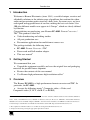
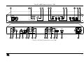
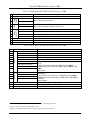
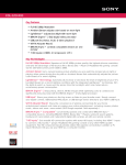
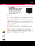
Kramer Electronics, Ltd.
USER MANUAL
Model:
FC-4002
Format Converter / TBC
Contents
Contents
1
2
3
4
5
6
Introduction
Getting Started
Overview
Your FC-4002 Format Converter / TBC
Installing on a Rack
Connecting Your FC-4002 Format Converter / TBC
Connecting a PC
Dipswitch Settings
7
7
7
8
Technical Specifications
Communication Protocol
9
9
6.1
6.2
1
1
1
2
5
6
Figures
Figure 1: FC-4002 Format Converter / TBC
Figure 2: Connecting a PC without using a Null-modem Adapter
Figure 3: Connecting the FC-4002 Format Converter / TBC
3
7
8
Tables
Table 1: Front Panel FC-4002 Format Converter / TBC
Table 2: Rear Panel FC-4002 Format Converter / TBC
Table 3: Output Standard Settings
Table 4: Output Format Settings
Table 5: Dipswitch Settings (DIP 4 and DIP 5)
Table 6: Technical Specifications of the FC-4002 Format Converter / TBC
Table 7: Structure of the Protocol
Table 8: Instruction Set
Table 9: Front-Panel Switch Numbers
4
4
7
7
8
9
10
10
11
i
Introduction
1
Introduction
Welcome to Kramer Electronics (since 1981): a world of unique, creative and
affordable solutions to the infinite range of problems that confront the video,
audio and presentation professional on a daily basis. In recent years, we have
redesigned and upgraded most of our line, making the best even better! Our
500-plus different models now appear in 8 Groups1, which are clearly defined
by function.
Congratulations on purchasing your Kramer FC-4002 Format Converter /
TBC. This product is ideal for:
Video broadcasting and editing studios
All post-production uses
Presentation applications for multi-format sources use
The package includes the following items:
FC-4002 Format Converter / TBC
Power cord and Null-modem adapter
This user manual2
2
Getting Started
We recommend that you:
Unpack the equipment carefully and save the original box and packaging
materials for possible future shipment
Review the contents of this user manual
Use Kramer high performance high resolution cables3
3
Overview
The Kramer FC-4002 is a high performance format converter and TBC. In
particular, the FC-4002:
Accepts the following inputs4: Composite video, s-Video, and
Component video (Y, B-Y, and R-Y; or RGB/S)
1 GROUP 1: Distribution Amplifiers; GROUP 2: Video and Audio Switchers, Matrix Switchers and Controllers; GROUP 3:
Video, Audio, VGA/XGA Processors; GROUP 4: Interfaces and Sync Processors; GROUP 5: Twisted Pair Interfaces;
GROUP 6: Accessories and Rack Adapters; GROUP 7: Scan Converters and Scalers; and GROUP 8: Cables and Connectors
2 Download up-to-date Kramer user manuals from the Internet at this URL: http://www.kramerelectronics.com
3 The complete list of Kramer cables is on our Web site at http://www.kramerelectronics.com
4 An input is selected by pressing the appropriate input selector button
1
Your FC-4002 Format Converter / TBC
Has a looped Genlock input for synchronizing to an external source
Has a highly stable internal generator for independent (non-genlocked)
applications
Outputs the Sync signal, and either: Component video (Y, B-Y, and R-Y;
or RGBS), or when Component video is not selected, both Composite video
and s-Video simultaneously, which is selected on dipswitches
Lets you determine the output video standard (PAL B, PAL M, PAL N,
NTSC 3.58, NTSC 4.43, and SECAM) via the dipswitches
Note, however, that the FC-4002 does not convert between video standards.
In addition, the FC-4002 features:
Front panel buttons for input selection (CV, Y/C, YUV, and RGB/S),
Genlock, freeze and panel lock
Coarse trimmers and fine trimmers for adjusting the sync phase, and the
horizontal-to-subcarrier phase (SCH)
Control via the front panel buttons; and remotely, by RS-232 serial
commands transmitted by a touch screen system, PC, or other serial controller
To achieve the best performance:
Connect only good quality connection cables, thus avoiding interference,
deterioration in signal quality due to poor matching, and elevated noise levels
(often associated with low quality cables)
Avoid interference from neighboring electrical appliances that may
adversely influence signal quality and position your Kramer FC-4002 away
from moisture, excessive sunlight and dust
4
Your FC-4002 Format Converter / TBC
Figure 1, Table 1, and Table 2 define the FC-4002 Format Converter / TBC.
2
KRAMER: SIMPLE CREATIVE TECHNOLOGY
Your FC-4002 Format Converter / TBC
Figure 1: FC-4002 Format Converter / TBC
3
Your FC-4002 Format Converter / TBC
Table 1: Front Panel FC-4002 Format Converter / TBC
3
4
5
6
7
8
9
SYNC
PHASE
Function
Illuminated switch for turning the unit ON or OFF
COARSE Trimmer
SCH
Feature
POWER Switch
FINE Trimmer
COARSE Trimmer
INPUT
SELECTOR
#
1
2
Y/C Button
CV Button
RGB/S Button
YUV Button
1
Adjusts the sync phase level
FINE Trimmer
10 LOCK Button2
11 FREEZE Button
12 GENLOCK Button
1
Adjusts the horizontal-to-subcarrier phase level
Selects the s-Video source for conversion
Selects the composite video source for conversion
Selects the RGB/S source for conversion
Selects the YUV source for conversion
Disengages the front panel buttons
Freezes the output video
Press to enable GENLOCK operation
Table 2: Rear Panel FC-4002 Format Converter / TBC
#
13
14
Feature
LOOP BNC Connector
SYNC BNC Connector
Term Button
16
CV BNC Connector
18
19
20
21
22
23
24
25
OUTPUTS
17
INPUTS
15
Function
Connects to the next Genlocked unit
Connects to the Genlock source
Press to terminate the Genlock source (75 ) or release for looping3
Connects to the composite video source
Y/C 4p Connector
Connects to the s-Video (Y/C) source
G/Y BNC Connector
R/R-Y BNC Connector
SYNC BNC Connector
B/B-Y BNC Connector
Connects to the RGB (connect all 3 connectors: R/R-Y, G/Y, and
B/B-Y),
or YUV (connect all 3 connectors: R/R-Y, G/Y, and B/B-Y),
or RGBS (connect all 4 connectors: R/R-Y, G/Y, and B/B-Y, and
SYNC)
video source
Connects to the RGB (connect all 3 connectors: CV/R/R-Y, G/Y,
and C/B/B-Y),
or YUV (connect all 3 connectors: CV/R/R-Y, G/Y, and C/B/B-Y),
or RGBS (connect all 3 connectors: CV/R/R-Y, G/Y, and C/B/B-Y,
and SYNC)
video acceptor
CV/R/R-Y BNC Connector
G/Y BNC Connector
SYNC BNC Connector
C/B/B-Y BNC Connector
26
SETUP Dipswitches
27
RS-232 Port
Dipswitches setup (see section 6.2)
Connects to the PC or the Remote Controller
28
Power Connector with Fuse
AC connector enabling power supply to the unit
1 Insert a screwdriver into the small hole and carefully rotate it, trimming the level
2 Press for about 2 seconds to lock/unlock the panel
3 Push in to terminate the input. Release when the input extends to another unit
4
KRAMER: SIMPLE CREATIVE TECHNOLOGY
Installing on a Rack
5
Installing on a Rack
This section describes what to do before installing on a rack and how to rack
mount.
Before Installing on a Rack
How to Rack Mount
Before installing on a rack, be sure that the environment is
within the recommended range:
Operating temperature range +5 to +45 Deg. Centigrade
Operating humidity range
5 to 65 % RHL, non-condensing
Storage temperature range
-20 to +70 Deg. Centigrade
Storage humidity range
5 to 95% RHL, non-condensing
To rack-mount the machine:
1
Attach both ear brackets to the
machine. To do so, remove the
screws from each side of the
machine (3 on each side), and
replace those screws through
the ear brackets.
CAUTION!!
When installing on a 19" rack, avoid hazards by taking
care that:
1
It is located within the recommended environmental
conditions, as the operating ambient temperature of a
closed or multi unit rack assembly may exceed the room
ambient temperature.
2
Once rack mounted, enough air will still flow around the
machine.
3
The machine is placed straight in the correct horizontal
position.
4
You do not overload the circuit(s). When connecting the
machine to the supply circuit, overloading the circuits
might have a detrimental effect on overcurrent
protection and supply wiring. Refer to the appropriate
nameplate ratings for information. For example, for fuse
replacement, see the value printed on the product label.
5
The machine is earthed (grounded) in a reliable way and
is connected only to an electricity socket with grounding.
Pay particular attention to supply connections other than
direct connections to the branch circuit (for example, the
use of power strips), and that you use only the power cord
that is supplied with the machine.
2
Place the ears of the machine
against the rack rails, and insert
the proper screws (not provided)
through each of the four holes in
the rack ears.
Note that:
In some models, the front panel
may feature built-in rack ears
Detachable rack ears can be
removed for desktop use
Always mount the machine in the
rack before you attach any cables or
connect the machine to the power
If you are using a Kramer rack
adapter kit (for a machine that is not
19"), see the Rack Adapters user
manual for installation instructions
(you can download it at:
http://www.kramerelectronics.com)
5
Connecting Your FC-4002 Format Converter / TBC
6
Connecting Your FC-4002 Format Converter / TBC
You can use your FC-4002 to convert a composite video, s-Video, or component
video (YUV or RGB/S) signal to either: Component video, or Composite
video and1 s-Video simultaneously. For example, as the illustration in Figure 3
shows, an RGBS output2 that connects to a plasma display.
To connect the FC-4002 Format Converter / TBC, do the following3:
1. Connect the following sources to the FC-4002, the:
Composite video source (for example, a composite video player) to the
CV INPUT BNC connector
s-Video source (for example, an s-Video player) to the Y/C INPUT 4p
connector
2. Connect the component video INPUT BNC connectors, G/Y, B/B-Y,
and R/R-Y to either a YUV or an RGB video source, as follows:
A Betacam video player to R/R-Y, G/Y, and B/B-Y, or
A camera (RGBS) source to R/R-Y, G/Y, and B/B-Y and SYNC
3. Connect the four BNC OUTPUT connectors: CV/R/R-Y, G/Y, and
C/B/B-Y, and SYNC to a video acceptor (for example, a plasma display).
4. Connect the LOOP BNC connector to the next FC-4002 Genlocked unit
(if required) and release the Term button for looping4.
5.
Connect a Genlock source to the SYNC BNC connector.
6.
Connect a PC or other controller, if required (see section 6.1).
7.
Set the dipswitches (see section 6.2).
8. Connect the power cord5 (not illustrated in Figure 3).
You can operate the FC-4002 Format Converter / TBC via the front panel
buttons and/or RS-232 serial commands.
1 When only one output is required, connect that output of the FC-4002, and leave the other outputs unconnected
2 Alternatively, you could connect composite video or s-Video or component video (Y, B-Y, and R-Y, or RGB)
3 Switch OFF the power on each device before connecting it to your FC-4002. After connecting your FC-4002, switch on its
power and then switch on the power on each device
4 Pushed in terminates the input. Release when the input extends to another unit
5 We recommend that you use only the power cord that is supplied with this machine
6
KRAMER: SIMPLE CREATIVE TECHNOLOGY
Connecting Your FC-4002 Format Converter / TBC
6.1 Connecting a PC
To connect a PC to the FC-4002 unit, using the Null-modem adapter
provided with the machine (recommended):
Connect the RS-232 DB9 rear panel port on the FC-4002 unit to the
Null-modem adapter and connect the Null-modem adapter with a 9 wire flat
cable to the RS-232 DB9 port on your PC
Alternatively, to connect a PC to the FC-4002 unit without using a Nullmodem adapter:
Connect the RS-232 DB9 port on your PC to the RS-232 DB9 rear panel
port on the FC-4002 unit, as Figure 2 illustrates
Figure 2: Connecting a PC without using a Null-modem Adapter
6.2 Dipswitch Settings
The FC-4002 dipswitch settings are defined in Table 3, Table 4, and Table 5:
Table 3: Output Standard Settings
FUNCTION
DIP 1
DIP 2
DIP 3
SECAM with 9H ID
OFF
OFF
SECAM
ON
OFF
OFF
PAL
OFF
ON
OFF
PAL N
ON
ON
OFF
NTSC 3
OFF
OFF
ON
NTSC 4
PAL M
ON
OFF
OFF
ON
ON
ON
ON
ON
Same as the Input Standard ON
OFF
Table 4: Output Format Settings
FUNCTION
DIP 6
DIP 7
DIP 8
CV
OFF
OFF
OFF
CV with Pedestal
OFF
OFF
ON
Y/C
OFF
OFF
OFF
Y/C with Pedestal
OFF
OFF
ON
YUV
OFF
ON
OFF
RGB
ON
ON
OFF
RGBS
Any Value
ON
ON
7
Connecting Your FC-4002 Format Converter / TBC
Table 5: Dipswitch Settings (DIP 4 and DIP 5)
Dipswitch
Set as follows:
4
AGC
ON for enabling automatic gain control; OFF for disabling automatic gain control
5
75% Bar
Generator
ON for enabling 75% Bar Generator; OFF for disabling 75% Bar Generator
The example in Figure 3 illustrates how to connect your FC-4002:
Figure 3: Connecting the FC-4002 Format Converter / TBC
8
KRAMER: SIMPLE CREATIVE TECHNOLOGY
Technical Specifications
7
Technical Specifications
Table 6 includes the technical specifications:
1
Table 6: Technical Specifications of the FC-4002 Format Converter / TBC
INPUTS:
1 composite video - 1 Vpp / 75 on a BNC connector
1 YC - 1 Vpp/75 (Y), 0.3Vpp/75 on a 4p connector
1 component - Y/R-Y/B-Y (1Vpp/0.7Vpp/0.7Vpp) /75 (or RGB/S) on BNC
connectors
1 SYNC (Genlock): Looped 75 / Hi-Z on BNC connectors
OUTPUTS:
1 composite video on a BNC connector 1 Vpp/75
1 YC video on 2 BNC connectors: Y 1 Vpp/75 , and C 0.3Vpp/75
1 component or RGB/S video on BNC connectors 1Vpp/0.7Vpp/0.7Vpp/75
1 SYNC on a BNC connector
PAL-B/D/G/H/I/M/N, NTSC-3.58/4.43, SECAM
10 bits
0.5dB to 5MHz, Fully Loaded
1%
1 Deg.
1%
63dB
1%
1ns
Front-panel and RS-232; SCH phase, SYNC phase, H shift, freeze, panel lock
100-240VAC, 50/60Hz, 14VA
19 inch (W), 7 inch (D), 1U (H) rack mountable
2.6 kg. (5.7 lbs.) approx.
Power cord, Null-modem Adapter
VIDEO STANDARDS:
DIGITAL RESOLUTION:
BANDWIDTH (-3dB):
DIFF. GAIN:
DIFF. PHASE:
K-FACTOR:
S/N RATIO:
LUMA NON-LINEARITY:
CHROMA / LUMA DELAY:
CONTROLS:
POWER SOURCE:
DIMENSIONS:
WEIGHT:
ACCESSORIES:
8
Communication Protocol
RS-232 communication between the FC-4002 and the PC is performed using
this protocol (VER-0.1), which uses four bytes of information, and data is at
9600 baud, no parity, 8 data bits and 1 stop bit.
The controller and the machine should be connected via a null-modem
connection, that is, if using a DB-9 port, connect PIN 5 of the PC to PIN 5 of
the machine, cross PINs 2 and 3, that is, connect PIN 2 of the PC to PIN 3 of
the machine, and connect PIN 3 of the PC to PIN 2 of the machine. On the PC
side, short PINs 4 and 6, and short PINs 1, 7 and 8. This protocol
complements Kramer’s “Protocol 2000” (Kramer’s switcher protocol), that is,
the two protocols can co-exist without disturbing one another (according to
Protocol 2000’s definitions, the FC-4002 would be machine number 24).
1 Specifications are subject to change without notice
9
Communication Protocol
Table 7: Structure of the Protocol
MSB
LSB
INSTRUCTION
0
TO PC
I5
I4
I3
I2
I1
I0
7
6
5
4
3
2
1
0
1
D6
D5
D4
D3
D2
D1
D0
7
6
5
4
3
2
1
0
1
E6
E5
E4
E3
E2
E1
E0
7
6
5
4
3
2
1
0
1st byte
DATA
2nd byte
EXTENDED DATA
3rd byte
MSB’s
ADDR
1
E7
D7
1
1
0
0
0
7
6
5
4
3
2
1
0
4th byte
Note that the MSB’s of the DATA (D7) and the EXTENDED DATA (E7) are in the fourth byte.
Terminology:
TO PC is the “DESTINATION BIT”
I4..I0 is the “INSTRUCTION”
D7..D0 is the “DATA”
E7..E0 is the “EXTENDED DATA”
The destination bit, TO PC, is 0 when sending from the PC to the machine, or 1 when sending from the machine to the PC.
Table 8: Instruction Set
#
0
16
32
33
61
INSTRUCTION
Reset
Error
Read front-panel switch data
Write front-panel switch data
Identify machine
I5
0
0
1
1
1
I4
0
1
0
0
1
I3
0
0
0
0
1
I2
0
0
0
0
1
I1
0
0
0
0
0
I0
0
0
0
1
1
DESCRIPTION OF INSTRUCTIONS
INSTRUCTION 0 – RESET
DATA=0: initialize the machine.
When the machine is initialized, it will send the RESET code (DATA = 0). If the machine receives this code, it will reset to its
“power-up” state.
DATA=1: configure the machine to its factory default state.
When the machine receives this code, all programmable parameters will be reset to their factory-default values.
EXTENDED DATA - set as 0.
INSTRUCTION 16 – ERROR
If the machine receives an invalid instruction, it replies by sending this error code.
10
KRAMER: SIMPLE CREATIVE TECHNOLOGY
Communication Protocol
INSTRUCTION 32 – READ FRONT-PANEL SWITCH DATA
When sending to machine:- DATA = front-panel switch number; EXTENDED DATA - set as 0.
When replying:- DATA = front-panel switch number; EXTENDED DATA = front-panel switch value + 128.
The PC sends this instruction to the machine. The machine replies by sending back a value which relates to that switch.
INSTRUCTION 33 – WRITE FRONT-PANEL SWITCH DATA
DATA = front-panel switch number; EXTENDED DATA = front-panel switch value.
- The PC sends a value directly to the machine. If valid, the machine implements this new value, and replies by sending the
same data back to the PC. Note that the addressed front-panel switch does not need to be pressed in order to change its value
via RS-232.
- If the “+” or “-” button is pressed on the machine, resulting in a change in a switch value, then this switch number and value
is sent to the PC.
INSTRUCTION 61 – IDENTIFY MACHINE
For sending, DATA = 3 to request software version number. EXTENDED DATA - set to 0.
The PC sends this instruction to the machine. The machine replies as follows:
If the software version is requested, the machine replies with DATA as the version number before the decimal
point, and EXTENDED DATA is the value following the decimal point. For example, for version 3.4, the machine replies
with DATA = 03 (hex), and EXTENDED DATA = 04 (hex).
FRONT-PANEL SWITCH DATA
INPUT SWITCH
The value of the switch data for the INPUT switch is defined as:
0 = CV
1 = YC
2 = YUV
3 = RGB/S
4 = SDI (FC-4001 only)
GENLOCK SWITCH
The value of the switch data for the GENLOCK switch is defined as:
1 = Machine is in Genlock mode.
0 = Machine is not in Genlock mode.
GENLOCK_STAT SWITCH (inner switch, not on front panel)
The value of the switch data for the GENLOCK_STAT switch is defined, when GENLOCK is ON, as:
1 = Machine is Genlocked to input.
0 = Machine is not Genlocked to input.
PANEL_LOCK SWITCH
The value of the switch data for the PANEL_LOCK switch is defined as:
1 = Machine'
s front panel is locked.
0 = Machine'
s front panel isn'
t locked.
FREEZE_SWITCH
The value of the switch data for the FREEZE switch is defined as:
1 = Freeze is ON.
0 = Freeze is OFF.
Table 9 contains the front-panel switch numbers, as defined for this protocol, and indicates the information which may be read
(status, data) on each switch:
Table 9: Front-Panel Switch Numbers
SWITCH
Select Input Format
Genlock
Panel lock
Freeze
Genlock Stat
D4
0
1
1
1
1
D3
0
0
0
1
1
D2
0
1
1
0
1
D1
0
1
1
1
0
D0
0
0
1
0
0
STATUS
NO
YES
YES
YES
YES
DATA
YES
NO
NO
NO
NO
11
LIMITED WARRANTY
Kramer Electronics (hereafter Kramer) warrants this product free from defects in material and workmanship under the
following terms.
HOW LONG IS THE WARRANTY
Labor and parts are warranted for seven years from the date of the first customer purchase.
WHO IS PROTECTED?
Only the first purchase customer may enforce this warranty.
WHAT IS COVERED AND WHAT IS NOT COVERED
Except as below, this warranty covers all defects in material or workmanship in this product. The following are not covered by
the warranty:
1.
2.
3.
Any product which is not distributed by Kramer, or which is not purchased from an authorized Kramer dealer. If you are
uncertain as to whether a dealer is authorized, please contact Kramer at one of the agents listed in the web site
www.kramerelectronics.com.
Any product, on which the serial number has been defaced, modified or removed.
Damage, deterioration or malfunction resulting from:
i)
Accident, misuse, abuse, neglect, fire, water, lightning or other acts of nature
ii)
Product modification, or failure to follow instructions supplied with the product
iii)
Repair or attempted repair by anyone not authorized by Kramer
iv)
Any shipment of the product (claims must be presented to the carrier)
v)
Removal or installation of the product
vi)
Any other cause, which does not relate to a product defect
vii)
Cartons, equipment enclosures, cables or accessories used in conjunction with the product
WHAT WE WILL PAY FOR AND WHAT WE WILL NOT PAY FOR
We will pay labor and material expenses for covered items. We will not pay for the following:
1.
2.
3.
Removal or installations charges.
Costs of initial technical adjustments (set-up), including adjustment of user controls or programming. These costs are the
responsibility of the Kramer dealer from whom the product was purchased.
Shipping charges.
HOW YOU CAN GET WARRANTY SERVICE
1.
2.
3.
To obtain service on you product, you must take or ship it prepaid to any authorized Kramer service center.
Whenever warranty service is required, the original dated invoice (or a copy) must be presented as proof of warranty coverage,
and should be included in any shipment of the product. Please also include in any mailing a contact name, company, address, and
a description of the problem(s).
For the name of the nearest Kramer authorized service center, consult your authorized dealer.
LIMITATION OF IMPLIED WARRANTIES
All implied warranties, including warranties of merchantability and fitness for a particular purpose, are limited in duration to
the length of this warranty.
EXCLUSION OF DAMAGES
The liability of Kramer for any effective products is limited to the repair or replacement of the product at our option. Kramer
shall not be liable for:
1.
2.
Damage to other property caused by defects in this product, damages based upon inconvenience, loss of use of the product, loss
of time, commercial loss; or:
Any other damages, whether incidental, consequential or otherwise. Some countries may not allow limitations on how long an
implied warranty lasts and/or do not allow the exclusion or limitation of incidental or consequential damages, so the above
limitations and exclusions may not apply to you.
This warranty gives you specific legal rights, and you may also have other rights, which vary from place to place.
NOTE: All products returned to Kramer for service must have prior approval. This may be obtained from your dealer.
This equipment has been tested to determine compliance with the requirements of:
EN-50081:
"Electromagnetic compatibility (EMC);
generic emission standard.
Part 1: Residential, commercial and light industry"
EN-50082:
"Electromagnetic compatibility (EMC) generic immunity standard.
Part 1: Residential, commercial and light industry environment".
CFR-47:
FCC Rules and Regulations:
Part 15: “Radio frequency devices
Subpart B – Unintentional radiators”
CAUTION!
Servicing the machines can only be done by an authorized Kramer technician. Any user who makes changes or modifications to
the unit without the expressed approval of the manufacturer will void user authority to operate the equipment.
Use the supplied DC power supply to feed power to the machine.
Please use recommended interconnection cables to connect the machine to other components.
12
KRAMER: SIMPLE CREATIVE TECHNOLOGY
For the latest information on our products and a list of Kramer
distributors, visit our Web site: www.kramerelectronics.com,
where updates to this user manual may be found.
We welcome your questions, comments and feedback.
Safety Warning:
Disconnect the unit from the power supply before
opening/servicing.
Caution
Kramer Electronics, Ltd.
Web site: www.kramerelectronics.com
E-mail: [email protected]
P/N: 2900-000116 REV 2