1
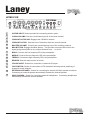
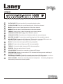
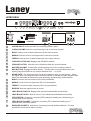
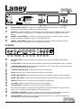
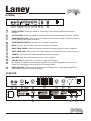
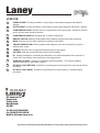
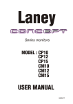
Laney
USER MANUAL
Laney
1
1.
INTRODUCTION
Congratulations on your decision to purchase a Laney amplifier.
Laney products are designed with ease of operation as a primary objective, however to ensure you
derive the best from your new amplifier, it is important you take time to read this user manual and to
familiarise yourself with the control functions and facilities available
BEFORE
SWITCHING ON
After unpacking your amplifier check that it is factory fitted with a three pin 'grounded' (or earthed) plug.
Before plugging into the power supply ensure you are connecting to a grounded earth outlet.
If you should wish to change the factory fitted plug yourself, ensure that the wiring convention applicable to
the country where the amplifier is to be used is strictly conformed to. As an example in the United Kingdom
the cable colour code for connections are as follows.
EARTH OR GROUND - GREEN/YELLOW
NEUTRAL - BLUE
LIVE - BROWN
This manual has been written for easy access of information. The front and rear panels of each unit
are graphically illustrated, with each control and feature numbered. For a description of the function of
each control feature, simply check the number with the explanations adjacent to each panel.
Your Laney amplifier has undergone a thorough two stage, pre-delivery inspection, involving actual
play testing, as well as burn in.
When you first receive your Laney amp, follow these simple procedures:
(I) Ensure that the amplifier is set at the correct voltage for the country it is to be used in.
(ii) Connect your instrument with a high quality instrument cable. Use of cheap cables will compromise
the sound of your instrument and your amplifier.
If there is a problem with your Laney amplifier
DON'T
DO
PHONE YOUR DEALER!
Care of your Laney amplifier will prolong it's life.....and yours!.
Laney
2
HCM30/30R
3
4 5 6
1
Input
1
3
7
4 5 6
7
8 On! 2
2
0
10
9
1
Volume
2
0
10
9
Crunch
clean
factor
3
3
4 5 6
82
4
1
3
7
8
0
10
4 5 6
9
1
Master Max
0
10
Bass
volume
5
6
7
3
4 5 6
82
2
7
9
1
7
3
4 5 6
82
0
10
9
1
7
3
4 5 6
82
0
10
9
1
HCM30R
7
HArdCore Max
0
10
9
0
Mid
Treble
Reverb
CD/Line
In
switch
Foot
External
speaker
phones
8
9
10
11
12
13
14
Equalization
1
8
Head
Power
* Diagram shows HCM30R. HCM30 has identical features apart from reverb
1
GUITAR INPUT: Socket provided for connecting electric guitar...
2
CLEAN VOLUME: Sets the overall listening level of the clean channel.
3
CRUNCH FACTOR ON!: Engages the CRUNCH channel
4
CRUNCH FACTOR: Sets the level of distortion.within the crunch channel..
5
MASTER VOLUME: Controls the overall listening level of the overdrive channel.
6
MAX BUTTON: Engages the MAX feature. This provides a scooped EQ boost to the
signal giving the amplifier a very unique distortion tone......try it out!
7
BASS: Controls the low frequency EQ in the preamplifier.
8
MIDDLE: Controls the mid frequency EQ in the preamplifier.
9
TREBLE: Controls the high frequency EQ in the preamplifier.
10
REVERB: Sets the required level of reverb.
11
CD/LINE INPUT: Sockets for connection of external CD player.
12
FOOTSWITCH: Socket for connection of FS2 footswitch allowing remote switching of
channel & reverb features.
13
EXTERNAL SPEAKER: Socket for connecting an external 4/8 Ohm speaker enclosure.
Connecting an external speaker automatically isolates the internal speaker.
14
HEAD PHONES: Socket for connecting external headphones. Connecting headphones
automatically isolates the internal speaker.
1.
Laney
3
HCM60R
3
4 5 6
7
1
Input
1
3
4 5 6
82
2
0
10
9
1
7
3
4 5 6
82
0
10
clean
Bass
2
3
Volume
9
1
7
3
4 5 6
0
10
Mid
9
1
Equalization
4
3
7
4 5 6
7
8 On! 2
82
0
10
9
1
Treble
0
10
9
Crunch
factor
5
6
3
4 5 6
82
7
1
3
7
8
0
10
4 5 6
9
1
Master Max
0
10
Bass
volume
8
9
7
3
4 5 6
82
2
10
9
1
7
3
4 5 6
82
0
10
9
1
7
3
4 5 6
82
0
10
9
1
HCM60R
7
HardCore Max
0
10
9
0
Mid
Treble
Reverb
CD/Line
In
switch
Foot
External
speaker
phones
11
12
13
14
15
16
17
Equalization
1
8
Head
Power
1
GUITAR INPUT: Socket provided for connecting electric guitar...
2
CLEAN VOLUME: Sets the overall listening level of the clean channel.
3
BASS: Sets the level of bass frequencies in the clean channel.
4
MIDDLE: Sets the level of mid frequencies in the clean channel.
5
TREBLE: Sets the level of high frequencies in the clean channel.
6
CRUNCH FACTOR ON!: Engages the CRUNCH channel
7
CRUNCH FACTOR: Sets the level of distortion.within the crunch channel..
8
MASTER VOLUME: Controls the overall listening level of the overdrive channel.
9
MAX BUTTON: Engages the MAX feature. This provides a scooped EQ boost to the
signal giving the amplifier a very unique distortion tone......try it out!
10
BASS: Controls the low frequency EQ in the preamplifier.
11
MIDDLE: Controls the mid frequency EQ in the preamplifier.
12
TREBLE: Controls the high frequency EQ in the preamplifier.
13
REVERB: Sets the required level of reverb.
14
CD/LINE INPUT: Sockets for connection of external CD player.
15
FOOTSWITCH: Socket for connection of FS2 footswitch allowing remote switching of
channel & reverb features.
16
EXTERNAL SPEAKER: Socket for connecting an external 4/8 Ohm speaker enclosure.
Connecting an external speaker automatically isolates the internal speaker.
17
HEAD PHONES: Socket for connecting external headphones. Connecting headphones
automatically isolates the internal speaker.
1.
Laney
4
HCM120R/H
noise
3
4 5 6
7
Input
1
4 5 6
82
2
1
3
0
10
9
1
7
3
4 5 6
82
0
10
clean
Bass
2
3
Volume
9
1
7
3
4 5 6
10
Mid
9
1
Equalization
4
4 5 6
7
8 On! 2
82
0
3
7
0
10
9
0
10
9
1
6
Gate
8
0
10
3
7
4 5 6
9
1
8
3
4 5 6
82
0
10
Bass
volume
7
7
2
Master Max
Crunch
factor
5
4 5 6
82
1
Treble
3
9
1
7
3
4 5 6
7
82
0
10
9
1
Mid
Equalization
12
9 11
10
3
4 5 6
82
0
10
9
1
Treble
3
7
8
0
10
4 5 6
9
1
8
0
Reverb
14
13
7
2
10
9
Foot
switch
boost
16
17
18
boost
15
Lead
Lead
HCM120R HardCore Max
1
0
Power
008822
WARNING THIS EQUIPMENT MUST BE EARTHED.
CAUTION
RISK OF ELECTRIC SHOCK - DO NOT OPEN
WARNING TO REDUCE THE RISK OF FIRE OR ELECTRIC SHOCK
DO NOT EXPOSE THIS APPLIANCE TO RAIN OR MOISTURE.
CAUTION FOR CONTINUED PROTECTION AGAINST RISK OF
FIRE REPLACE ONLY WITH SAME TYPE AND RATED FUSE.
!
SPEAKER OUTPUT
ATTENTION REMPLACER LE FUSIBLE PAR LE MEME ET LE CALIBRE.
ATTENTION DEBRACHER A LA PRISE SECTEUR AVANT D’OUVRIR.
SUPPLY VOLTAGE
& FUSE RATING
~115V
~230V
T5A
T2A
MAXIMUM POWER CONSUMPTION
200 WATTS ~50/60 Hz
A TOTAL LOAD OF NO LESS THAN
4 OHMS CAN BE CONNECTED AT
ANY ONE TIME
HEAD
PHONES
LINE
OUT
RETURN
SEND
SERIAL No:Made in the United Kingdom by BLT Industries Ltd.
REFER TO USER MANUAL FOR
RECOMMENDED CONNECTIONS.
19
INSERT
20
21
22
23
1
GUITAR INPUT: Socket provided for connecting electric guitar...
2
CLEAN VOLUME: Sets the overall listening level of the clean channel.
3
BASS: Sets the level of bass frequencies in the clean channel.
4
MIDDLE: Sets the level of mid frequencies in the clean channel.
5
TREBLE: Sets the level of high frequencies in the clean channel.
6
CRUNCH FACTOR ON!: Engages the CRUNCH channel
7
CRUNCH FACTOR: Sets the level of distortion.within the crunch channel..
8
MASTER VOLUME: Controls the overall listening level of the overdrive channel.
9
MAX BUTTON: Engages the MAX feature. This provides a scooped EQ boost to the
signal giving the amplifier a very unique distortion tone......try it out!
10
NOISE GATE: .The noise gate only comes into operation once you stop playing. When
the signal level to the amp reduces in sufficient volume to activate the gate, the gate shuts
down and eliminated all extraneous noise producing and absolutely silent amplifier.
11
BASS: Controls the low frequency EQ in the preamplifier.
12
MIDDLE: Controls the mid frequency EQ in the preamplifier.
13
TREBLE: Controls the high frequency EQ in the preamplifier.
14
REVERB: Sets the required level of reverb.
15
LEAD BOOST SWITCH: Engages the onboard footswitchable boost facility.
16
LEAD BOOST LEVEL: Sets the level of the onboard footswitchable boost facility.
17
FOOTSWITCH: Socket for connecting FS2 footswitch enabling the footswitching of
channel and reverb features.
18
LEAD BOOST SOCKET: Socket for connecting FS1 footswitch enabling you to
footswitch the lead boost feature.
19
SPEAKER SOCKETS: Sockets for connecting external speaker cabinets. The total
impedance should not be below 4 Ohms.
1.
Laney
5
008822
1.
WARNING THIS EQUIPMENT MUST BE EARTHED.
CAUTION
RISK OF ELECTRIC SHOCK - DO NOT OPEN
!
WARNING TO REDUCE THE RISK OF FIRE OR ELECTRIC SHOCK
DO NOT EXPOSE THIS APPLIANCE TO RAIN OR MOISTURE.
CAUTION FOR CONTINUED PROTECTION AGAINST RISK OF
FIRE REPLACE ONLY WITH SAME TYPE AND RATED FUSE.
SPEAKER OUTPUT
A TOTAL LOAD OF NO LESS THAN
4 OHMS CAN BE CONNECTED AT
ANY ONE TIME
ATTENTION REMPLACER LE FUSIBLE PAR LE MEME ET LE CALIBRE.
ATTENTION DEBRACHER A LA PRISE SECTEUR AVANT D’OUVRIR.
SUPPLY VOLTAGE
& FUSE RATING
~115V
~230V
T5A
T2A
HEAD
PHONES
LINE
OUT
RETURN
SEND
SERIAL No:-
MAXIMUM POWER CONSUMPTION
200 WATTS ~50/60 Hz
REFER TO USER MANUAL FOR
RECOMMENDED CONNECTIONS.
Made in the United Kingdom by BLT Industries Ltd.
19
INSERT
21
20
22
23
20
HEAD PHONE SOCKET: Socket for connecting external headphones. Connecting
headphones automatically isolates the internal speaker.
21
LINE OUT: Socket provided for connecting to an external power amplifier, Front of house
PA or an external recording device. The signal from this socket is a standard line level
signal.
22
INSERT LOOP RETURN: Socket for connecting the sends of external devices such as
effects processors. Should be used in conjunction with 23.
23
INSERT LOOP SEND: Socket for connecting to the input of external devices such as
effects processors. Should be used in conjunction with 22.
HCM30B
3
4 5 6
8
2
1
0
10
Active
compressor
1
2
3
- 0 +
4
5
4 5 6
5
4
1
7
2
- 0 +
83
0
10
Bass
Sweep
5
6
Gain
4
2 3
32
3
9
Passive
Input
2
7
9
4
Mid
2 2
- 0 +
33
5
5
4
4
4 5 6
32
5
5
Gain
Treble
7
8
Equalization
2 3
4
1
HCM30B
7
HardCore Max
1
8
0
10
Volume
9
9
0
CD/Line
In
Direct
External
speaker
phones
10
11
12
13
out
Head
Power
1
PASSIVE INPUT: Socket provided for connecting a bass guitar equipped with passive
pickups.
2
ACTIVE INPUT: Socket provided for connecting a bass guitar equipped with active pickups.
3
COMPRESSOR GAIN: Sets the level of compression of the input signal. Should be used to
give a punchy bass sound as desired.
4
COMPRESSOR SWITCH: Activates the on board compressor.
5
BASS: Sets the level of bass frequencies present in the signal..
6
SWEPT MID SWEEP: Sets the frequency at which the swept mid gain control is applied.
7
SWEPT MID GAIN: Sets the amount of gain applied to the frequency selected by control 6.
8
TREBLE: Sets the level of high frequencies present in the signal
9
VOLUME: Sets the overall listening volume of the amplifier.
10
CD/LINE INPUT: Sockets for connection of external CD player.
11
DI: Socket provided for connecting the amplifier to an external amplifier such as front of
house PA or providing a direct input into a recording device.
12
EXTERNAL SPEAKER: Socket for connecting an external 4/8 Ohm speaker enclosure.
Connecting an external speaker automatically isolates the internal speaker.
13
HEAD PHONES: Socket for connecting external headphones. Connecting headphones
automatically isolates the internal speaker.
Laney
6
HCM60B
3
4 5 6
1
0
10
Active
compressor
1
2
3
- 0 +
4
2 3
4 5 6
32
3
9
Passive
Input
2
7
8
2
5
5
4
1
2
- 0 +
83
0
10
Bass
Sweep
5
6
9
4
2 2
- 0 +
33
5
Mid
5
4
2 3
4 5 6
32
4
5
5
Gain
Treble
7
8
Equalization
Gain
4
7
4
1
HCM60B
7
HardCore Max
1
8
0
10
Volume
9
9
0
CD/Line
In
Direct
out
phones
10
11
12
Power
Head
1
PASSIVE INPUT: Socket provided for connecting a bass guitar equipped with passive
pickups.
2
ACTIVE INPUT: Socket provided for connecting a bass guitar equipped with active pickups.
3
COMPRESSOR GAIN: Sets the level of compression of the input signal. Should be used to
give a punchy bass sound as desired.
4
COMPRESSOR SWITCH: Activates the on board compressor.
5
BASS: Sets the level of bass frequencies present in the signal..
6
SWEPT MID SWEEP: Sets the frequency at which the swept mid gain control is applied.
7
SWEPT MID GAIN: Sets the amount of gain applied to the frequency selected by control 6.
8
TREBLE: Sets the level of high frequencies present in the signal
9
VOLUME: Sets the overall listening volume of the amplifier.
10
CD/LINE INPUT: Sockets for connection of external CD player.
11
DI: Socket provided for connecting the amplifier to an external amplifier such as front of
house PA or providing a direct input into a recording device.
12
HEAD PHONES: Socket for connecting external headphones. Connecting headphones
automatically isolates the internal speaker.
HCM120B
100Hz
3
4 5 6
1
0
10
Active
compressor
1
2
3
4
Bright
200Hz
800Hz
1K6Hz
5
5
HCM120B HardCore Max
3K2Hz
2
2
- 0 +
3
4
4
5
5
2
2
4
1
Equalization
4
5
7
6
WARNING THIS EQUIPMENT MUST BE EARTHED.
MAXIMUM POWER CONSUMPTION
~115V
T5A
~230V
T2A
EXTERNAL
SPEAKER
MINIMUM 8 OHM
MADE IN THE UNITED KINGDOM BY BLT INDUSTRIES LTD.
ATTENTION REMPLACER LE FUSIBLE
PAR LE MEME ET LE CALIBRE.
CAUTION
TO REDUCE THE RISK OF
FIRE HAZARD REPLACE FUSE WITH
SAME TYPE AND RATING ONLY.
11
8
CAUTION
TO REDUCE THE RISK
OF ELECRIC SHOCK DO NOT REMOVE
COVERS. NO USER SERVICEABLE
PARTS INSIDE. REFER SERVICING
TO QUALIFIED SERVICE PERSONNEL
ATTENTION DEBRANCHER A LA PRISE
SECTEUR AVAVT D'OUVRIR.
3
3
Treble
Bass
Gain
SUPPLY VOLTAGE
& FUSE RATING
400Hz
3
3
9
Passive
Input
2
7
8
2
- 0 +
4 5 6
1
7
8
0
10
9
Volume
9
0
Power
Direct
out
10
CE
SERIAL No:
EFFECTS LOOP
WARNING TO REDUCE THE RISK
OF FIRE OR ELECTRIC SHOCK DO
RETURN
SEND
NOT EXPOSE THIS APPLIANCE TO
RAIN OR MOISTURE.
12
13
Laney
7
HCM120B
1
PASSIVE INPUT: Socket provided for connecting a bass guitar equipped with passive
pickups.
2
ACTIVE INPUT: Socket provided for connecting a bass guitar equipped with active pickups.
3
COMPRESSOR GAIN: Sets the level of compression of the input signal. Should be used to
give a punchy bass sound as desired.
4
COMPRESSOR SWITCH: Activates the on board compressor.
5
BRIGHT SWITCH: Adds top end sparkle and creates a bright punchy bass response.
6
BASS: Sets the level of bass frequencies present in the signal..
7
6 BAND GRAPHIC MID: Allows greater tonal shaping of the mid frequencies to get the
desired bass sound.
8
TREBLE: Sets the level of high frequencies present in the signal
9
VOLUME: Sets the overall listening volume of the amplifier.
10
DI: Socket provided for connecting the amplifier to an external amplifier such as front of
house PA or providing a direct input into a recording device.
11
SPEAKER SOCKET: Socket for connecting external speaker. The external cabinet
cabinet should be no lower than 8 Ohms.
12
EFFECTS LOOP RETURN: Socket for connecting the return signal from an external effects
processor.
12
13
EFFECTS LOOP SEND: Socket for connecting to the input socket of external effects
processor.
BLT Industries LTD.,
Newlyn Road
Cradley Heath
West Midlands
B64 6BE
Tel: (00 44) (0)1384 633821
Fax: (00 44) (0)1384 639186
Web Site http:/www.laney.co.uk
In the interest of continuing product development BLT Industries reserves the right to change specification without prior notice.