1
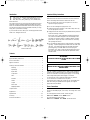
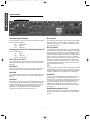
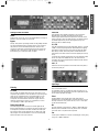
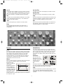
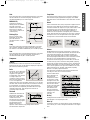
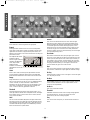
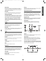
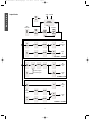
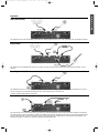
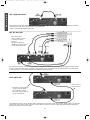
ISA 430 Manual (multilanguage)
20/1/2000
9:08 am
Page 55
ISA430
user’s manual
Focusrite
audio engineering
ISA 430 Manual (multilanguage)
20/1/2000
9:06 am
Page 1
Introduction
Important Safety Instructions
T
Read all of these instructions and save them for future reference.
Follow all warnings and instructions marked on the unit.
hank you for purchasing the ISA430 brought to you by the
Focusrite team – Trevor, Peter, Martin, Helen, Tom,
Mick, Phil, Chris, Micky, Pauline, Jo, Chris, Nathan, Rob,
Peter and Simon.
The chaps at Focusrite are a jolly hard working bunch and take a
great deal of pride in designing, building and delivering products
which are considered the best audio units around; we hope your
new Focusrite unit lives up to that reputation and that you enjoy
many years of productive recording.
If you would like to tell us about your recording experiences then
email us at: [email protected]
●
Do not obstruct air vents in the rear panel. Do not insert
objects through any apertures.
●
Do not use a damaged or frayed power cord.
●
Unplug the unit before cleaning. Clean with a damp cloth only.
Do not spill liquid on the unit.
●
Unplug the unit and refer servicing to qualified service personnel
under the following conditions:
If the power cord or plug is damaged; if liquid has entered the
unit; if the unit has been dropped or the case damaged; if the
unit does not operate normally or exhibits a distinct change in
performance. Adjust only those controls that are covered by
the operating instructions.
●
The Focusrite Team
Do not defeat the safety purpose of the polarised or groundingtype plug. A polarised plug has two blades with one wider than
the other. A grounding type plug has two blades and a third
grounding prong. The wider blade or the third prong are
provided for your safety. When the plug provided does not fit
into your outlet, consult an electrician for replacement of the
obsolete outlet.
Contents
WARNING:
THIS UNIT MUST BE EARTHED BY THE POWER
CORD
Important Safety Instructions . . . . . . . . . . . . . . . . . . . . . . . . . . . . . .1
Power Connections . . . . . . . . . . . . . . . . . . . . . . . . . . . . . . . . . . . . .1
Signal Connections . . . . . . . . . . . . . . . . . . . . . . . . . . . . . . . . . . . . . .2
UNDER NO CIRCUMSTANCES SHOULD THE
MAINS EARTH BE DISCONNECTED FROM THE
MAINS LEAD.
Getting to Know the ISA430 . . . . . . . . . . . . . . . . . . . . . . . . . . . . . .3
Metering . . . . . . . . . . . . . . . . . . . . . . . . . . . . . . . . . . . . . . . . . . .3
Input Stage . . . . . . . . . . . . . . . . . . . . . . . . . . . . . . . . . . . . . . . . .3
Gate . . . . . . . . . . . . . . . . . . . . . . . . . . . . . . . . . . . . . . . . . . . . . . .6
This unit is capable of operating over a range of mains voltages as
marked on the rear panel. Ensure correct mains voltage setting
and correct fuse before connecting mains supply. Do not change
mains voltage settings while mains supply is connected.
De-Esser . . . . . . . . . . . . . . . . . . . . . . . . . . . . . . . . . . . . . . . . . . .6
To avoid the risk of fire, replace the mains fuse only with the
correct value fuse, as marked on the rear panel.
EQ Module . . . . . . . . . . . . . . . . . . . . . . . . . . . . . . . . . . . . . . . . .4
Compressor . . . . . . . . . . . . . . . . . . . . . . . . . . . . . . . . . . . . . . . .5
Limiter . . . . . . . . . . . . . . . . . . . . . . . . . . . . . . . . . . . . . . . . . . . . .7
The internal power supply unit contains no user serviceable parts.
Refer all servicing to a qualified service engineer, through the
appropriate Focusrite dealer.
Output . . . . . . . . . . . . . . . . . . . . . . . . . . . . . . . . . . . . . . . . . . . . .7
Stereo A/D . . . . . . . . . . . . . . . . . . . . . . . . . . . . . . . . . . . . . . . . .7
Power Connections
Single/Split Mode . . . . . . . . . . . . . . . . . . . . . . . . . . . . . . . . . . . . .7
There is an IEC mains lead supplied with the unit which should have
the correct moulded plug for your country. The wiring colour code
used is:
Output Modes . . . . . . . . . . . . . . . . . . . . . . . . . . . . . . . . . . . . . . . . . .8
Applications . . . . . . . . . . . . . . . . . . . . . . . . . . . . . . . . . . . . . . . . . . . .9
Specifications . . . . . . . . . . . . . . . . . . . . . . . . . . . . . . . . . . . . . . . . . .51
For units shipped to the USA, Canada, Taiwan and Japan:
Warranty . . . . . . . . . . . . . . . . . . . . . . . . . . . . . . . . . . . . . . . . . . . . .51
Live - Black Neutral - White Earth - Green
Focusrite Distributors . . . . . . . . . . . . . . . . . . . . . . . . . . . . . . . . . .52
For units shipped to any other country:
Live - Brown Neutral - Blue Earth - Green and Yellow
1
E
N
G
L
I
S
H
ISA 430 Manual (multilanguage)
E
N
G
L
I
S
H
20/1/2000
9:06 am
Page 2
Signal Connections
Optional A/D Card shown
XLR (Audio) Inputs and Outputs
INT A/D Direct
All 3-pin XLR audio connectors (Outputs, Mic/Line Inputs, Insert Send
& Return) are wired as follows:
The ‘Internal A/D Direct’ input is used to route an external signal
directly to the A/D card via the Limiter. It replaces the ‘Internal’
signal feed to the A/D card (i.e. whatever is connected to the mic,
line or instrument input.)
Pin 1
Screen/Chassis
Pin 2
Audio 0°
Pin 3
Audio 180°
EXT IP A/D Direct
The External A/D Direct input is used to route an external signal
to the optional A/D card via the Limiter. The signal is normally fed
to the “spare” side of the A/D card not being used by the internal
signal, and so does not replace it. However it is possible to also
sum the External A/D Direct input together with the main internal
signal, (i.e. whatever is connected to the mic, line or instrument
input,) using the ‘sum’ button on the front panel. This will result in
whatever is connected to the External A/D Direct input being
routed to both sides of the A/D converter. For example, a reverb
signal could be processed externally and then be summed with a
dry snare drum signal in this way.
Instrument Input, Key IPS, Int A/D Direct and Dynamic Link
1/4” Jack wired as follows:
Tip
Audio 0°
Ring
Audio 180°
Sleeve
Screen/Chassis
Mic IP/Line IP/Inst. Hi Z IP
Any one of these inputs may be used as the main input to the ISA430.
Signals routed to these inputs are referred to as the ‘internal’ or ‘Int’
signal path.
OP1
Insert Return
This output is used as the main analogue internal signal output, and
is fed by whatever is connected to the mic IP, Line IP or Inst. Hi Z
IP, aftyer this signal has been routed through the EQ and dynamics
modules (in ‘single’mode) or through EQ only (in ‘split’ mode.)
This is used as the insert input point, or as the input to the dynamics
modules in ‘split mode’ (see ‘Dynamics Split’ diagram on page 7.)
Insert Send
Dynamic Link
This is used as the insert output point, or as the analogue output from
the dynamics module in ‘split mode’ (see ‘Dynamics Split’ diagram on
page 7.)
You can connect two ISA430 units (using a standard stereo jack to
jack lead between the DYNAMIC LINK sockets) to allow the
dynamics sections to behave as a stereo pair of processors. When
connected in this way the dynamics processors behave as if both
units were receiving the same level of signal, with both units
responding to the higher level of the two signal paths. The EQ
channels can be matched visually or aurally to be used as a stereo
pair if required.
Post Mic OP
This is used as an output from the point immediately after the mic pre
(i.e. before EQ and dynamics modules.) It is used as a direct-to-tape
ultra-short signal path output. Taking a signal from this ‘post mic OP’
does NOT interrupt the signal flow from the mic pre to the EQ,
dynamics etc., so a direct feed to tape can be achieved, whilst
simultaneously allowing processing of the same source.
Retrofitting the Optional A/D Card
The optional A/D card can be retrofitted to a standard ISA430 at
any time. Full fitting instructions for this option are included with
the Card.
2
ISA 430 Manual (multilanguage)
20/1/2000
9:06 am
Page 3
E
N
G
L
I
S
H
Getting to Know the ISA430
Listen LED
This illuminates when LISTEN is selected on the Compressor,
Expander/Gate or De-Esser and indicates that the unit is
monitoring the selected side chain frequencies. Note that the VU
meter continues to show the signal chosen by VU SELECT and not
the LISTEN signal. What you are watching and what you are
hearing can be two different things!
Power
Applies power to the unit. Turn on the ISA430 before powering up
devices to which the outputs are connected.
Bypass
The EQ and Dynamics processing modules can be globally switched
out using the BYPASS switch, providing a direct route (except for
the protection of the multi-band limiter which remains in the
circuit) from Line Input or External Input to the A/D inputs. This
enables the unit to be used as a 24 bit, 96k stereo converter for
final mastering or for analogue transfer to digital.
O/L LED
This LED illuminates when the peak signal level reaches or exceeds
+20dB, or when the peak signal level reaches 6dB below clipping.
The signal is monitored at four points: after the input gain TRIM,
after the EQ module, after the Dynamics module and after the
Insert Return, since each module could cause clipping if incorrectly
set up.
Occasional short-duration peaks which may cause the LED to blink
will not normally cause audible distortion, but if the LED is lit
constantly, the level in the appropriate module should be reduced
to prevent overloading.
Inst I/P
Instrument sources may either be connected via the rear panel, or
via this front panel jack.
Input Stage
Metering
Three input options are provided to give compatibility with Mic,
Line or Instrument sources.
VU Select
An immediately-post-mic pre balanced output (“Post Mic OP”)is
provided on the rear panel giving an ultra-short signal path to allow
for the cleanest possible recordings.
The VU Meter can display input level, insert return level, or the
compressor gain reduction. Press VU SELECT to step through the
three sources as indicated by the corresponding LEDs. For the
Input and Insert Return, 0VU corresponds to +4dBu. For the
Compressor the meter indicates the amount of gain reduction
caused by compression, from 0VU (no compression) to -20VU
(corresponding to 20dB of gain reduction).
Select
Pressing SELECT steps through each of the three inputs as
indicated by the corresponding LEDs. When the Mic LED is lit, the
Mic input is active etc. Only one of the ‘Mic’, ‘Line’ or ‘Inst’ inputs
can be used simultaneously.
Digital Output Meters
Mic
Two LED bargraph meters monitor the Internal signal and the
External signal (whatever is connected to the “Ext I/P A/D Direct”
XLR input) at a point after the Limiter but before the A/D input.
The meters provide a wide range with the O/L LED (lower right
side) acting as an Overload indicator to warn of excessively high
levels at the input of the A/D converters.
Mic input sensitivity is switched from -60dB to +6dB in 6dB steps.
Phantom power is available on the rear panel XLR for condenser
mics when +48V front panel switch is pressed.
Line
A Line input is available on XLR, with a switched gain control giving
a range of +/-18dB in 6dB steps.
3
ISA 430 Manual (multilanguage)
E
N
G
L
I
S
H
20/1/2000
9:06 am
Page 4
Inst I/P
Low Pass Filter
An Instrument input is available on 1/4” jacks on either rear panel
or front panel. This is suitable for high impedance sources such as
guitars or bass pickups (which may be connected directly without
the need for a DI box), or synthesisers with low level outputs.
A variable control sets a rolloff frequency from 400Hz to 22kHz.
Trim
Comp
The TRIM control provides additional variable gain of 0 to +20dB
for MIC and LINE inputs (white legend), or 0 to +40dB for the
Instrument input (yellow legend).
When the COMP switch is pressed both filters are inserted in the
Compressor sidechain for frequency-selective compression. This
selection is cancelled if FILTER IN or GATE is pressed.
+48V
Gate
Provides +48V powering for condenser mics when pressed.
When the GATE switch is pressed both filters are inserted in the
Gate sidechain to assist accurate drum gating. This selection is
cancelled if FILTER IN or COMP is pressed.
High Pass Filter
A variable control sets a rolloff frequency from 20Hz to 1k6Hz.
Phase
Pressing PHASE reverses the phase of the selected input, to
correct phase problems with close microphones or incorrect
wiring polarity.
PARAMETRIC EQ
EQ Module
Two separate bands of parametric EQ are provided, each with
continuously variable boost/cut with centre detent, sweep control
with two ranges, and variable Q. The first band covers the range
40Hz to 400Hz (120Hz to 1k2Hz when x3 is pressed) and the
second band covers 600Hz to 6kHz (1.8kHz to 18kHz when x3 is
pressed).
All EQ
Pressing ALL EQ activates all sections of the EQ module (including
the Hi and Lo Pass Filters), placing the whole module in the audio
path. Toggling ALL EQ allows A/B comparison of EQ settings
without having to use BYPASS which switches both EQ and
Dynamics modules in or out of the audio path. The COMP and
GATE switches on individual EQ sections (see below) operate
independently from the ALL EQ switch.
Param EQ In
Press in to switch the
Parametric EQ into the
signal path. This selection is
cancelled if GATE or
COMP is pressed.
Filter In
Press in to make the Hi and Lo Pass Filters active in the audio path.
This selection is cancelled if COMP or GATE is pressed.
x3
Both filters provide
18dB/octave rolloff, and
since the filter
frequencies overlap they
may be configured as a
very tight bandpass filter
for creative compression
and gating; use when you
wish to select a specific
instrument or narrow
frequency band from a complex signal, then feed to the sidechain of
the compressor or gate.
The Sweep controls have
two ranges, the higher being selected when the x3 switch is
pressed (frequencies shown in yellow on the panel).
Comp
When the COMP switch is pressed, the Parametric EQ is inserted
in the Compressor sidechain allowing frequency-selective
compression. This selection is cancelled if PARAM EQ IN or GATE
is pressed.
4
ISA 430 Manual (multilanguage)
20/1/2000
9:06 am
Page 5
Gate
Comp Listen
When the GATE switch is pressed the Parametric EQ is inserted in
the Gate sidechain for accurate drum gating. This selection is
cancelled if PARAM EQ IN or COMP is pressed.
Press to allow audio monitoring of the compressor sidechain to
assist accurate frequency adjustment during setup. The LISTEN
LED beside the VU meter illuminates to show that ‘Listen’ mode is
active.
SHELVING EQ
Attack
High and Low frequency
shelving sections are available,
each with continuously
variable boost/cut with centre
detent, and a six position
rotary switch for selection of
rolloff frequency.
ATTACK determines how quickly compression is applied once the
level of the source signal has risen above the Threshold. When
turned anticlockwise the response is very fast, which tends to make
the compressor react to the peak levels of the signal. This is
sometimes desirable, but can cause unwanted “pumping” of
steadier low level components of the signal by short transients. A
slower attack will cause the compressor to ignore short transients
and respond more to the average loudness of the signal; however
this may seem to increase relative volume of the transients.
Shelving EQ In
Press in to switch all the
Shelving EQ into the signal
path. This selection is
cancelled if GATE or COMP is
pressed.
Comp
When the COMP switch is pressed the Shelving EQ is inserted in
the Compressor sidechain for frequency-selective compression.
This selection is cancelled if SHELVING EQ IN or GATE is pressed.
Release
Gate
RELEASE determines how quickly compression is removed once
the level of the source signal has fallen below the Threshold. When
in the anticlockwise position, the compression releases very
quickly, which may be appropriate on rapidly varying signals to
avoid compressing the beats that follow, but can result in excessive
distortion on more sustained material. Clockwise rotation
increases the release time, giving a smoother effect, but which at
the same time may result in transients causing audible “pumping”.
When the GATE switch is pressed the Parametric EQ is inserted in
the Gate sidechain for accurate drum gating. This selection is
cancelled if SHELVING EQ IN or COMP is pressed.
Compressor
Comp In
Rotation fully clockwise switches release to AUTO, substituting an
adaptive attack/release circuit which essentially varies the release
rate to suit the dynamics of the signal. This enables the use of fast
attack times without any “pumping” type artefacts, especially
effective on complex programme material.
Press COMP IN to switch the compressor into the signal path.
Note that the VU meter can be selected to display the compressor
gain reduction (see Metering section).
Ratio
The release rate is probably the most important variable when
recording rock music, since it controls loudness.
The RATIO control determines
the rate at which compression
is applied to the signal with
increasing input, and is the ratio
of change in input level
compared to change in output
level. The control gives a range
of 1.5 to 10. Higher Ratio
settings will produce more noticeable compression, so for the least
obtrusive result, the Ratio should be set at the minimum necessary
for the application. For example, using low Threshold and low
Ratio will produce less subjectively noticeable effect than a high
threshold and high ratio, even though the total amount of
compression may be the same.
Loudness is determined
by the maintenance of
high mean levels:
compression increases
the proportion of highlevel signal content, and
as the diagram shows, the
faster the unit releases,
the more low-level signal
is brought to a higher
level. Therefore, the
faster the release rate,
the higher the perceived
loudness of the
recording.
Threshold
THRESHOLD determines the
level at which compression
begins, with a range -28dB to
+12dB. The lower the
Threshold, the more the signal
is compressed. Setting a higher
Threshold allows quieter
passages in the music or
speech to remain unaffected; only passages that exceed the
Threshold will be compressed.
Ext Key
Pressing EXT KEY switches control of the compressor to an
external signal on a rear panel jack socket.
Make Up
Compression results in an overall reduction in level. The MAKE UP
control allows you to restore the signal volume back to the original
level.
5
E
N
G
L
I
S
H
ISA 430 Manual (multilanguage)
20/1/2000
9:06 am
Page 6
E
N
G
L
I
S
H
GATE
Release
This control sets the Release time, the rate at which the gate
attenuation increases, fading out the signal: this Release period
begins immediately the signal has dropped below the Threshold.
On transient signals a fast release will be appropriate (control
anticlockwise), but with other material a slower release (control
clockwise) may give a more natural sound. Ideally the Release
needs to be slightly slower than the natural decay rate of the signal
to avoid audibly cutting it short.
Gate In
Press GATE IN to switch the gate into the signal path.
Expand
Pressing EXPAND causes the Gate to function as an Expander,
which gives a similar effect to gating, but instead of cutting off any
signal below the threshold, it proportionately decreases it (see
diagram). This may give a more natural sound when recording non-
Fast Attack
percussive sources.
The adjacent LED meter
indicates in dB the
amount of gain reduction
caused by the Expander
Gate, and provides
additional visual
indication of the effect of
the RANGE control (see
below).
FAST ATTACK determines how quickly the gate opens once the
level of the source signal has risen above the threshold. When the
switch is pressed, the response is fast, which may be necessary on
some signals to avoid “missing” an initial transient, but could also
introduce an undesirable click on smooth, sustained sounds when
using a high threshold setting. On such signals a slower attack
(switch released) may give a more natural sound.
Hyst
Press to introduce hysteresis; this will prevent the gate oscillating
with particular combinations of input signal and threshold settings.
Listen
Ext Key
Press to allow audio monitoring of the gate sidechain to assist
accurate frequency adjustment during setup. The LISTEN LED
beside the meter illuminates to show that ‘Listen’ mode is active.
Pressing EXT KEY switches control of the gate to an external signal
on a rear panel jack socket.
Range
De-Esser
Range determines how much the signal is attenuated when the
Gate is closed. The Gate can be set up as a cut (80dB attenuation,
control clockwise) or lesser attenuation to 0dB. Maximum
attenuation may give an unnatural sound, so keep Range at a low
value unless it is essential to reduce high levels of background
noise, or unless an obviously gated effect is desired.
The DE-ESSER is based on an optical technology design, letting you
remove excessive sibilance from a vocal performance (if “ess”
sounds are over-emphasised).
De-Ess In
Press in to activate the De-Esser.
Threshold
Threshold
Threshold determines the level at which the gate opens, (or at
which gain reduction finishes when in Expander mode.) The higher
the threshold, the more the low-level noise is reduced, and the
more extreme the effect.
THRESHOLD determines how much de-essing is being applied to
the selected frequency. The lower the threshold (control
anticlockwise), the more de-essing is applied.
Hold
Freq
HOLD controls the variable delay before the gate release starts.
This allows the Gate to be held open until the signal has decayed
away sufficiently that the quite rapid onset of gain reduction isn’t
noticeable: alternatively the signal can be deliberately truncated
before its natural end for special effects.
This control selects a frequency to remove between 2k2Hz and
9k2Hz.
6
ISA 430 Manual (multilanguage)
20/1/2000
9:06 am
Page 7
De-Ess Listen
Ext Sync
Press to allow monitoring of only the signals which will trigger
activation of the De-Esser rather than hearing the overall effect in a
complex signal. The LISTEN LED beside the meter illuminates to
show that ‘Listen’ mode is active.
Press to select the EXT SYNC input on the rear panel. This allows
theISA430 to be slaved to external wordclock.
Single/Split Mode Selection
Active LED
The unit can be run as a single channel “Producer Pack”, or split to
act as two independent processors running discrete audio paths.
This LED illuminates when the De-Esser is active at the chosen
frequency, and shines brighter with increasing level reduction.
Split mode allows the INSERT SEND and INSERT RETURN
connections to act as independent inputs and outputs to the
dynamics section only, creating two devices in one, with separate
EQ and Dynamics; perfect for mix down.
Setting up the De-Esser
Press DE-ESS LISTEN with THRESHOLD at maximum and slowly
reduce until the selected frequency begins to trigger the De-Esser.
Vary the frequency control to find the exact area of the signal
which you wish to remove. Once located, switch off DE-ESS
LISTEN and adjust THRESHOLD for the amount of reduction
required. No further adjustment of FREQUENCY should be
required, as the hot spot will have been more precisely found using
DE-ESS LISTEN.
Dynamics Pre Eq
Normally the EQ section is first in the signal path. Pressing PRE EQ
reverses the position of the EQ and Dynamics sections, placing
Dynamics first and EQ afterwards.
Split Dynamics
Press SPLIT DYNAMICS to separate the EQ and Dynamics
sections, creating two independent modules as shown below.
LIMITER
Limit In
Press to activate the multi-band limiter. Three separate fixed
frequency bands with different limiting properties give true
distortion-free limiting.
Active LED
This LED illuminates when the Limiter is active. An upper threshold
is fixed at +20dBu to prevent overload of the internal (or an
external) A/D converter.
Output
Sum
Insert In
Press to route both the internal signal and external line input signal
(from the “EXT I/P A/D DIRECT” rear panel jack) to the module
output. (External signals could be a double track, an extra mic from
a second ISA430 or live reverb.)
Normally the insert is bypassed. Pressing INS IN places the insert
in the audio path in the selected position.
Insert Position
External
The Insert Send and Return may be positioned in three places
within the unit for maximum versatility, as shown in the diagram.
Pressing the INSERT POSITION switch steps through the three
options, as indicated on the corresponding LEDs.
This control adjusts the gain of the external line input, which may
be summed into the module output (see above).
Output
The options are PRE (Insert is after the input Trim, but before EQ
or Dynamics, (depending on the setting of the DYNAMICS PRE EQ
switch)), MID (between EQ and Dynamics) or POST (after EQ and
Dynamics and before the main output).
A variable control adjusts the module output level (OP1) between
-60dB and +6dB.
Mute
Press to mute the output from the unit.
Stereo A/D
The ISA430 can be used as a high quality stereo converter channel
for final mastering, or for analogue transfer to digital (by adding the
optional ISA430 digital output board.) The external input, and the
line input (when BYPASS is pressed) are both fed to the A/D
inputs, via the limiter, giving a clean, protected, high quality path to
digital. Converter settings are as follows:
Clock Select
Selectable between 44.1kHz, 48kHz, 88.2kHz and 96kHz.
Bit Rate Select
Selectable between 24, 20 and 16 bits.
7
E
N
G
L
I
S
H
ISA 430 Manual (multilanguage)
E
N
G
L
I
S
H
20/1/2000
9:06 am
Page 8
Output Modes
SEND RETURN
POST
MIC
O/P
INSERT
SWITCHING
PRE
POST
MID
INPUT
SELECTION
LEVEL
TRIM
&
PHASE
MIC
LINE
INST
EQ
DYNAMICS
FILTERS
SHELF
PARAM
COMP
GATE
&
DE-ESS
SWAP WITH DYNAMICS PRE EQ
Transformer
O/P
LEVEL
LIMITER
METER
O/P
OP1
Analogue
Out
A/D
CARD
Digital
Out
Int
EXT
I/P
LIMITER
METER
Ext
O/P MODE 1 - STANDARD
Transformer
O/P
LEVEL
EXT
I/P
SUM
LIMITER
METER
Mix External Signal
into Internal Signal
O/P
OP1
Analogue
Out
A/D
CARD
Digital
Out
O/P MODE 2 - SUM
Transformer
O/P
LEVEL
INT
DIRECT
TO A/D
EXT
I/P
LIMITER
LIMITER
O/P
OP1
Analogue
Out
A/D
CARD
Digital
Out
METER
METER
O/P MODE 3 - A/D DIRECT
8
ISA 430 Manual (multilanguage)
20/1/2000
9:07 am
Page 9
Applications
E
N
G
L
I
S
H
Super Clean Recording
This example shows the shortest possible (lowest distortion) analogue signal path from mic to tape. It bypasses all EQ and Dynamics functions.
Record Channel
This example shows the ISA430 being used for mic or guitar recording. The insert point may be used to add external processing ‘in-line’ if
required.
Record Digital with ‘O/P Transformer’ in circuit *
This example shows how to record from Mic (or Line/Inst inputs) to the A/D, routing the audio through the output transformer. (In normal
use, the “Int A/D Direct” input feeds the limiter and meter, then routing directly to the A/D card.)
* Requires optional ISA430 Digital Output Board
Stereo A/D Converter
The optional A/D card is a stereo device which can convert two tracks simultaneously. Stereo conversion can be accessed by connecting the
two audio signals into the EXT A/D DIRECT and INT A/D DIRECT inputs (directly accessing the A/D inputs via the limiter and digital meters).
The INT input of the A/D can also be connected in the normal way via the Line I/P, if additional mono processing (EQ and Dynamics) were
required on the signal, or if dual mono signals were being converted simultaneously.
9
ISA 430 Manual (multilanguage)
E
N
G
L
I
S
H
20/1/2000
9:07 am
Page 10
Split + Digital Record Mode *
This example shows the insert send feeding the “External I/P A/D Direct” input. This allows an analogue input to be connected to the insert
return, and then routed, via the dynamics modules, to the digital output.
* Requires optional ISA430 Digital Output Board.
Split ‘Mix Down Mode’
Switch unit to SPLIT.
Insert 2 channels of console,
one as EQ, the other as
Dynamics.
Mix down to digital using
ISA430 A/D and Limiter section
for high quality digital master
This example shows how to use the ISA430 in split mode as a mixdown tool. The ISA430 is simultaneously allowing EQ processing on audio
from the console (CH1) and Dynamics processing on audio fromthe console (CH2) and allowing A/D digital conversion of the final mix fed
from the master L/R console outputs. (Requires optional ISA430 Digital Output Board.)
Stereo ISA430 Units
A/D Card fitted
Stereo control of
Dynamics section
Send audio from second ISA430
to A/D Card in first ISA430.
This configuration creates a
stereo record channel with only
one A/D Card required.
No A/D Card fitted
This example shows how to link two ISA430s together, allowing them to be used as a stereo record channel. (Stereo dynamics processing and
dual mono EQ (can be used as a stereo channel.)) The stereo channel can then be routed to a single optional ISA430 Digital Output Board
allowing A/D conversion of the stereo signal.
10
ISA 430 Manual (multilanguage)
20/1/2000
Specifications
Rear Panel Connectors
Insert Send
Connector:
Signal:
Operating Level:
Maximum O/P Level:
XLR
Balanced
+4dBu
+26dBu
This output has two modes of operation:
INSERT IN, the connector is an output from
the point in the signal path determined by the
Pre, Mid and Post selector and the Dyn Pre
EQ button.
SPLIT, the connector is the output of the
dynamics section of the module.
Page 51
Input Impedance:
Noise:
THD:
10KΩ
-96dBu
0.003% with 0dBu
1kHz input and
20Hz-22kHz
bandpass filter
Mic
Connector:
Signal:
Operating Level:
Maximum I/P Level:
Gain Range:
XLR
Balanced(Transformer)
+4dBu
+26dBu
-6 to +60dB
in 6dB steps
1k2Ω
123dB EIN with 150Ω
Input Impedance:
Noise:
input resistance
at 60dB of gain
0.0008%
THD:
Insert Return
Connector:
Signal:
Operating Level:
Maximum I/P Level:
9:08 am
XLR
Balanced
+4dBu
+26dBu
This input has two modes of operation:
Post Mic OP
Connector:
Signal:
Operating Level:
Maximum O/P Level:
XLR
Balanced
+4dBu
+26dBu
INSERT IN, the connector is the return or
input to the signal path determined by the
Pre, Mid and Post selector and the Dyn Pre
EQ button.
Signal is routed directly from the Preamp
after the gain stage, trim and phase reverse
circuits of the input section and can be fed
from the Mic, Line or Instrument
SPLIT, the connector is the input nto the
dynamics section of the module.
OP1
Inst. Hi Z I/P
Connector:
Mono Jack
Signal:
Unbalanced
(from any high impedance source such as
guitar or bass pickups)
Operating Level:
-10dBu
Maximum I/P Level: +10dBu
Gain Range:
+10 to +40dB
Input Impedance:
>1MΩ
Line
Connector:
Signal:
Operating Level:
Maximum I/P Level:
Gain Range:
XLR
Balanced
+4dBu
+26dBu
+/-18dB in 6dB steps
Connector:
Signal:
Operating Level:
Maximum O/P Level:
XLR
Balanced (Transformer)
+4dBu
+26dBu
Signal is the transformer output stage.
Ext A/D Direct I/P
Connector:
Signal:
Operating Level:
Maximum I/P Level:
XLR/Jack
Balanced
+4dBu
+22dBu=0dBFs
Int A/D Direct I/P
Connector:
Signal:
Maximum I/P Level:
TRS (Stereo) Jack
Balanced
+22dBu=0dBFs
Accuracy:
Warranty:
Whilst every effort has been made to ensure
the accuracy and content of this manual,
Focusrite Audio Engineering Ltd makes no
representations or warranties regarding the
contents.
All Focusrite products are covered by a
warranty against manufacturing defects in
material or craftsmanship for a period of one
year from the date of purchase. Focusrite in
the UK, or its authorised distributor
worldwide will do its best to ensure that any
fault is remedied as quickly as possible. This
warranty is in addition to your statutory rights.
Copyright:
Copyright January 1999 Focusrite Audio
Engineering Ltd. All rights reserved. No part of
this manual may be reproduced, photocopied,
stored on a retrieval system, transmitted or
passed to a third party by any means or in any
form without the express prior consent of
Focusrite Audio Engineering Ltd.
This warranty does not cover any of the
following:
• Carriage to and from the dealer or factory
for inspection or repair labour charge if
repaired other than by the distributor in the
country of purchase or Focusrite in the U.K.
51
Inserting the jack breaks the connection of
the A/D input from the signal path and routes
the signal from the jack directly to the A/D
(Via the meter and limiter).
Gate Key I/P + Comp Key I/P
Connector:
Signal:
Operating Level:
Maximum I/P Level:
TRS (Stereo) Jack
Balanced
+4dBu
+26dBu
Drives the sidechain of the gate or
compressor.
Dynamic Link
Links two ISA430 units and control the
dynamics section of both from one unit giving
accurate stereo dynamics control.
Compressor
Threshold Range:
Ratio:
Slope:
Attack:
Release:
-28dB to +12dB
1.5:1 to 10:1
Soft knee
100µS to 100mS
100mS to 4S,
variable or auto
(program dependent)
Limiter
Threshold Range:
Ratio:
Attack:
22dBu
∞ (infinity)
Fast
Gate
Threshold Range:
Gate Range:
Attack:
Release:
Hold:
Expander Ratio:
-40dB to +10dB
0 to -80dB
switched fast or slow
100mS to 5S
20mS to 4S
0 to 5:1
De-Esser
Threshold Range:
Frequency Range:
Ratio at Centre
Frequency
22dBu
2K2 to 9K2
2:1
• Consequential loss or damage, direct or
indirect, of any kind, however caused
• Any damage or faults caused by abuse,
negligence, improper operation, storage or
maintenance
If a product is faulty, please first contact your
dealer in the country of purchase;
alternatively, contact the factory. If the
product is to be shipped back, please ensure
that it is packed correctly, preferably in the
original packing materials. We will do our best
to remedy the fault as quickly as possible.
Please help us to serve you better by
completing and returning the Warranty
Registration Card at the back of this manual.
Thank you.
ISA 430 Manual (multilanguage)
20/1/2000
9:08 am
Page 52
Focusrite Distributors
Argentina
Phone:
Fax:
Australia
Phone:
Fax:
Austria
Phone:
Fax:
Belgium
Phone:
Fax:
Brazil
Phone:
Fax:
Canada
Phone:
Fax:
Chile
Phone:
Fax:
Croatia, Slovenia,
Bosnia, Macedonia
and Serbia
Phone:
Fax:
Denmark
Phone:
Fax:
Egypt
Phone:
Fax:
Finland
Phone:
Fax:
France
Phone:
Fax:
Germany
Phone:
Fax:
Greece
Phone:
Fax:
Hong Kong/China
Phone:
Fax:
Iceland
Phone:
Fax:
India
Phone:
Fax:
Indonesia
Phone:
Fax:
Ireland
Phone:
Fax:
Israel
Phone:
Fax:
Italy
Phone:
Fax:
Japan
Phone:
Fax:
Korea
Phone:
Fax:
DBA Systems SRL
00 54 1 545 6800
00 54 1 545 3668
Electric Factory Pty Ltd
00 61 3 9480 5988
00 61 3 9484 6708
TC Electronic Austria
0800 201 652
0800 201 653
EML
00 32 11 23 23 55
00 32 11 23 21 72
Proware
00 55 11 5585 2866
00 55 11 5584 6586
Sonotechnique Inc
00 1 416 947 9112
00 1 416 947 9369
Clio Musical Productora
00 56 2 274 9621
00 56 2 294 9575
R. O. Maldives
Phone:
Fax:
Mexico
Phone:
Fax:
Netherlands
Phone:
Fax:
New Zealand
Phone:
Fax:
Norway
Phone:
Fax:
Poland
Phone:
Fax:
Portugal
Phone:
Fax:
Russia
Phone:
Fax:
Singapore
Music Export
00 49 89 746 123 90
00 49 89 746 123 92
New Music AG
00 45 86 190899
00 45 86 193199
Alpha Audio
00 202 245 6199
00 202 247 8969
Studiotec Ky
00 358 9 5123 5330
00 358 9 5123 5355
DM2J Audio Solution
00 33 1 48 63 04 43
00 33 1 48 63 02 01
TC Electronic
00 49 40 531 08 399
00 49 40 531 08 398
Bon Studio S.A.
00 30 1 3809605-8
00 30 1 3827868
Digital Media Technology
00 852 2721 0343
00 852 2366 6883
Exton
00 354 551 2555
00 354 562 6490
R & S Electronics
00 91 22 636 9147
00 91 22 636 9691
Paradi
00 6221 831 8388
00 6221 8370 3473
CTI - Control Techniques Ireland
00 353 1 454 5400
00 353 1 454 5400
Sontronics
00 972 3 570 5223
00 972 3 619 9297
Grisby Music Professional
00 39 0 71 7108471
00 39 0 71 7108477
All Access Inc
00 81 52 443 5537
00 81 52 443 7738
Best Logic Sound Co
00 82 2 515 7385
00 82 2 516 7385
Phone:
Fax:
South Africa
Phone:
Fax:
Spain
Phone:
Fax:
Sri Lanka
Phone:
Fax:
Sweden
Phone:
Fax:
Switzerland
Phone:
Fax:
Taiwan
Phone:
Fax:
Thailand
Phone:
Fax:
Turkey
Phone;
Fax:
United Kingdom
Phone:
Fax:
USA
Phone:
Fax:
Phone:
Fax:
Venezuela
Phone:
Fax:
Vietnam
Phone:
Fax:
52
Island Acoustics
00 960 32 0032
00 960 31 8624
Vari
00 525 604 6946
00 525 605 9656
Total Audio BV
00 31 20 4476447
00 31 20 4476464
Protel
00 64 4 801 9494
00 64 4 384 2112
Lydrommet
00 47 22 80 94 50
00 47 22 80 94 60
Hexagon
00 48 22 44 66 99
00 48 22 44 83 55
Caius Tecnologias
00 351 2 208 6009
00 351 2 208 5969
AT Trade
00 7 095 956 1105
00 7 095 956 6882
Team 108 Technical Services
Private Ltd
00 65 748 9333
00 65 747 7273
Powerhouse Electronics
00 27 11 728 3102
00 27 11 728 6789
Media Sys S.L
00 34 93 426 6500
00 34 93 424 7337
HiFi Centre Ltd
00 94 1 580442
00 94 1 503174
Polysonic ab
00 46 31 7069050
00 46 31 7069110
Bleuel Electronic ag
00 41 1 751 7550
00 41 1 751 7500
DMT (Taiwan) Ltd
00 886 2 25164318
00 886 2 25159881
KEC
00 66 2 222 8613/4
00 66 2 225 3173
Imaj Music Yapim VE
Organizasyon Ticaret A.s
00 90 212 216 7180
00 90 212 216 7189
Focusrite Audio Engineering Ltd
+44 (0) 1494 462246
+44 (0) 1494 459920
Group One - New York
00 1 516 249 1399 NY
00 1 516 753 1020 NY
Group One - California
00 1 760 360 8511
00 1 760 360 8031
C&M Audio
00 58 2 263 8790/264 2050/266 0466
00 58 2 267 4319
Vistar
00 84 4 824 3058
00 84 4 825 0099
ISA 430 Manual (multilanguage)
20/1/2000
9:08 am
Page 53
Copy this template to
record your own control
settings for future use.
53
ISA 430 Manual (multilanguage)
20/1/2000
9:08 am
Page 54
Focusrite
audio engineering
Focusrite Audio Engineering Ltd, Lincoln Road, High Wycombe, Bucks HP12 3FX England
Tel: +44 (0)1494 462246 FAX: +44 (0)1494 459920
e-mail: [email protected] www.focusrite.com