1
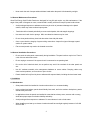
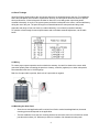
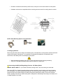
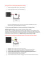
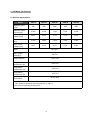
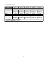
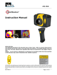
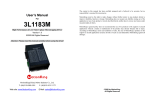
GENERAL INSTALLATION & USER MANUAL
GANZ ECO-ENERGY SOLAR PANELS
MODELS: GSP-06, GSP-12, GSP-30, GSP-40 & GSP-55
Read this manual completely before installing or using Ganz Eco-Energy Semi-Flexible Solar Panels.
1. Introduction
1-1 General Introduction
Thank you for choosing Ganz Eco-Energy Semi-Flexible Solar Panels. With proper operation and
maintenance, your GSP Solar Panels will provide you with clean renewable solar electricity for many years.
This Manual contains installation and safety information you need to be familiar with.
1-2 Disclaimer of Liability
This Manual does not constitute a warranty, expressed or implied. GANZ ECO-ENERGY does not assume
responsibility and expressly disclaims liability for loss, damage, or expense arising out of or in any way
connected with installation, operation, use or maintenance of solar panels. GANZ ECO-ENERGY reserves
the right to make changes to the product, specifications or Installation Manual without prior notice.
1-3 Warranty Information
The guarantee of this product is two years from purchase. The full warranty statement is available at our
website www.cbcamerica.com/ecoenergy/
1-4 Returning Ganz Products
Before returning, please contact the Distributor where originally purchased to obtain a Return Authorization
number (RA#). GANZ ECO-ENERGY will not accept any returns without a prior RA #.
2. Warnings
2-1 General Warnings
•
Install or use GSP solar panels for their intended purpose only.
•
Solar Panel interconnects generate Direct Current (DC) and are sources of power when they are
exposed to sunlight.
•
Physical Contact with the electrically active output terminals can result in burns, sparks, and electric
shock whether the panel is connected or disconnected.
•
DC power can arc across gaps and may cause injury or death if improper connection or
disconnection is made, or if contact is made with panel components that are damaged. Do not
connect or disconnect panels when the panels are exposed to sunlight or an external power source is
present.
•
Although GSP solar panels are durable, light in weight and semi flexible, we do not recommend
putting the solar panel in a high traffic area where walking on them will be consistent.
1
•
To avoid electric shock, fire, and injury, do not touch terminals while a panel is exposed to. Provide
suitable guards to prevent direct contact with the solar panel output terminals. (Such as insulated
tools and gloves).
•
To avoid electric shock, fire, and injury, Avoid dropping or allowing objects to fall on panels.
•
To avoid electric shock, fire, and injury, children should not be allowed near the installation of solar
panels.
•
To avoid electric shock, fire, and injury, do not puncture or damage the back or front sheet of a panel.
•
To avoid electric shock, fire, and injury, do not disassemble the panel, or remove any part installed by
the manufacturer.
•
To avoid electric shock, fire, and injury, do not use or install broken panels.
•
Do not expose solar panels to mirrors, lenses or other forms of sunlight concentration or light
enhancement.
•
Under normal conditions, a solar panel is likely to experience conditions that produce more current
and/or voltage than reported at standard test conditions. Accordingly, the values of Isc and Voc
marked on this panel should be multiplied by a factor of 1.25 when determining component voltage
ratings, conductor current ratings, fuse sizes, and size of controls connected to the solar output.
•
Although solar panels will produce some electricity in the shade, it is always best to install panels
where there is less shade and more exposure to direct sunlight.
3. General Precautions
3-1 General Safety Precautions
•
Turn off inverters and circuit breakers immediately, when a problem occurs.
•
Cover all panels in the panel array with an opaque cloth or material before making or breaking
electrical connections.
•
To avoid electric shock, fire, and injury, do not install the panel where flammable gases or vapors are
present. As sparks may occur.
3-2 General Handling Precautions
•
Reduce the chance of accidental exposure to live circuits by removing all metallic jewelry when
handling or installing panels.
•
Use insulated tools to reduce your risk of electric shock.
•
Do not pull the output cable. The output cable connection may become loose and cause a short
circuit, open circuit or shock.
•
Do not scratch or hit the back sheet or front sheet to avoid damage.
•
Do not strongly rub the plastic surface of the panel because there is a possibility of the plastic film
getting torn therefore causing an electric shock or short circuit.
2
•
Never touch the end of output cables with bare hands when the panel is illuminated by sunlight.
3-3 General Maintenance Precautions
Ganz Eco-Energy Semi-Flexible Panels are designed for long life and require very little maintenance. If the
angle of the panel is 5 degrees or more, normal rainfall is usually sufficient to keep the panel surface clean.
•
Avoid prolonged exposure to saltwater as this may be a risk of permanent damage to the plastic
surface, which may cause reduced output power.
•
Panels should be cleaned periodically to remove salt deposits, dirt and seagull droppings.
•
Use water and a soft cloth or sponge. Mild, non-abrasive cleaners may be used.
•
Do not clean panels with any chemicals but rather clean with plain water.
•
Once a year check the integrity of system wiring connections. Inspect for signs of damage to panel
surface or system cables.
•
Flat mounted panels may need to be cleaned more often.
3-4 General Installation Precautions
•
Do not touch the solar panel unnecessarily during installation. The panel surface may be hot. There is
a risk of burns and electric shock.
•
Do not unplug a connector if the system circuit is connected to an operating load.
•
Due to the risk of electrical shock, do not perform any work if the terminals of the solar panels are
wet.
•
Use UV resistant materials, wire management hardware to secure cables. Drooping cables may
cause various problems, such as short or open circuits.
•
Panels should be firmly fixed in place to withstand all expected loads, including wind and snow loads.
4. Installation
4-1 Site Selection
•
Solar panels should be installed in a location where there is no constant shading.
•
In the northern hemisphere, panels should ideally face south, and in the southern hemisphere, panels
should ideally face north.
•
In applications when the panels are installed in areas that have heavy snow, extreme cold or strong
winds take proper steps to maintain reliability and safety.
•
Avoid prolonged direct exposure to saltwater. Do not submerse in salt or fresh water.
•
When installing on a boat try to choose a location that will have sunlight regularly between 10:00 AM
and 3:00 PM.
3
4-2 Panel Tilt Angle
Ganz Eco-Energy panels produce the most power when they are pointed directly at the sun. For installations
where the solar panels are mounted to a permanent structure, the solar panels should be tilted for optimum
winter performance. A tilted solar panel will allow for about 50% more daily power output than panels
mounted horizontally. As a rule, if the system power production is adequate in the winter, it will be satisfactory
during the rest of the year. The panel tilt angle is measured between the solar panels and the ground.
Adjust the solar array to face true South (in northern latitudes), or true North (in southern latitudes).
To optimize a fixed tilt angle for annual performance and to eliminate seasonal adjustment, use the table
below:
4-3 Wiring
To ensure proper system operation and to maintain the warranty, be careful to observe the correct cable
connection polarity when connecting the panels to a battery, controller (regulator) or to other solar panels.
Recommended cable size is 16 AWG gauge.
Red wire of output cable is positive, black wire of output cable is negative.
4-4 Mounting the Solar Panel
•
Since the use and applications will be varied, from fixed to motion based applications, the actual
mounting process will depend on the application.
•
The best method is to use the four mounting holes to be secured to some form of bracket or raised
just above the surface (1/4” Minimum) to allow for circulation of air beneath the solar panel.
4
•
Be aware of obstructions and heavy traffic areas, as they are not the best location for solar panels.
•
Hardware used must be compatible with the mounting structure material to avoid galvanic corrosion.
NOTE: Other Mounting Options (sold separately)
4-5 Charging Batteries
When using the solar panel to charge 12V batteries (pairs of 6V batteries in series) please read the instruction
manual of the battery manufacturer. It is important to understand the application, characteristics and
instructions of the battery before connecting the solar panel.
•
•
Misunderstanding the battery may cause a serious accident by short circuiting the battery.
Only use 12 Volt Nominal battery banks that are rated to be “Deep Cycle”.
4-6 Connecting the GSP (Self Regulating) Panels to 12V Battery Banks
MODEL: GSP-6 & GSP-12 – (kit includes terminals, blocking diode, fuse, fuse holder) pre-connected.
Due to the GSP-6 & 12 panels low peak voltage a charge controller is not necessary to prevent the battery
from discharging. The factory installed diode placed in line with the positive output from the solar panel will
prevent reverse current back feeding from battery through the solar panel at night. The use of a blocking
diode is typically done when a smaller sized panel is designed for maintaining a float charge to a battery, and
a voltage regulator is not used.
5
Wiring Instructions: Self Regulating GSP Panels to Battery.
1. Connect the ring terminal of black (-) wire to battery (-)
2. Connect ring terminal of red (+) wire to the battery (+)
The factory installed diode and fuse can be removed for advanced installations and users.
Removing these components will not void the warranty.
4-7 Connecting the GSP (Regulation is Recommended) Panels to 12V Battery Banks
MODEL: GSP-30, 40 & 55 solar panel connection using Ganz Charge Controller
Due to the GSP-30, 40 & 55W panels high peak voltage a charge controller is recommended to prevent
the battery from discharging through the solar array at night and overcharging of the battery during the day.
Panels utilizing charge controllers do not require blocking diodes. The recommended charge controller for a
single GSP-30, 40 & 55W solar panel is The GANZ 4.5A charge controller (GCC-4.5A Kit).
Wiring Instructions: GSP Panels to GANZ 4.5A charge controller (GCC-4.5A Kit) to Battery.
1.
2.
3.
4.
5.
6.
7.
8.
Ganz 4.5A charge controller can be mounted in any position.
Ganz 4.5A can be mounted outdoors. Do not expose to ambi-ent temperatures above 60˚C.
It is best to mount to a vertical surface and allow space for air flow through the controller.
Connect the charge controller black wire (-) to the black 2 ft. battery cable using the blue wire nut.
Connect the charge controller red wire (+) to the red 2 ft. battery cable using the blue wire nut.
Connect the ring terminal of black battery (-) wire to the battery.
Connect ring terminal of red battery (+) wire to the battery.
Connect the black wire from the controller to the black (-) wire of the solar panel using the blue wire nut.
6
9. Connect the yellow wire from the controller to the red (+) of the solar panel using the blue wire nut.
10. Be very careful not to short circuit the solar array, or the controller will be damaged.
11. Make sure that controller is mounted in a way that water will drain from inside the case.
NOTE: Marine grade splice (supplied by user) may be substituted for the blue wire nuts included.
4-8 Connecting Multiple Batteries
This section is added as a courtesy for advanced users. Multiple Battery systems are all unique and can
be complicated. It is highly recommended that you seek out expert design assistance if you do not fully
understand Multiple Battery systems.
Multiple Batteries Installations:
2 x 12V batteries
in parallel
2 x 6V batteries
in series
Connecting Batteries - Series: When batteries are connected in series the voltage is cumulative while the
same capacity rating (amp hours) is maintained.
Connecting Batteries - Parallel: When batteries are in parallel the capacity (amp hours) of the battery is
cumulative while the voltage of the individual batteries is maintained. Batteries should be same rating and
same type of battery, i.e. flooded, gel or AGM.
4-9 Connecting Multiple GSP Solar Panels
This section is added as a courtesy for advanced users. Multiple Solar Panel systems are all unique and
can be complicated. It is highly recommended that you seek out expert design assistance if you do not fully
understand Multiple Solar Panel systems.
Connecting GSP Solar Panels - Parallel: When connected in parallel the charging current (amps) of the
panels are cumulative while the voltages of the panels remain the same (if there is no shading). For example,
two 12-volt, 3-amp panels wired in parallel would create a 12-volt, 6-amp system.
•
Solar Panels should be same rating and same type.
•
When using a single controller to regulate multiple panels be sure to select the suitable charge
controller to cover the total short circuit amps generated by all the panels added together.
•
It is recommended (and a better design) to use a dedicated GANZ 4.5A charge controller (GCC-4.5A
Kit) to each solar panel in a multiple parallel configuration. This allows each solar panel to charge
independently and not have any effect on the other panels, even if one or more panels are shaded.
•
To wire two devices in parallel, you connect the positive terminal of one to the positive terminal of
another, as well as the negative terminal of one to the negative terminal of another. In parallel wiring
7
voltage is constant while current is additive.
Connecting GSP Solar Panels - Series:
With series wiring, where the terminals are connected positive to negative, the voltage is added together,
while the amperage remains the same. For example, two 12-volt, 3-amp solar panels wired in series would
create a 24-volt, 3-amp system.
•
Solar Panels should be same rating and same type.
•
To wire two panels in series, you connect the positive terminal of one to the negative terminal of
another. In series wiring voltage is additive while current is constant.
•
A Bypass diode is recommended to prevent shading. If one panel is shaded, the current produced
by the un-shaded panel can flow through a bypass diode to avoid the high resistance of the shaded
panel. Bypass diodes will not be of use unless panels are connected in series to produce a higher
voltage.
4-10 Grounding the GSP Solar Panels and Controllers
Installations in Boats:
WARNING: Only ground the DC system to battery negative (one-point ground). Never ground the DC system
to the boat bonding system or to any metallic part, fixture, or component on the boat.
Installations in RV’s & Caravans:
Ground the solar panel(s) to the vehicle chassis with black wire. Multiple 12V nominal solar panels may be
wired together in parallel and grounded with one wire. Use red wire for the solar positive connection to the
controller or the battery.
Installations in Homes, Cabins & Other Land Based Systems:
NOTE: Earth grounding is recommended but not required. Grounding helps protect against lightning by
providing a direct path to earth. In areas prone to frequent lightning strikes, external lightning arrestors and/or
other means of protection may be needed.
8
5. GSP Model Specifications
5-1 Electrical Specifications
Model
GSP-6
GSP-12
GSP-30
GSP-40
GSP-55
Maximum power
[Pm]
6W
12W
30W
40W
55W
Maximum output
current [Imp]
0.39A
0.78A
1.74A
2.30A
3.20A
Maximum output
voltage [Vmp]
15.3V
15.3V
17.2V
17.2V
17.2V
Short-circuit current
[Isc]
0.42A
0.86A
1.93A
2.52A
3.56A
Open Circuit
Voltage [Voc]
19.2V
19.3V
21.6V
21.6V
21.6V
NOCT
45℃±2℃
Max. System
voltage [V]
120V DC
Power tolerance
+10% / -5%
Temperature
Coefficient of Isc
+ 0.05 %/℃
Temperature
Coefficient of Voc
- 0.35 %/℃
Temperature
Coefficient of Pm
- 0.45 %/℃
Operating
Temperature
-40℃ to 85℃
* Specifications are obtained under the standard test conditions of STC.
(STC: Irradiance 1000 W/m2, Panel temperature 25 ℃, AM 1.5)
* NOCT: Normal Operating Cell Temperature
9
5-2 Physical Specifications
Model
GSP-6
Type of Cells
Number of cells
Dimension
(H×W×D mm)
Weight
Material of Cable
Length of Cable
GSP-12
GSP-30
GSP-40
GSP-55
Polycrystalline silicon solar cell
32 (4×8)
32 (4×8)
36 (6×6)
72 (4×18)
72 (6×12)
300×252×14.5
400×358×14.5
560×521×14.5
760×458×14.5
880×520×14.5
0.64 Kg
1.06 Kg
1.98 Kg
2.30 Kg
3.31 Kg
PVC shielded cable with UV resistance
3m (2×1mm2)
Distance between
250×204 mm
350×310 mm
Grommets (H×W)
* The tolerance of dimensions is within ±1mm.
* Operating Temperature: -40 ℃ ~ +85 ℃
10
3m (2×1.5mm2)
510×473 mm
710×410 mm
830×472 mm