1
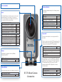
Lens Cover (Included)
Mounting and Lighting
Utilize industry standard mounting for the following mount and
lighting options:
Lenses
Mounting
Tripod Adaptor
Pan and Tilt Mount
Light Bracket for 177x Smart Cameras
Lighting for Monochrome Cameras
Advanced Illumination RL127, Red Ring Light
Lighting for Color Cameras
Advanced Illumination RL127, White Ring Light
The NI High-Performance Smart Cameras have a C lens mount.
National Instruments offers a number of C mount lenses.
These lenses include both low and high resolution options to
accommodate the different camera models.
NI 1772, 1772C, NI 1774, NI 1774C
Computar M0814-MP, 8mm, F1.4, Megapixel
Computar M1214-MP, 12mm, F1.4, Megapixel
Computar M1614-MP, 16mm, F1.4, Megapixel
Computar M2514-MP, 25mm, F1.4, Megapixel
Computar M3514-MP, 35mm, F1.4, Megapixel
NI 1776, NI 1776C, NI 1778
Computar M1620-MPV, 16mm, F2.0,2/3 inch, 3MP
Computar M2518-MPV, 25mm,F1.8, 2/3 inch, 3MP
Computar M3520-MPV, 35mm, F2.0,2/3 inch, 3MP
Fujinon HF12.5SA-1, 12.5mm, F1.4, 5 MP
Fujinon HF16SA-1, 16mm, F1.4, 5 MP
Fujinon HF25A-1, 25mm, F1.4, 5 MP
780024-01
780025-01
780026-01
780027-01
780033-01
The first is to use the starter kit for NI 177x Smart Cameras. The
starter kit includes all accessories listed in the table, and is the
easiest way to start using the NI 177x Smart Camera.
Starter Kit for NI 177x Smart Cameras
Power & I/O Accessory
Power Supply
M12 to DSUB cable for Power & I/O Accessory
M12 to RJ45 cable
M12 to VGA/USB cable
782043-01
The second option is to use the following M12 to Pigtail cable.
This cable provides a way to connect the smart camera power
and I/O lines to custom termination. The Power Supply for NI
Mount
177x Smart Cameras can also be connected to custom
termination utilizing the M12 to Pigtail cable to connect to
the Smart Camera.
153130-05
USB and VGA Video
View inspection images and connect additional storage via USB.
153064-01
782027-01
There are two main options for connecting power and I/O to
the camera.
Utilize Ethernet for enterprise connectivity, Modbus,
EtherNet/IP, and TCP/IP.
M12 VGA and USB Connector
M12 to VGA/USB Splitter Cable (1m)
782026-01
Power and I/O
782023-01
782024-01
782025-01
782525-01
782424-01
782423-01
Ethernet
M12 Ethernet Connector
M12 to RJ45 Cable (5m)
199173-01
748182-02
782570-01
NI 177x Smart Camera
Accessories
Cable
M12 to Pigtail cable (3m)
Power Supply
Power Supply for NI 177x Smart Cameras
153131-03
782032-01
1
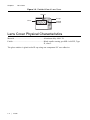
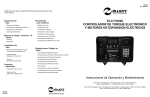
Lens Cover
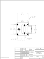
The lens cover protects the smart camera lens from dust and damage and is rated for IP67. The
lens cover keeps the aperture and focus settings from being changed. The following figures show
the dimensions of the lens cover included with the NI 177x Smart Camera.
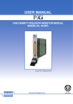
Figure 1-1. Lens Cover Dimensional Drawing
A
A
(45)
Ø1.772
(58.25)
Ø2.293
(51)
Ø2.008
(50)
Ø1.969
(46.70)
1.839
B
(53.25)
Ø2.096
© National Instruments
|
1-1
Chapter 1
Lens Cover
Figure 1-2. Detailed View of Lens Cover
Groove
IP Cap
Glass
Inclined
Feature
Lens Cover Physical Characteristics
Material .............................................................Aluminum alloy 6061-T6
Finish ................................................................Black anodic coating, per MIL-A-8625F, Type
II, class 2
The glass window is glued to the IP cap using one component UV cure adhesive.
1-2
| ni.com
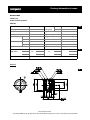
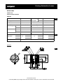
2
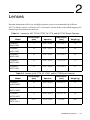
Lenses
National Instruments offers low and high resolution lenses to accommodate the different
NI 177x Smart Cameras. All lenses are 2/3 inch and C mount. Refer to the following pages for
detailed specifications about each lens.
Table 2-1. Lenses for NI 1772, NI 1772C, NI 1774, and NI 1774C Smart Cameras
Focal Length
(mm)
Aperture
Dimensions
(mm)
Weight (g)
Computar
M0814-MP
8
F1.4—F16C
33.5 x 28.2
70
Computar
M1214-MP
12
F1.4—F16C
33.5 x 28.2
65
Computar
M1614-MP
16
F1.4—F16C
33.5 x 28.2
65
Computar
M2514-MP
25
F1.4—F16C
33.5 x 36
75
Computar
M3514-MP
35
F1.4—F16C
33.5 x 38.2
87
Model
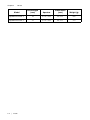
Table 2-2. Lenses for NI 1776, NI 1776C, and NI 1778 Smart Cameras
Focal Length
(mm)
Aperture
Dimensions
(mm)
Weight (g)
Computar
M1620-MPV
16
F2.0—F16.0
29 x 33.53
53
Computar
M2518-MPV
25
F1.8—F16.0
29 x 36.7
60
Computar
M3520-MPV
35
F2.0—F22.0
29 x 37.34
59
Fujinon
HF12.5SA-1
12.5
F1.4—F22
83 x 62
295
Model
© National Instruments
|
2-1
Chapter 2
Lenses
Model
Focal Length
(mm)
Aperture
Dimensions
(mm)
Weight (g)
Fujinon HF16SA-1
16
F1.4—F22
69 x 51
285
Fujinon HF25SA-1
25
F1.4—F22
44 x 33
315
2-2
| ni.com
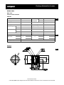
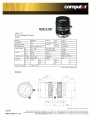
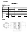
Factory Automation Lenses
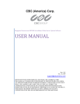
M0814-MP
8mm F1.4
for 2/3" format cameras
C-Mount
Model No.
M0814-MP
Effective
Front
f 21.5mm
Focal Length
8mm
Lens Aperture
Rear
f 12.0mm
Max. Aperture Ratio
1 : 1.4
Distortion
-1.1%(y=4.0)
Max. Image Format
8.8 x 6.6mm (f11mm)
Back Focal Length
13.1mm
Iris
F1.4 - 16C
Flange Back Length
17.526mm
Focus
0.3m - Inf.
Mount
C-Mount
Iris
Manual
Filter Size
M30.5 P=0.5mm
Focus
Manual
Dimensions
f33.5 x 28.2mm
32.1 x 24.1cm
Weight
Operation Range
Control
Object Dimension at M.O.D.
D
Angle of View
H
V
Operating Temperature
70g
67.1°
2/3"
56.3°
43.7°
2/3
51.9°
1/2"
C
42.5°
32.4°
-20°C ~ +50°C
M.O.D. : Minimum Object Distance
Dimensions
F
www.cbcamerica.com/cctv
© 2001 CBC (AMERICA) Corp. All rights reserved. NY Office: 55 Mall Dr. Commack, NY 11725 Tel: 1-800-422-6707 Fax: 631-543-5426
Factory Automation Lenses
M1214-MP
12mm F1.4
for 2/3" format cameras
C-Mount
Model No.
M1214-MP
Effective
Front
f 21.0mm
Focal Length
12mm
Lens Aperture
Rear
f 13.0mm
Max. Aperture Ratio
1 : 1.4
Distortion
-0.35%(y=4.0)
Max. Image Format
8.8 x 6.6mm (f11mm)
Back Focal Length
13.1mm
Iris
F1.4 - 16C
Flange Back Length
17.526mm
Focus
0.3m - Inf.
Mount
C-Mount
Iris
Manual
Filter Size
M30.5 P=0.5mm
Focus
Manual
Dimensions
f33.5 x 28.2mm
22.1 x 16.5cm
Weight
Operation Range
Control
Object Dimension at M.O.D.
D
Angle of View
H
V
Operating Temperature
65g
49.2°
2/3"
40.4°
30.8°
2/3
37.0°
1/2"
C
30.0°
22.7°
-20°C ~ +50°C
M.O.D. : Minimum Object Distance
Dimensions
F
www.cbcamerica.com/cctv
© 2001 CBC (AMERICA) Corp. All rights reserved. NY Office: 55 Mall Dr. Commack, NY 11725 Tel: 1-800-422-6707 Fax: 631-543-5426
Factory Automation Lenses
M1614-MP
16mm F1.4
for 2/3" format cameras
C-Mount
Model No.
M1614-MP
Effective
Front
f 18.5mm
Focal Length
16mm
Lens Aperture
Rear
f 13.2mm
Max. Aperture Ratio
1 : 1.4
Distortion
-0.3%(y=4.0)
Max. Image Format
8.8 x 6.6mm (f11mm)
Back Focal Length
13.1mm
Iris
F1.4 - 16C
Flange Back Length
17.526mm
Focus
0.3m - Inf.
Mount
C-Mount
Iris
Manual
Filter Size
M30.5 P=0.5mm
Focus
Manual
Dimensions
f33.5 x 28.2mm
16.5 x 12.4cm
Weight
Operation Range
Control
Object Dimension at M.O.D.
D
Angle of View
H
V
Operating Temperature
65g
38.0°
2/3"
30.8°
23.4°
2/3
28.2°
1/2"
C
22.7°
17.1°
-20°C ~ +50°C
M.O.D. : Minimum Object Distance
Dimensions
F
www.cbcamerica.com/cctv
© 2001 CBC (AMERICA) Corp. All rights reserved. NY Office: 55 Mall Dr. Commack, NY 11725 Tel: 1-800-422-6707 Fax: 631-543-5426
Factory Automation Lenses
M2514-MP
25mm F1.4
for 2/3" format cameras
C-Mount
Model No.
M2514-MP
Effective
Front
f 17.8mm
Focal Length
25mm
Lens Aperture
Rear
f 12.0mm
Max. Aperture Ratio
1 : 1.4
Distortion
-0.1%(y=4.0)
Max. Image Format
8.8 x 6.6mm (f11mm)
Back Focal Length
13.1mm
Iris
F1.4 - 16C
Flange Back Length
17.526mm
Focus
0.3m - Inf.
Mount
C-Mount
Iris
Manual
Filter Size
M30.5 P=0.5mm
Focus
Manual
Dimensions
f33.5 x 36.0mm
10.6 x 8.0cm
Weight
Operation Range
Control
Object Dimension at M.O.D.
D
Angle of View
H
V
Operating Temperature
75g
24.9°
2/3"
20.0°
15.1°
2/3
18.2°
1/2"
C
14.6°
11.0°
-20°C ~ +50°C
M.O.D. : Minimum Object Distance
Dimensions
F
www.cbcamerica.com/cctv
© 2001 CBC (AMERICA) Corp. All rights reserved. NY Office: 55 Mall Dr. Commack, NY 11725 Tel: 1-800-422-6707 Fax: 631-543-5426
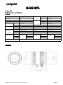
M1620-MPV
f=16mm F2.0
for 2/3 type Cameras, 3 Megapixel
C‐Mount
Model No.
M1620-MPV
Effective
Front
φ18.0mm
Focal Length
16mm
Lens Aperture
Rear
φ11.0mm
Max. Aperture Ratio
1:2.0
Distortion
2/3 type
Max. Image Format
8.8mm x 6.6mm(φ11mm)
1/1.8 type
-0.06%(y=4.32)
Iris
F2.0 ‐ F16.0
1/2 type
-0.07%(y=4.0)
Focus
0.2m ‐ Inf.
Back Focal Length
14.7mm
Iris
Manual
Flange Back Length
17.526mm
Focus
Manual
Mount
C-Mount
8.8cm x 11.74cm
Filter Size
M27.0 P=0.5mm
6.93cm x 9.20cm
Dimensions
φ29mm x 33.53mm
6.40cm x 8.53cm
Weight
53.0g
Operation Range
Control
2/3 Type
Object Dimension
1/1.8 Type
at M.O.D.
1/2 Type
Angle of View
D
2/3 Type
37.7°
1/1.8 Type
30.1°
0.09%(y=5.5)
1/2 Type
28.0°
H
30.7°
24.3°
22.6°
V
23.3°
18.5°
17.1°
Operating Temperature
-10℃ ‐ +50℃
M.O.D. : Minimum Object Distance
Dimensions
Specification is subject to change without any notice.
2009.06
M2518-MPV
f=25mm F1.8
for 2/3 type Cameras, 3 Megapixel
C‐Mount
Model No.
M2518-MPV
Effective
Front
φ18.0mm
Focal Length
25mm
Lens Aperture
Rear
φ13.0mm
Max. Aperture Ratio
1:1.8
Distortion
2/3 type
Max. Image Format
8.8mm x 6.6mm(φ11mm)
1/1.8 type
-0.02%(y=4.32)
Iris
F1.8 ‐ F16.0
1/2 type
-0.02%(y=4.0)
Focus
0.2m ‐ Inf.
Back Focal Length
13.8mm
Iris
Manual
Flange Back Length
17.526mm
Focus
Manual
Mount
C-Mount
5.48cm x 7.31cm
Filter Size
M27.0 P=0.5mm
4.32cm x 5.73cm
Dimensions
φ29mm x 36.37mm
3.98cm x 5.31cm
Weight
60.0g
Operation Range
Control
2/3 Type
Object Dimension
1/1.8 Type
at M.O.D.
1/2 Type
Angle of View
D
2/3 Type
24.6°
1/1.8 Type
19.5°
0.03%(y=5.5)
1/2 Type
18.1°
H
19.9°
15.7°
14.5°
V
15.0°
11.8°
10.9°
Operating Temperature
-10℃ ‐ +50℃
M.O.D. : Minimum Object Distance
Dimensions
Specification is subject to change without any notice.
2009.06
M3520-MPV
f=35mm F2.0
for 2/3 type Cameras, 3 Megapixel
C‐Mount
Model No.
M3520-MPV
Effective
Front
φ18.0mm
Focal Length
35mm
Lens Aperture
Rear
φ12.0mm
Max. Aperture Ratio
1:2.0
Distortion
2/3 type
0.011%(y=5.5)
Max. Image Format
8.8mm x 6.6mm(φ11mm)
1/1.8 type
0.010%(y=4.32)
Iris
F2.0 ‐ F22.0
1/2 type
0.009%(y=4.0)
Focus
0.2m ‐ Inf.
Back Focal Length
18.0mm
Iris
Manual
Flange Back Length
17.526mm
Focus
Manual
Mount
C-Mount
3.48cm x 4.63cm
Filter Size
M27.0 P=0.5mm
2.74cm x 3.63cm
Dimensions
φ29mm x 37.34mm
2.53cm x 3.37cm
Weight
59.0g
Operation Range
Control
2/3 Type
Object Dimension
1/1.8 Type
at M.O.D.
1/2 Type
Angle of View
D
2/3 type
17.8°
1/1.8 tyoe
14.0°
1/2 type
13.0°
H
14.3°
11.2°
10.4°
V
10.7°
8.5°
7.8°
Operating Temperature
-10℃ ‐ +50℃
M.O.D. : Minimum Object Distance
Dimensions
Specification is subject to change without any notice.
2009.06
#$
(. #$
&0#"*! '
(. ɑɓɉɐ
ɒɋɉɐ
ɍɓɉɌ
ԥɐɋ
ɏ
ɏ
ԥɐɋ
ɐɉɑ
ɐɉɑ
ԥɐɌ
ɓ
ɓ
ԥɐɌ
ɌɌ
ɩɠ ɜ ɭ
ɌɌ
ɩɠɜ ɭ
ɍɓɉɌ
ɍɍ Ɍɑ
ɍɍ Ɍɑ
ɍ
ɡɜɭ
ɋ
ɋ
Ɍɉɏ
Ɍɉɏ
ɰʉʄʏȻɕȻʈʈ
(. #$
&#%*$$
ɏɓɉɐ̈́ɼʏ͡ͅȻ
ɍɓɉɌ
ɓ
ɩɠɜ ɭ
ɌɌ
ɌɌ
ɩɠ ɜ ɭ
ɍɓɉɌ
'(* &%
ɍɍ Ɍɑ
ɍɍ Ɍɑ
#. '*/).
"
"
,0&(#."-1"* 5,))
#
#
#
#
#
#
&+)
( )
%$&%$
%$&%$
%$&%$
%$&%
$
ɍɉɓ
ɍɉɓ
Ɍɉɏ
ɋ
ɋ
Ɍɉɏ
%# ,
.
ɍ
ɡɜɭ
ɍ
ɡɜɭ
#$
ԥɐɋ
ɏ
ԥɐɋ
ɏ
ԥɐɌ
ɐɉɑ
ɐɉɑ
ԥɐɌ
ɓ
ɰʉʄʏȻɕȻʈʈ
( )%
ɏ
ɏ
ɰʉʄʏȻɕȻʈʈ
(. #$
%$&%$
%$&%$
%$&%$
%$&
%$
%$&%$
%$&%$
'#
%$&%$
%$&%$
%$&%$
%$&%$
%$&%$
%$&%$
%$&%$
%$&%$
'#
'#
'#
'#
&
&
&
&
'#
ɍɓɉɌ
ԥɐɌ
ɏ
ɐɉɑ
ԥɐɋ
ɓ
ɐɉɑ
ԥɐɋ
ɌɌ
ɓ
&
&
&
&
&
&
&
&
&
&
&
&
"&# )*% % ($$
- *+' #&) * &%
(&$$#%$$
&
&
&
&
&
&
&
))
$(")
ɍɉɓ
Ɍɉɓ
ɋ
ɋ
Ɍɉɓ
ɏ
ɏ
ɰʉʄʏȻɕȻʈʈ
ɰʉʄʏȻɕȻʈʈ
3
#*(($$
&+%*
ɏ
ɡɜɭ
ɍɉɓ
ɡɜɭ
&
Ɍɑ
ɌɌ
ɩɠɜ ɭ
ɍɍ
Ɍɑ
ɩɠ ɜ ɭ
ɒɑ̈́ɼʏ͡ͅ
ɍɍ
ԥɐɌ
&+) %%
(&$(&%*%)$
!* $%) &%)
*
.$$
(. ɐɐɉɐ̈́ɼʏ͡ͅ
ɍɓɉɌ
"
/&*$*"40"*/&+*01"(+*$".0%*))0%"3&((&* ."/"0+)
(. ɒɐɉɐ̈́ɼʏ͡ͅ
#"
*/).
"%2"."(&6"!%&$%."/+(10&+* +), 0*!
(&$%03"&$%0("*//1,,+.0&*$0+)"$,&4"(5
0%+.+1$%(5."!1 &*$"..0&+*//"!+*!"/&$*
0" %*+(+$5 1(0&20"!#.+).+! /0("*/"/
%" %.0/%+3*00%".&$%0 +),."/)"$,&4"(
/1,,+.0&*$("*/*!0%"+#*+.!&*.5
("*/
/0%"*1)".+#(&*"/&* ."/"/0%"!&/,.&05&*
" +)"/&$$".
ɍɉɓ
ɍ
ɡɜɭ
ɍɉɓ
&"#+#,./,# .#
!
/&*$*"40"*/&+*01"(+*$".0%*))0%"3&((&* ."/"0+)
ɏ
ɰʉʄʏȻɕȻʈʈ
#$
(.
"
*,#$ +&0#' (#,
&0%(+ '&*$'*+#+.&.&/*!#+1 /
ɏ
#$
)/ ',&-
"
!
"
#$ +&0#'/++*,.&)$#)-
*, !%&)#&-&*) &0#"*! '
# ./,#)"&! .&*)-
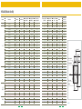
4
%)&()!0
!) /
(&+*%$
&#%*
'(*+(+##&'%
(&%*'(!%!'#'&!%*
(&$&+%*
"'(!%!'#'&!%*
(&$&+%*
!)*%*-%
* '!%!'#'&!%*)△
%*(%'+'!#'&)!*!&%
(&$&+%*
.!*'+'!#'&)!*!&%
(&$$'#%
"&#!)*%
!%!(
#*!,!##+$!%*!&%
!)*&(*!&%
'(*+(*+##&'%
$ ! **!&%#
※
※
※
21
22
$'#%
"'(!%!'#'&!%*
△
(%"
"&+)
(&%*'(!%!'#'&!%*
%*(%'+'!#
.!*'+'!#
※y=f・θ
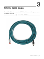
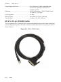
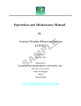
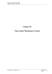
M12 to RJ45 Cable
3
Use the M12 to RJ45 cable to connect the NI 177x Smart Camera to the development computer.
The cable is 5 meters long.
Figure 3-1. M12 to RJ45 Cable
© National Instruments
|
3-1
Chapter 3
M12 to RJ45 Cable
M12 to Ethernet Cable Specifications
Mechanical Characteristics
Number of positions..........................................8
Shielded ............................................................Yes
Cable diameter ..................................................6.40 mm
Cable exit ..........................................................Straight
Cable structure ..................................................4x2xAWG26/7; S-FTP
Smallest bending radius,
fixed installation min. .......................................32 mm
Smallest bending radius,
movable installation min...................................32 mm (cable, flexible installation)
Ambient temperature (operation)......................-25 °C to 60 °C (cable, fixed installation)
-5 °C to 60 °C (cable, flexible installation)
Material Data
Inflammability class acc. to UL 94 ...................HB
Outer sheath, material .......................................PUR
External sheath, color .......................................water blue RAL 5021
Line Characteristics
Conductor cross section ....................................0.14 mm²
AWG signal line................................................26
Conductor structure signal line .........................7 x 0.16 mm
Core diameter including insulation...................1 mm
External cable diameter ....................................6.4 mm
Wire colors........................................................White-blue, white-orange, white-green,
white-brown
External sheath, color water blue......................RAL 5021
Insulation resistance5 G*km
Conductor resistance 150 m/m
Transmission characteristics (category)............CAT6A
Working capacitance.........................................42 pF
Wave impedance...............................................100 ± 5% (at 100 MHz)
Signal speed ......................................................0.72 c
Signal runtime...................................................46 ns/m
Shield attenuation .............................................60 dB (Up to 1000 MHz)
Interference suppression ...................................90 dB (Up to 1000 MHz)
3-2
|
ni.com
Nominal voltage, conductor ............................. 125 V
Test voltage, conductor..................................... 1000 V
Twisted pairs..................................................... 2 cores to the pair
Type of pair shielding....................................... Aluminum-lined polyester foil
Overall twist ..................................................... 2 cores with 2 fillers to the core
Shielding ........................................................... Tinned copper braided shield
Optical shield covering ..................................... 65%
Outer sheath, material....................................... PUR
Material conductor insulation ........................... Cell PE
Conductor material ........................................... Bare Cu litz wires
Cable weight ..................................................... 44 kg/km
Smallest bending radius,
fixed installation min. ....................................... 32 mm
Smallest bending radius,
movable installation min. ................................. 32 mm
© National Instruments
|
3-3
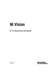
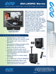
4
M12 VGA/USB Cable
Use the M12 VGA/USB cable to view inspection images via a VGA monitor, and to connect
addition storage via USB. Refer to the NI 177x Smart Camera User Manual for signal
assignments. The cable is 1 meter long.
Figure 4-1. M12 to VGA/USB Splitter Cable
© National Instruments
|
4-1
Chapter 4
M12 VGA/USB Cable
Figure 4-2. View of the VGA and USB Connectors
4-2
|
ni.com
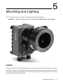
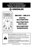
5
Mounting and Lighting
NI 177x Smart Cameras use industry-standard mounting and lighting.
Figure 5-1. Smart Camera with lens cover, light mounting bracket, and ring light
Lights
The lights for the NI 177x Smart Camera are manufactured by Advanced Illumination. Because
the lights are current-driven light heads, you can connect the lights to smart cameras with built-in
direct drive lighting controls. Refer to the following page for specifications for the RL 127 white
ring light and RL 127 red ring light.
© National Instruments
|
5-1
Chapter 5
Mounting and Lighting
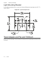
Light Mounting Bracket
Use the light mounting bracket to connect the Advanced Illumination ring lights to the NI 177x
Smart Camera.
Figure 5-2. Light Mounting Bracket
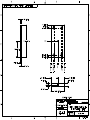
Tripod Adapter and Pan and Tilt Mount
Refer to the following pages for the mechanical drawings for the tripod adapter and the pan and
tilt mount.
5-2
| ni.com
RL127
High Brightness LED Ring Light
Intense illumination in a compact (4.6” diameter) housing
IP65 Compliant Design
Axial light source designed for inspecting non-specular objects
Ordering Information
Standard Product Variation:
Shipped Within Two Weeks
Standard Product:
Shipped Next Day
Optional Light
Conditioning
Spectral
wavelength
RL127-WHIIC
Optional power
compatibility
Configured with inline
Current Source
RL127
RL127-WHIC5
Configured for use with the
Pulsar 320
-
XXX
XX
(blue) 470
(red) 625
(white) WHI
IC
IS
C2
C3
C5
Alternative
Connector
X
XXX
P
M12*
(Diffuser)
(male)
D
(Polarizer)
IC = iCS (requires 24v power supply)
IS = iSU (requires 24v power supply)
C2 = Ai Connector
C5 = Pulsar 320 Connector
Available with IC and IS options only
Dimensional Information
The RL127 can be
mounted using brackets:
LB101, LB103, or LB105
(not included)
Cable Length: 1.5 Meter (59”)
Current Specifications
Standard Product Information
blue
@24
red
white
320 320 320
mA
Weight:
304 g (11 oz.)
Finish:
Black Anodized
Operating Temperature:
0-60 C
Meets Specifications:
CE, RoHS
Product Lifetime:
50,000 hours
a d v a n c e d i l l u m i n a t i o n .c o m
04.18.2011
0.550in
13.97mm
0.325in 8.26mm THRU
0.165in
4.19mm
30°
7.030in
178.57mm
0.470in
11.94mm
2.000in
50.81mm
0.880in
22.35mm
1.760in
44.70mm
UNLESS OTHERWISE SPECIFIED:
DIMENSIONS ARE IN INCHES
SURFACE FINISH:
TOLERANCES: .000= +/- 0.005"
.00= +/- 0.010"
LINEAR:
NAME
DRAWN
CHK'D
APPV'D
MFG
Q.A
SCHUBERT
FINISH:
BURNISHED
DEBUR AND BREAK SHARP EDGES
SIGNATURE
DATE
5/2/2012
Phone +1 (412) 487-8211
Fax
+1 (412) 486-3157
MATERIAL:
304 STAINLESS STEEL
NO.
CHANGE
DATE
INIT.
WEIGHT:
REVISION
TITLE:
NI Smart Camera
Pan and Tilt Mount
www.apgvision.com
NOTES:
Saved on Wednesday, May 02, 2012 2:21:19 PM
DO NOT SCALE DRAWING
Allison Park Group, Inc. (APG)
4055 Alpha Drive
Allison Park, PA 15101 USA
DWG NO.
SCALE:1:2
A3
748182-01
SHEET 1 OF 2
3.861in
98.08mm
0.171in 4.34mm THRU
8 HOLES
3.771in
95.78mm
1.970in
50.03mm
1.850in
46.99mm
1.550in
39.37mm
0.265in 6.73mm THRU
0.161in 4.09mm THRU
3 HOLES
2.375in
60.32mm
UNLESS OTHERWISE SPECIFIED:
DIMENSIONS ARE IN INCHES
SURFACE FINISH:
TOLERANCES: .000= +/- 0.005"
.00= +/- 0.010"
LINEAR:
NAME
DRAWN
CHK'D
APPV'D
MFG
Q.A
SCHUBERT
FINISH:
BURNISHED
DEBUR AND BREAK SHARP EDGES
SIGNATURE
DATE
5/2/2012
Phone +1 (412) 487-8211
Fax
+1 (412) 486-3157
NO.
CHANGE
DATE
INIT.
TITLE:
www.apgvision.com
MATERIAL:
304 STAINLESS STEEL
NOTES:
Saved on Wednesday, May 02, 2012 2:21:19 PM
DO NOT SCALE DRAWING
Allison Park Group, Inc. (APG)
4055 Alpha Drive
Allison Park, PA 15101 USA
WEIGHT:
DWG NO.
SCALE:1:2
REVISION
NI Smart Camera
Pan and Tilt Mount
A3
748182-01
SHEET 2 OF 2
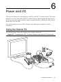
6
Power and I/O
There are two options for connecting power and I/O to the NI 177x Smart Camera. The easiest
method is to use the Starter Kit for NI 177x Smart Cameras, which includes the Power & I/O
Accessory, the power supply, and the 3 cables you need: the M12 to DSUB, the M12 to RJ45,
and the M12 to VGA/USB.
The second option is to use the M12 to Pigtail cable and the power supply for custom
termination.
Using the Starter Kit
The following figure shows the complete setup using the Starter Kit.
Figure 6-1. Connecting the NI 177x Smart Camera to the Power & I/O Accessory
© National Instruments
|
6-1
Chapter 6
Power and I/O
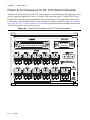
Power & I/O Accessory for NI 177x Smart Cameras
The Power & I/O Accessory for NI 177x Smart cameras is a terminal block that simplifies power
and I/O signal configuration. It uses a 25-pin D-SUB connector and a 17-pin M12 to 25-pin
D-SUB cable. Provides spring termination for accessing digital I/O, trigger lines, direct drive
LED output, 9-pin D-SUB for RS232, and 2-pin power connector. Refer to the Power and I/O
Accessory for NI 177x Smart Cameras User Guide for operation instructions and specifications.
The following figure shows the accessory.
Figure 6-2. Power & I/O Accessory for NI 177x Smart Cameras
RS-232
CAMERA
13
1
14
25
INPUTS
INP
IN0
IN1
IN2
IN3
24V IN
TRGIN
NATIONAL
INSTRUMENTS
OUT0
T0
OUT1
T1
OUT2
OUT3
LED DRV
RV
24V OUT
SAFE
AFE
MODE
6-2
|
ni.com
Power Supply for NI 177x Smart Cameras
Use the 24 V power supply to connect to the Power & I/O Accessory.
Figure 6-3. Power Supply
Power Supply Specifications
Length............................................................... 2 m
Input Requirements
Input Voltage Range ......................................... 100 (-10%) VAC to 240 (+10%) VAC
Input Frequency Range..................................... 47 Hz to 63 Hz
Input Power Consumption at no load ............... 0.3 W Max
Input In-rush Current ........................................ 50 A Max
Input Current..................................................... 0.8 A Max
Output Requirements
Output Voltage ................................................. +24 V
Output Regulation............................................. 22.8 V to 25.2 V
Output Load Range........................................... 0 to 1.25 A
© National Instruments
|
6-3
Chapter 6
Power and I/O
Output Ripple and Noise...................................240 mV Max at 20 Mhz bandwidth with
10 UF/50 V capacitance and 104/50 V
ceramic capacitor.
Efficiency83.62% at average of 25/50/75/100% loads
115 and 230 VAC input
Line Regulation.................................................2% Max
Hold Up Time ...................................................10 ms Min at 110 VAC full load
Turn On Time ...................................................2 s Max at 110 VAC full load
M12 to 25-pin DSUB Cable
The I/O connector is a 17-pin male M12 connector that provides power to the smart camera and
transmits digital I/O signals. This cable is included with the Power & I/O Accessory for NI 177x
Smart Cameras.
Figure 6-4. M12 to DSUB Cable
6-4
|
ni.com
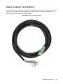
Using Custom Termination
You can use the power supply from above in conjunction with the M12 to Pigtail cable, which
enables you to connect the smart camera power and I/O lines to custom termination. The
following figure shows the M12 to Pigtail cable.
Figure 6-5. M12 to Pigtail Cable
© National Instruments
|
6-5
Chapter 6
Power and I/O
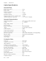
Cable Specifications
General Data
Rated current at 40°C........................................1.5 A
Rated voltage ....................................................30 V
Number of positions..........................................17
Volume resistance5 m
Insulation resistance10 M
Stripping length of the free conductor end .......35 mm
Ambient temperature (operation)......................-25 °C to 90 °C (female)
General Characteristics
Standards/regulations........................................M12 connector IEC 61076-2-101
Coding...............................................................A - standard
Surge voltage category......................................II
Pollution degree ................................................3
Degree of protection .........................................IP65/IP68/IP69K
Torque ...............................................................0.4 Nm (M12 connector)
Contact material ................................................CuZn
Contact surface material ...................................Ni/Au
Contact carrier material ....................................TPU GF
Material of grip body ........................................TPU, hardly inflammable, self-extinguishing
Material, knurls .................................................Zinc die-cast, nickel-plated
Sealing material ................................................NBR
Status display ....................................................No
Conductor Data
Cable type .........................................................PVC black
Conductor cross section ....................................0.14 mm²
AWG signal line................................................26
Conductor structure signal line .........................18x 0.10 mm
Core diameter including insulation...................1 mm ±0.05 mm
External cable diameter ....................................6.40 mm
Wire colors color-coded....................................DIN 47100
External sheath, color .......................................Black RAL 9005
Overall twist......................................................Wires twisted in layers
Outer sheath, material .......................................PVC
Material conductor insulation ...........................PVC
Conductor material ...........................................Bare Cu litz wires
6-6
|
ni.com
Smallest bending radius,
movable installation.......................................... 96 mm
Ambient temperature (operation) ..................... -5 °C to 80 °C (cable, flexible installation)
-25 °C to 80 °C (cable, fixed installation)
© National Instruments
|
6-7