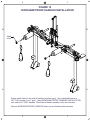
1
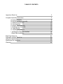
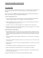
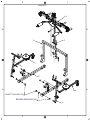
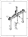
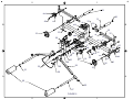
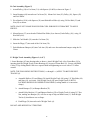
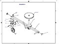
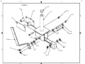
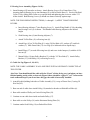
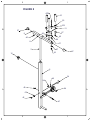
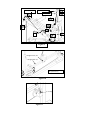
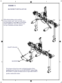
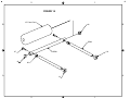
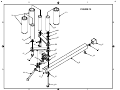
OWNERS MANUAL
UPPERTONE
Physical Therapy Equipment
Model No. UT 93A
GPK Inc., 535 Floyd Smith Dr., El Cajon, CA 92020, 800-468-8679, 619-593-7381, Fax: 619-593-7514, www.gpk.com
TABLE OF CONTENTS
Uppertone Parts List
3
Complete Assembly Instructions
A. Frame Assembly
B. Deltoid Lat Slider Assembly
C. Deltoid/Lat Assembly
D. Curl Assembly
E. Weight Track Assembly
F. Rowing Lever Assembly
G. Cable Set Up
H. Installing The Weights
I. Installing the Rickshaw Handles
J. Back Rest Installation
5
5
5
10
12
12
15
15
18
18
18
Back Rest Parts List
Adjustable Handles Parts List
Using the Uppertone
Maintaining the Uppertone
Warranty
21
23
25
25
25
UPPERTONE PARTS LIST
Part No.
1
2
3
4
5
6
7
8
9
10
11
12
13
14
15
16
17
18
19
20
21
22
23
24
25
26
27
28
29
30
30b
31
32
33
34
35
36
37
38
38b
39
40
41
42
43
44
44c
45
46
47
47b
Description
Main Frame
Frame Base
Frame Post
Weight Track
Rowing lever
Deltoid/Lat Slider
Rowing Adjuster
Rowing Arm (Right & Left side)
10-24 Nut
Black 4.25” Pegs.
Tri-Pin Plate
Wing Handle
Not Used
Pulley 3"
Not Used
Pulley 4 ½” - 3/8” bore
Pulley 4 1/21” - 3/4" bore
Weight Truck
Not Used
Shims (Truck)
Rubber Bumper
Bumper Plate with pulley bracket
Crank & Height Adjustment Screw
Washer 5/8” (Nylon)
Shaft Collar 13/16”
Swing Plate
Deltoid/Lat Arm
Deltoid/Lat Handle
T-Pin
Curl Arm
Curl Elbow Pivot Bracket
Curl Handle
Shaft Collar ¾”
Cable Assembly
Cable Bolt - with 3/8” nut
Caps – Square 1”
Plugs – Round 1”
Plugs - Square 1”
Plugs - Square 1 ¼”
Plug - Rectangular l”x2"
Plugs 1.5"
Mushroom Bumper
Hex Lock Nuts,1/4-20
Hex Lock Nuts 3/8-16
Not Used
Hex Bolts 1/4-20 X 2
Hex Bolts 1/4-20 X 1.5
Hex Bolts 3/8-16 X 1
Not Used
Hex Bolts 3/8-16 X 2
Truss Head 3/8-16 X 2.25
Comment
Qty
1
2
1
2
2
1
2
2
4
7
2
4
16
4
2
2
With eyebolt & locknut
4 if optional backrest is ordered
5 if optional QuadAdjustable handle is ordered
4
2
2
1
1
1
4
2
2
2
2
2
2
6
1
2
2
6
8
4
1
8
4
8
32
4
2
7
6
2
UPPERTONE PARTS LIST
Part No.
48
49
50
51
52
53
54
55
56
57
58
59
60
61
62
63
64
65
66
67
68
69
70
71
72
73
74
75
76
77
78
93
105
706
900
Description
Comment
Hex Bolts 3/8-16 X 2.75
Hex Bolts 3/8-16 X 3.25
4 if optional QuadAdjustable handle is ordered
Hex Bolts 3/8-16 X 3.75
Hex Bolts 3/8-16 X 4
2" Sq. Rubber Caps
White Nylon Spacer 1/4 X 1/2 X 1
Black Spacer 3/8 X 3/4 X 1/8
Not Used
Black Spacer 3/8 X 3/4 X 3/8
Black Spacer 3/8 X 3/4 X 1/2
Black Spacer 3/8 X 3/4 X 7/8
Black Spacer 1/4 X 3/4 X 1 ¼
Black Spacer 3/4 X 1 X 1/2
Black Spacer 3/4 X 1 X 3/16
Black Spacer 3/4 X 1.5 X .125
Bronze Bearing 3/4 X 1 X 5/8
Black Spacer 1 X 1 ½ X 1/8
Flanged Bronze Bearing 3/4 X 7/8 X 3/4
Flanged Bronze Bearing 3/8 X 5/8 X 3/4
Flat Steel Washer 3/8”
Weight - 10 pound plates
Black Foam Tube, 3.5” X 8”L
Black Foam Tube 1.5” X 6”L
Black Foam Pad 3” X 5”X 5”
Not Used
Black Foam Tube, 1.5” X 4"L
Spring Clips
Decals - CALIBRATION
Decals - UPPERTONE
Decals - GPK
Assembly Manual & Drawings
Lock Washers
7 if optional QuadAdjustable handle is ordered
Black Button Head 3/8 X 16 X 2.75
Truck Rubber Stop
Double Pulley Bracket
Qty
4
2
2
6
4
2
10
4
2
6
4
2
2
2
4
4
12
4
8
4
2
2
2
7
2
2
1
1
1
3
2
2
2
COMPLETE ASSEMBLY INSTRUCTIONS
TOOLS REQUIRED:
(1) 5/32” Allen wrench, (2) Adjustable open end wrench, (3) 7/16 open end, box end wrench (4) 9/16
open end, box end wrench, (5) 3/8 - 3/4", 3/8 drive socket set, (6) 3/8 drive ratchet wrench &
extension
Figure 1 shows how the UPPERTONE should look when it is fully assembled. Keep this figure in
front of you at all times to help you assemble the UPPERTONE.
A: Frame Assembly (Figures 1 & 2)
1. Lay Frame Base (part #2) pieces on the floor about 42" apart and with ROW STOPS pointing
outward. Fit the heavy Rubber caps (52) snugly over the ends of the frame base.
2. Lift the U Shaped Main Frame (1) onto the Frame Base (#2) as shown in Figure 2 with the 3/8”
(2.75” long) Hex Bolts (48) and the Nuts (42).
3. Attach the 3” Pulleys (14) as shown using the 3/8”(4” Long) Hex Bolts (51) and Nuts (42).
4. Bolt the Frame Post (3) onto the U Shaped Main Frame (1) as shown using the 3/8” (2.75” Long)
Black Button Head Bolts (105) and Nuts (42).
B: Deltoid/Lat Slider Assembly (Figure 3)
1. Slip the Deltoid/Lat Slider (6) over the Frame Post (3) as shown in Figure 3 and let it rest on the
bottom of the Frame Post (3). When you slip the Delt/Lat Slider (6) over the Frame Post (3) make
sure the shafts for the pulleys and spacers (e.g. part 60) face to the inside of machine as shown in
Figure 3.
2. Get the Crank Shaft (23) shown in Figure 4 and remove the 13/16” Shaft Collar (25) and Washer
(24) from it.
3. Insert the Crank Shaft (23) through the bottom tab as shown in Figure 3, but do not slide it all the
way up to the nut.
4. Slide the Washer (24) over the Crank Shaft (23) and then slide the 13/16” Shaft Collar (25) on top
of the washer.
5. Now thread the Crank Shaft (23) through the top nut, till it can not be turned any more.
6. Make sure the Washer (24) and the Shaft Collar (25) are resting at the very bottom.
7. Tighten the Shaft Collar (25) on the Crank Shaft (23) using the 5/32 “ Allen Wrench to screw in
the set screw in the shaft collar
Turning the crank should now raise and lower the entire Deltoid Slider assembly.
5
2
1
FIGURE 1
B
B
A
A
2
1
2
1
FIGURE 2
3
105
B
B
1
WEIGHT STOP
400
39
67
39
42
67
65
42
14
67
42
67
A
2
52
42
65
A
ROW STOP
48
56
65
65
900
56
2
67
67
51
1
2
1
FIGURE 3
6
B
B
3
1
2
A
4
SHAFT COLLARS (32)
BRONZE BEARINGS (65)
5
2
1
A
2
1
FIGURE 4
B
B
25
24
45
67
23
67
42
93
A
A
10
73
2
1
C: Deltoid/Lat Assembly (Figures 5)
1. Slide the bronze spacer (60) and then the 4 ½” pulley (17) over each of the ¾” shafts which are
located near the center and protruding horizontally from the Delt/Lat slider.
2. Install the Swing Plates (26). There are 4 identical Swing Plates (26), 2 will be mounted
horizontally, and 2 will be mounted vertically. Carefully follow the steps below:
a. Slide one Spacer (61) over each shaft and push up against each 4 1/2#' Pulley (I7). Slide
Spacer (62) over each shaft and Push up against Spacer (61).
b. Slide Bronze Bearing (63) over each shaft and push up against Spacer (62).
c. Attach one Pulley (14) to each Horizontal Swing Plate pair (26) with Spacer (54) between
Pulley and Plate using a 3/8” Hex Bolt (45b) and Nut (42).
d. Slide one Horizontal Swing Plate (26) over each Bronze bearing (63) and push up against
Spacer (62). Swing Plates will now pivot on Bearing (63). They should rest in position on
the stop.
e. Slide Spacer (64) over each shaft and push it up against Horizontal Swing Plate (26).
f. Attach one Pulley (14) to each Vertical Swing Plate pair (26) with Spacer (56) between
Pulley and Plates. Use 3/8 Hex Bolt (47) and Nut (42).
g. Slide one pair of Vertical Swing Plates (26) over each Spacer (63) and push up against the
Spacer (64). The Swing Plates should now pivot on Bearing (63) and should rest in
a vertical position against stop.
3. Insert Bearings (65) into tubes on Deltoid/Lat Arms (27). Slide Deltoid/Lat Arm (27) over each
shaft and push up against vertical Swing Plate (26). Insert T-pin (29) through lower hole of Pin
Bracket and into hole in Horizontal Swing Plate (26). This will allow Deltoid/Lat Arm (27) to
rest in sloping down position.
4. Slide Shaft Collar (32) over end of each shaft and tighten the set screw with a 5/32 Allen wrench.
This will secure above assembly.
5. Mount 4 more Pulleys (14) onto Deltoid/Lat Slider (6) as shown in Figure 5, using Spacers (54,
56) and Hex Bolts (49, 50).
6. Slide Deltoid/Lat Handle (28) onto Deltoid/Lat Arm (27).
7. Push Cap (35) onto end of each Deltoid/Lat Arm (27).
8. Push 3" diameter neoprene Pad (69) onto Deltoid/Lat Handle (28) (Shown in Figure 6).
9. Push Round Plug (36) into end of each Deltoid/Lat Handle (28).
10. Push Rectangular Plug (38. b.) into place as shown (Figure 5a).
10
2
1
70
901S
36
49
14
B
31
37
42
12
B
45B
30
37
53
16
38B
6
56
40
54
42
56
60
62
17
63
61
51
45B
66
56
14
64
901S
63
42
26
14
50
36
44C
30B
53
41
64
32
54
56
28
65
16
29
A
A
69
35
27
FIGURE 5
2
1
D: Curl Assembly (Figure 5)
1. Attach Pulley (14) to Curl Arm (3 0) with Spacers (56 &54) as shown in Figure 5.
2. Insert Bearings (66) into tube on Curl Arm (30). Mount Curl Arm (30), Pulley (16), Spacer (56)
and Curl Elbow
3. Pivot Bracket (30.b.) with Spacers (54) onto Deltoid/Lat Slider (6) using 3/8 Hex Bolt (51) and
Nut (42) as shown.
NOTE:LEAVE NUT LOOSE ENOUGH FOR CURL ELBOW PIVOT BRACKET TO MOVE
FREELY.
4. Mount Spacer (53) at each end of Deltoid/Lat Slider (6) as shown (Under Pulley (16) ) using 1/4
Hex Bolt (44.c).
5. Slide the Curl Handle (31) onto the Curl Arm (30).
6. Insert the Plugs (37) into ends of the Curl Arm (30).
7. Push Mushroom Bumper (40) into Curl Arm (30) and screw the mushroom bumper using the 1024 nut.
E: Weight Track Assembly (Figures 1, 6, & 7)
1. Insert Bearings (65) into bearing tubes as shown. Attach Weight Track (4) to Frame Base (2) by
inserting shaft on Weight Track (4) into Bearings (65) in post of Frame Base (2). Secure with Shaft
Collar (32) by sliding Shaft Collar over exposed shaft and tightening set-screw with a 5/32 Allen
wrench.
NOTE: THE FOLLOWING INSTRUCTIONS (1.a. through 1.e.) APPLY TO BOTH WEIGHT
TRACKS (4).
a. Assemble Rollers (59) and Shims (20) inside Weight Truck (18) using 1/4" Hex Bolts (44)
and Nuts (41), (see inset). Roll Weight Truck (18) onto Weight Track (4) WITH
LOCKING HANDLE ON INSIDE OF MACHINE (Locking handle is a cam-action
clamp.)
b. Attach Bumper (21) to Bumper Bracket (22).
c. Attach Pulley Bracket (1 5) and Bumper Bracket (22) to Weight Track (4) using 3/8” Hex
Nut, making sure Bumper (21) will rest on top of Stop on Main Frame (1). Both Weight
Tracks (4) should now rest on Stops.
d. Push Plugs (38) into each end of Weight Track (4).
DO NOT ADD WEIGHTS AT THIS TIME.
12
2
1
FIGURE 6
B
B
WEIGHT
42
67
93
18
22
42
45
47
47
4
901L
21
38
16
A
2
A
1
2
1
FIGURE 7
36
59
20
41A
18
41A
B
B
20
81
54
44D
44
705
93
54
A
67
42
A
67
706
54
41A
2
67
1
F: Rowing Lever Assembly (Figures 1 & 8):
1. Insert Bearings (65) into tubes as shown. Attach Rowing Levers (5) to Frame Base (2) by
inserting shaft on Rowing Levers into Bearings (65) at end of Frame Base (2). Secure with Shaft
Collar (32) by sliding Shaft Collar over exposed shaft and tightening the set-screw with a 5/32
Allen wrench. Both Rowing Levers (5) should rest almost vertically against stops.
NOTE: THE FOLLOWRNG INSTRUCTIONS (1.a through 1.i.) APPLY TO BOTH ROWING
LEVERS.
a. Insert Rowing Adjuster (7) into Rowing Lever (5). Attach Wing Handle (12) by threading
into Rowing Lever (5) as shown. This Handle holds Rowing Adjuster at the desired
height.
b. Slide Rowing Arm (8) into Rowing Adjuster (7).
c. Attach Tri-Pin Plate (11) to Rowing Arm (8).
d. Attach Pegs (10) to Tri-Pin Plate (I 1) using 3/8 Hex Bolts (45), washers (67) and lock
washers (3). Slide Foam Pads (73) over Pegs (Use lubricant such as liquid soap).
e. Install Plugs (37) to ends of Rowing Arm (8) and screw in the bumper (4) with the 10-24
hex nut (9).
f. Mount Pulley (14) into Pulley Bracket (13) with the 3/8” Hex Bolt (47). Attach Pulley
Bracket (13), with Pulley (14), to Rowing Lever (5).
G: Cable Set-Up (Figures 9, 10, & 11)
NOTE: THE CABLE ASSEMBLY IS ALL ONE PIECE WITH AN EYEBOLT CONNECTED AT
THE CENTER.
Also Note: You should install the cable with the “Front” sticker facing you. And when you have
finished putting on the cable, as shown in Figure 8 there should be a gap of 1” to 2” between the
truck arms and stop. If you do not have this gap, the cable is incorrectly installed.
2. Attach Eyebolt (holding both sides of Cable Assembly (33) ) to top of Frame Post (3) using 3/8
Hex Nut (42).
3. Run one end of cable down inside Pulley (14) attached to bracket on Deltoid/Lat Slider (6).
4. Run cable outside of Pulley on Vertical Swing Plate (26).
5. Continue to run cable down inside and under Pulley (I 7).
6. Run cable over the Pulley (14) on the Horizontal Swing Plate (26).
7. Continue under fixed Pulley (14) on Deltoid/Lat Slider.
15
2
1
FIGURE 8
47B
10
93
102
11
B
B
37
67
45
9
45
40
56
8
67
67
7
37
42
12
5
34
42
54
42
54
A
A
67
42
47
2
1
Hook Bolt (33)
Curl Arm (30)
1
“front” sticker
9
2
4
5
10
7
3
8
6
Figure 9
11
Weight Truck (18)
Weight Track (4)
14
15
Note: This figure shows
the right Frame Leg.
12
13
Figure 10
2"-3"Gap
Figure 11
8. Run Cable over Pulley on Curl Arm (30) and continue straight down next to Pulley (16).
9. Run Cable under Pulley (1 6) on Weight Track (4) and continue to run under lower Pulley (1 4)
on Frame Base (2) Post.
10. Snake the Cable up through Pulley Bracket (13) mounted on Rowing Lever (5).
11. Run Cable back, under and around top Pulley on Frame Base (2) post.
12. Attach the end of Cable to the Rowing Lever (5).
H: Installing the Weights
1. Add desired weights to Weight Truck (18). DO NOT EXCEED 65 POUNDS ON EACH TRUCK.
MPORTANT: SECURE WEIGHTS ON PEGS BY CLIPPING SPRING CLIPS (74)TO TOP OF
PEGS.
2. Plush Plugs (36) into ends of tubes on Weight Truck (I 8).
I: INSTALLING THE RICKSHAW/TRIECEP HANDLES
Figure 12 shows how to install the optional rickshaw/tricep handles. In addition, the exercise manual
and video CD show how to use them.
J: BACKREST INSTALLATION
Figure 13 shows how to install and remove the option backrest for manual wheelchair users.
18
2
1
FIGURE 12
RICKSHAW/TRICEP HANDLES INSTALLATION
B
B
Shaft
collar
A
A
Secure shaft collars to the end of handles (one time only). Set-up deltoid/lat arms in
LAT PULL position (use T-pins). Hang RICKSHAW/TRICEP HANDLES INSTALLATION
over end of LAT PULL handles. Place heel of hand in padded cuff to do exercises.
Remove RICKSHAW/TRICEP HANDLES when you are finished with exercises.
2
1
2
1
FIGURE 13
BACKREST INSTALLATION
B
With deltoid station set in position
shown at right, pull T-pins out until arms
are disengaged. Lift arms up to horizontal
position and push T-pins in so they rest
on top of brackets as shown below.
B
SHAFT COLLAR
A
BACKREST
A
Pull plugs out from the ends of deltoid handles. Slide
handles in until they line up with BACKREST tubes. Slide
BACKREST in place as shown above. Adjust BACKREST
position with shaft collars.
2
1
BACK REST PARTS LIST
Part No.
BR01
BR02
87
80
96
BRFOAMPAD
Description
1" Alum Tube
3/4" Alum Tube
Back Rest Bolt 5/16 X 18 X 1.5"
Anchor Bolt 1/4 X 20 Threaded Insert
Back Rest Cap
12" Foam Pad
Comment
Qty
1
2
2
2
2
1
2
1
FIGURE 14
12" Foam Pad
96
B
B
BR02
BR01
87
96
32
80
A
A
32
2
1
ADJUSTABLE HANDLES PARTS LIST
Part No.
73
82
86
89
92
94
95
98
Description
Comment
4" Foam Pads
Adj. Eyebolt 10-24
All Thread Bolt 5/16 X 18 X 4
Lock Nut 5/16
Thumb Bolt
Adj. Handle 3/8" Nylon Washer
Adj. Washer 5/16 Nylon Washer
Knob for Adjustable Handle
Qty
6
2
2
4
2
2
4
2
2
1
FIGURE 15
73
73
B
B
10
93
93
42
67
10
67
93
94
45
37
9
67
98
56
67
40
67
92
45
8
89
82
A
A
95
86
37
67
49
2
1
USING THE UPPERTONE
CAUTION: PLEASE CONSULT WITH YOUR PHYSICIAN BEFORE BEGINNING A
NEW EXERCISE PROGRAM.
Please refer to the Exercise Manual and the videos on the CD that came with the Uppertone, for
instructions on how to use it.
In any case, while the manual describes the various exercises, we strongly suggest that you consult a
physician or physical therapist before beginning any exercise program.
The physician or physical therapist can help you design and develop the most appropriate and SAFE
exercise program for your level of injury and needs. While we give some general guidelines on proper
posture and exercising methods, we strongly recommend that you consult a professional to help you
develop the exercise habits that will provide the most benefit and least likelihood of injury.
In addition, while the manual and CD describe all the exercises that people with quadriplegia can do
on the UPPERTONE, the particular exercises you will be able to do depend on your level and type of
injury.
Finally, DO NOT EXCEED 65 POUNDS ON EACH TRUCK. AND SECURE THE WEIGHTS
ON PEGS BY CLIPPING SPRING CLIPS (74) TO TOP OF WEIGHT TRUCK PEGS.
MAINTAINING THE UPPERTONE
The Uppertone is manufactured with high quality components. Minimal maintenance is required.
Although all bearings are self-lubricating, a light application of general purpose lubricant can be
applied to any moving metal parts which become dry.
Uppertone has an electrostatic powder coated finish, which can be wiped down occasionally with a
damp cloth or mild cleaning solution. WD-40 also does a good cleaning job.
Regular Checkup: You should regularly check the UPPERTONE’ for parts that are coming loose or
becoming noisy, and the cable for fraying etc. Any parts which are showing wear should be replaced,
and any parts that are coming loose should be tightened. In any case, we recommend replacing the
cable every year with light usage such as at home, and every six months if the machine is in a multi
user setting where it is likely to undergo heavy usage.
WARRANTY
The frame carries a five-year warranty against manufacturing defects and bending or warping under
normal use. All other parts carry a limited one-year warranty against defects in workmanship and/or
material under normal use and service.
If any such defect is discovered within the warranty period, GPK will, at its sole option, repair or
replace your product free of charge when it is returned to GPK, postage prepaid, and includes a copy
25
of the original receipt as proof of purchase. This warranty applies only if the Uppertone is used as
described in the owners exercise manuals.
It is void if the product is abused, tampered with, used unreasonably, or fails as a result of normal
wear. This warranty is lieu of all other warranties, expressed or implied, including, but not limited to,
the warranties of merchantability and fitness for a particular purpose.
GPK is not liable for incidental or consequential damages of any kind. Some states do not
allow limitations on how long implied warranties last, or the exclusion or limitation of incidental or
consequential damage, so the above limitation or incidental damages may not apply to you. This
warranty gives you specific legal rights and you may have other rights, which vary, from state to state.
26