1
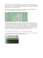
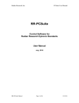
WEL 1-Wire Combo Module.
User Guide. Rev 1.0 - 11/23/09
The WEL 1-Wire Combo Module combines two remote 1-Wire functions:
An 8-channel Thermostat Sensor module
A 2-channel Pulse Counter module.
These modules operate independently, and only share a common PCB and 1-Wire connector.
These functions are described separately in the following text.
8-channel Thermostat Sensor module
On occasion, WEL users would like to be able to know WHY their HVAC system is working
when it does, rather than just watching passively, and trying to guess the cause. In these cases, the
real need is to be able to monitor the various “calls” being made by thermostats and other system
inputs. These calls are commonly made by switching 24VAC control circuits, so the WEL needed
a way to sense when 24VAC is present on a pair of wires. Since 24VAC is not compatible with
the WEL or the 1-Wire bus, a special input module was needed.
The WEL Combo Module can sense a wide range of input voltages by using optically isolated
input circuits. An On/Off indication is provided for each input. These independent inputs can
sense the presence/absence of AC or DC in the range of 9 to 24 volts. Since the inputs are
optically isolated, they can be connected to totally different pieces of equipment, without the
concern of ground loops or stray electrical paths causing problems. Each input comprises an LED
and current-limit resistor, so there IS a small impact on the signal being measured, so this must be
considered when used with more advanced digital HVAC controllers.
Thermostat Sensor hookup
The Combo Module communicates to the WEL using the 1-Wire bus, so the Black “Ground” and
Yellow “Bus” wires need to be connected. However, the Thermostat Sensor function does not
require any external power to operate, so it is NOT necessary to use the third “power” wire of the
1-wire bus. See the Pulse Counter section for more about the “Power” connection.
Each Thermostat input requires a pair of wires to be connected. 8 Pairs of input connectors are
provided in a set along the long edge of the board. Channels 1 and 8 are indicated at either end of
the connector block.
Typically the inputs will be wired in parallel with (across) the thermostat wires (eg: bridging C
and Y1). In a 24V system this will cause 6.6mA of current to flow though the Sensing LED.
Since this is not enough to active a relay, it will usually not have any impact on the normal
operation of the HAVC system.
However, in some digital systems, the current drawn by the sensing LED is enough to activate an
HVAC function. In this case, the two Combo Inputs terminals should be wired in series with the
thermostat control signal. This will require breaking the control path at some point and wiring it
in and out of the Combo Module input. One easy way to test this is to mount the Combo Module
next to the HVAC controller and move the incoming thermostat wire from the HVAC terminal to
one side of a channel on the Combo Board. Then run a wire from the other side of the channel
back to the original HVAC controller terminal. Now the signal passes through the Combo
Module. Just do this with control signals, not the common ground or power.
Thermostat Sensor software setup
Once the Combo Module is attached to the 1-Wire bus, it will be “found” next time the WEL
performs a bus scan. This will happen automatically the next time the WEL reboots, or it can be
performed manually for several of the WEL’s web pages. Just click the Scan Bus button.
When the WEL discovers the Thermostat inputs, it adds them to the device list as a block of 8
devices. The first device will be type 41 and the rest will be type 14. The 8 devices correspond to
input channels 1 to 8. With the default scaling, the resulting value for each input will be either 0
(no voltage sensed) or 1 (voltage is sensed).
The following screen capture is an example of how the Thermostat inputs might appear on your
device list. In this example, four inputs are active with names.
One final consideration is whether or not the On/Off state of the thermostat signal needs to be
reversed (flipped). Depending on how your HVAC controller is wired, it’s quite possible that
there will be 24VAC present if the thermostat is NOT calling for an action, and then this voltage
will go to 0V when the call is active. This simply means that you need to configure the WEL to
reverse the on/off indication. This can be done by re-calibrating this input. If you go to the
WEL’s Calibrate page and locate the input channel in question, simply set the Scale to –1.0 and
the offset to 1.0 This will have the effect of converting a 0 to a 1, and a 1 to a 0.
In the example above, ExHeat is set to “invert” the on/off condition of the input.
The photo below shows the wiring hookup for this example. Inputs 1 (R), 2 (O) & 3 (G) share a
common ground (Y), but input 5 is a dedicated pair of wires (B).
2 channel Pulse Counter.
If a user needs more pulse counter inputs than the WEL board provides, or if the pulse signals are
not located near the WEL, it’s desirable to be able to add additional channels on the 1-Wire sensor
bus. The Combo-Module does this.
Pulse Counter Sensor hookup
The Combo Module communicates to the WEL using the 1-Wire bus, so the Black “Ground” and
Yellow “Bus” wires need to be connected. The Pulse Counter function ALSO requires external
power to operate (to facilitate high speed counting), so it is necessary to use the third “power” wire
of the 1-wire bus, or to provide local power.
The Pulse counter hardware includes a 5V regulator and backup battery, so either raw DC or
Regulated 5V can be supplied to the board. This will depend on what you have available at that
location. Unless there is a compelling reason otherwise, I recommend having the WEL supply
Raw DC to the Combo Module, and using the Combo Module’s on-board regulator. This keeps
the WEL’s local 5V supply clean, and compensates for any voltage drop on the 1-Wire bus.
To do this, connect the RED bus wire to the WEL’s +V Raw Output terminal on J3, and set the
Combo Board’s Power Source Select jumper to 12V. This puts the regulator into the circuit.
The Combo Module provides a three-terminal screw-connector for hooking up the pulse inputs.
The center terminal is a shared Ground (GND), and the Pulse 1 (P1) and Pulse 2 (P2) inputs are on
either side (they are labeled on the PCB). The P1 and P2 inputs have 1K pull-up resistors (tied to
+5V), so to signal a pulse, the external hardware must short the input connector to GND.
Note that these inputs are NOT isolated, so care must be taken not to connect these inputs to
equipment that is connected to the mains electrical ground. This will turn the 1-WIRE bus into a
giant lightning rod. Eg: most PCs are grounded, but most Watt-meters are not.
Pulse Counter software setup
Once the Combo Module is attached to the 1-Wire bus, it will be “found” next time the WEL
performs a bus scan. This will happen automatically the next time the WEL reboots, or it can be
performed manually for several of the WEL’s web pages. Just click the Scan Bus button.
When the WEL discovers the Pulse Counter inputs, it adds them to the device list as a pair of
devices. The first device will be type 29 and the second one will be type 6. These correspond to
P1 and P2 respectively.
With the default scaling (Scale = 1.0 Offset = 0.0), these devices will read the number of pulses
counted each minute. NOTE: the values for these devices only update ONCE A MINUTE, so
don’t panic if you don’t see an immediate change. You can change the scale to convert the count
into any other engineering unit, like Gallons per hour, Watts or even RPM. You can also set the
Accumulation letter for either device (on the devices page) to calculate total Gallons or
WattHours. See the WEL user manual for more details on Accumulations.