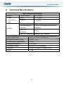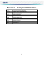
1
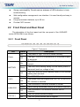
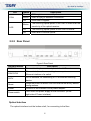
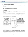
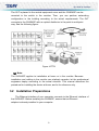
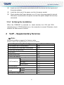
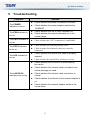
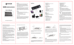
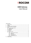
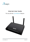
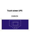
i
Contents
1
Safety Guidance...................................................................................................... 1
1.1
1.2
2
Electric Safety.................................................................................. 1
1.1.2
Device Position ................................................................................ 1
Safety Cautions .......................................................................................... 1
Overview ................................................................................................................. 2
2.1
2.2
3
Safety Check .............................................................................................. 1
1.1.1
Features and Functions.............................................................................. 2
Front Panel and Rear Panel ....................................................................... 3
2.2.1
Front Panel ...................................................................................... 3
2.2.2
Rear Panel....................................................................................... 4
Installing the OV904GP
3.1
3.2
3.3
................................................................................. 5
Product Networking Application.................................................................. 5
3.1.1
FTTH................................................................................................ 5
3.1.2
FTTB................................................................................................ 5
Installation Preparations ............................................................................. 6
Connecting the OV904GP
................................................................ 7
3.3.1
Connecting the Network Cable ........................................................ 7
3.3.2
Connecting the Fiber ....................................................................... 7
3.3.3
Connecting the Power Adapter and Power Cord ............................. 7
3.3.4
Verifying the Installation................................................................... 8
4
VoIP – Supplementary Services.............................................................................. 8
5
Troubleshooting ...................................................................................................... 9
6
Technical Specifications ........................................................................................ 10
i
1
Safety Guidance
1.1 Safety Check
Before installing the OV904GP device, you must check the following items.
1.1.1 Electric Safety
Ensure that there are no inflammable, conductive or moist objects around.
Check whether the cables are aged and whether other electrical appliances
are placed stably.
Check whether the alternating or direct input current is within the allowed
range of the device, whether the polarity of the direct current is correct, and
whether the earth line is properly connected.
1.1.2 Device Position
Because the running electric device easily generates heat, please ensure to
place the device in a well-ventilated environment.
Avoid direct sunshine, and do not place the device on a PC case.
Keep the device away from heat and water.
Check whether power supply is available. The input voltage fluctuation range
must be smaller than 10%. The power plug should not share one socket with
a hair drier, an iron or a refrigerator.
1.2 Safety Cautions
Read the user manual carefully before using the device.
Note all Cautions in the user manual and product guide.
Do not use any accessory that does not belong to the device without prior
consent of the manufacture, as it may cause fire or product damage.
Use the power adapter accompanied in the package.
Do not place any object on the device.
Keep the device dry, ventilated, rainproof, and clean.
During lightning weather, unplug the power plug and all connection cables, to
protect the device against lightning.
1
Clean the device using a soft and dry cloth rather than liquid or atomizers.
Power off the device before cleansing it.
Power off the idle device.
Keep the ventilation hole clean and prevent any object from dropping into the
device through it. Otherwise, it may cause short circuit and further cause
device damage or fire. Do not spray liquid on the surface of the device.
Do not open the case of the device, especially during device power-on.
Before plugging or unplugging the power, ensure that the power is off, thus
avoiding surge.
Be careful when unplugging the power, as the transformer may be very hot.
Cover the optical interface with fiber interface cap when it is not in use. Avoid
direct eye exposure to the laser emitted from the optical interface. Wear
safety glasses if possible, to protect your eyes.
Caution:
Please read the above safety guidance carefully before device use. Users
should assume responsibilities for any accidents due to incompliance with
the above instructions.
2
Overview
This chapter mainly describes functions and the structure of the OV904GP.
2.1 Features and Functions
The OV904GP is an GPON-based optical network unit (ONU). It contains the
community antenna television (CATV) module and built-in voice over Internet
protocol (VoIP) module. It provides network phone, high speed Internet access,
online video on demand (VOD), video conference, large file transmission service,
cable television service, and VoIP. The features of the OV904GP are as
follows:
Fast rate. Support up to 1.25 Gbps uplink and 2.5 Gbps downlink data
transmission rates.
2
Strong maintainability. Provide various statuses of LED indicators, to help
troubleshooting.
Web configuration management user interface. It is user-friendly and easy to
operate.
Long transmission distance, up to 20 km.
Provide CATV service.
2.2 Front Panel and Rear Panel
The description of the front panel and the rear panel of the OV904GP
series GPON ONU is as follows.
2.2.1 Front Panel
Figure 1 Front panel
LED
Status
On
Power
Off
On
BATTARY
Blinks
Off
On
CATV
LAN4/3/2/1
Off
The Ggv7.3U72A-52 is powered off or the power supply
is abnormal.
The ONU has a backup battery and the battery status is
normal.
The ONU has a backup battery but the battery status is
abnormal (such as: voltage is low).
The ONU does not have a backup battery or the backup
battery does not work.
The CATV RF interface is connected.
The system does not support the CATV RF, or the CATV
RF interface is disabled.
On
The connection of Ethernet interface is normal.
Blinks
Data is being transmitted through the Ethernet interface.
Off
POTS2/1
Description
The power of Ggv7.3U72A-52 works normally.
The connection of the Ethernet interface fails to
establish.
On
The VoIP phone service is ready.
Off
The VoIP phone service fails to register.
3
LED
PON
Status
ONU registers successfully.
Blinks
ONU is trying to establish connection.
Off
ONU fails to register.
Blinks
LOS
Description
On
The receiving optical power of the ONU is lower than the
sensitivity of the optical receiver.
Off
The receiving optical power of the ONU is normal.
On
ONU fails to receive optical.
2.2.2 Rear Panel
Figure 2 Rear Panel
Interface/Button
POTS1/2
LAN1/2/3/4
CATV
Reset
Power
Power switch
Description
Connect to telephone set and provide the VoIP service.
Ethernet interface, for connecting to a computer or an
Ethernet interface of a switch.
CATV interface, for connecting to TV or another receiving
device.
Press the button to reboot ONU and restore the factory default
configurations.
Connect to the interface of the power adapter.
Turn on/off the power supply of the OV904GP (at the
right side of Power interface).
Optical Interface
The optical interface is at the bottom shell, for connecting to the fiber.
4
3
Installing the OV904GP
The chapter describes the required installation operations before you use the
OV904GP for the first time.
3.1 Product Networking Application
3.1.1 FTTH
Fiber to the Home (FTTH) means to install the ONU to residences or enterprise
buildings.
The optical line terminal (OLT) is placed in the central equipment room. The
OV904GP can be placed in the home of a user, or it can provide connection
for the user through the Ethernet interface, according to the user requirement. The
OLT connects to the OV904GP with an optical distributor in the
point-to-multipoint way. See the following figure.
Figure 3 FTTH
3.1.2 FTTB
Fiber to The Building (FTTB) is a type of broadband access mode based on
optimized high speed optical LAN technology. It realizes broadband access for the
user by fiber to the building and cable to the home, which is the most reasonable,
practical, and cost-effective broadband access method.
5
The OLT is placed in the central equipment room and the OV904GP can be
mounted to the switch in the corridor. Then, you can perform networking
configuration in the building according to the actual requirements. The OLT
connects to the OV904GP with an optical distributor in the point-to-multipoint
way. See the following figure:
Figure 4 FTTB
Note:
The OV904GP applies to installation at home or in the corridor. Because
installation and cabling in the corridor are relatively complex, let the professional
engineers deploy according to the actual situation. This manual describes the
procedure for installing the device at home, and is for reference only.
3.2 Installation Preparations
The Ethernet interface of your computer connects to the Ethernet interface of
the OV904GP. Before installing the OV904GP, ensure that an Ethernet
adapter is already installed in your computer.
6
3.3 Connecting the OV904GP
3.3.1 Connecting the Network Cable
(1)
Use one end of a network cable to connect the Ethernet interface on the rear
panel of the OV904GP.
(2)
Use the other end of the network cable to connect the Ethernet interface of the
computer.
3.3.2 Connecting the Fiber
Caution:
When a fiber is not in use, ensure to cover the optical interface of the
OV904GP and the dust cap of the optical fiber. Prevent dust pollution or
water immersion, which may lead to unavailable fiber and optical interface of
the OV904GP.
If fibers need to be fixed during parallel cabling, do not fasten the fibers too
tight. Avoid fiber extrusion, which may lead to increase of fiber material or
unavailable fiber.
Before connecting the OV904GP to the fiber, you must set up the fiber. To set
up the fiber, do as follows:
(1)
Remove the screws from the cover board.
(2)
Remove the cover board.
(3)
Insert one end of the optical into the optical adapter.
(4)
Wind the fiber on the patch panel, and reserve fiber of suitable length to be
(5)
Fix the cover board.
extracted from the hole on the cover board.
(6)
Fasten the screws on the cover board.
(7)
Mount the rubber plug.
After setting up the fiber, connect the fiber from the optical interface at the bottom
shell to the optical interface on the wall.
3.3.3 Connecting the Power Adapter and Power Cord
(1)
Connect the output end of the power adapter included in the device package
to the input end of the power supply of the OV904GP.
7
(2)
Insert one end of the power cord attached with the device into the input end of
the power adapter.
(3)
(4)
Insert the other end of the power cord into the power socket.
Check whether the Power indicator is on. If it is on, the power supply is normal.
Otherwise, check whether the power cord and the power adapter are correctly
connected.
3.3.4 Verifying the Installation
When the OV904GP is powered on, check whether the LOS and PON
indicators are on. If PON indicator is on, the connection is normal. Otherwise, check
whether the fiber access is correct.
4
VoIP – Supplementary Services
Note:
Soft-switch platform supports the feature codes.
Feature codes of the supplementary services are as follows:
Supplementary Service Type
Call transfer with no consultation
Feature Code
#90
Call transfer with third-party consultation
#91
Three-way conferencing
-
Call return
*69
Redial when busy
#5
Cancel call waiting
*70
Call forwarding
Unconditional
*72
When busy
*74
No reply
*75
Cancellation
*73
Anonymous call
Enable
*77
block
Cancel
Do not disturb
*78
*87
Anonymous outgoing call
*67
8
5
Troubleshooting
Symptom
The POWER
indicator is not on
The PON indicator is
not on
The CATV indicator is
not on
The POTS indicator
is not on
The LOS indicator is
not on
Solution
Check whether the power connection is correct.
Check whether the power adapter matches the
OV904GP
Check whether the SN of ONU matches OLT.
Check whether the optical attenuation is in the
normal range.
Check whether the CATV connection is established.
Check whether you can ping through ONU.
Check whether the telephone cables are correctly
connected.
Check whether the optical fiber cable is properly
inserted.
Check whether the optical fiber connector is clean.
Check whether the OV904GP is authorized by
the carrier.
Check whether the network cables included in the
device package are used.
The LAN1/2/3/4
Check whether the network cable connection is
indicators are not on
normal.
Check whether the indicator of the network adapter is
on.
Check whether the network adapter works in the
normal state.
9
6
Technical Specifications
Main Technical Specifications
Standard
GPON standard
Data
Uplink
transmission
Downlink
ITU-T G.984
1.25Gbps
2.5Gbps
rate
Interface
One optical interface
Single mode
Four fast Ethernet
RJ-45, 10/100 Mbps, MDI/MDIX self
interfaces
adaptation
Two POTS
RJ-11
interfaces
One CATV interface
Standard CATV interface
Physical Characteristics and Environment Requirements
Power adapter input
100 V~240 V AC, 50 Hz~60 Hz
Whole-device power supply
12V DC, 1.5A
Standard power consumption
< 16 W
Operating temperature
-10˚C~55˚C
Operating humidity
10%~90%, non-condensing
Dimension
L x W x H: 232mm x 168mm x 45mm
Weight
< 1 kg
10
Appendix A
Acronyms and Abbreviations
CATV
Community Antenna Television
GPON
Gigabit Passive Optical Network
FTTB
Fiber to the Building
FTTH
Fiber to the Home
OLT
Optical Line Terminal
ONU
Optical Network Unit
PON
Passive Optical Network
QoS
Quality of Service
VLAN
Virtual Local Area Network
VoIP
Voice over IP
11
12