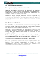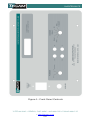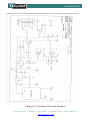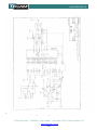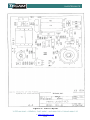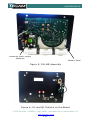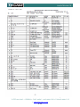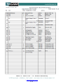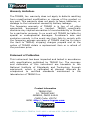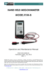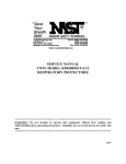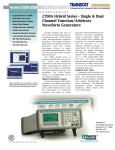
1
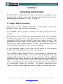
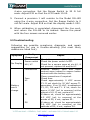
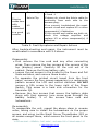
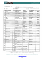
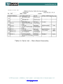
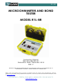
R1L-BR MICROOHMMETER AND BOND TESTER MODEL R1L-BR Instruction Manual PN# R1L-BR-900-01 Publication Date: December 2012 REV. F REPRODUCTION AND DISTRIBUTION OF THIS TECHNICAL MANUAL IS AUTHORIZED FOR US GOVERNMENT PURPOSES. TEGAM PROPRIETARY INFORMATION. NOTE: This User’s Manual was as current as possible when this product was manufactured. However, products are constantly being updated and improved. To ensure you have the latest documentation, refer to www.tegam.com 10 TEGAM WAY • GENEVA, OHIO 44041 • 440-466-6100 • FAX 440-466-6110 • [email protected] TABLE OF CONTENTS TABLE OF CONTENTS 1. INSTRUMENT DESCRIPTION Purpose ............................................................... 1-1 Performance Characteristics ................................... 1-1 Description of Equipment ....................................... 1-2 List of Items Furnished .......................................... 1-3 Storage and Shipping Requirements ........................ 1-3 2. PREPARATION FOR USE AND INSTALLATION Unpacking and Inspection ...................................... 2-1 Preparation for Use................................................ 2-1 3. OPERATING INSTRUCTIONS Pushbutton Functions ............................................ 3-1 General Theory of Operation ................................... 3-2 4. PRINCIPLES OF OPERATION 5. MAINTENANCE Inspection ............................................................ 5-1 Cleaning .............................................................. 5-1 Test Equipment required for Calibration and Repair ... 5-1 Calibration ........................................................... 5-2 Troubleshooting .................................................... 5-3 Table 2: Fault Symptoms and Repair Actions ........ 5-3 Preparation for Shipment ....................................... 5-5 Overhaul Instructions ............................................ 5-5 Figure 1: Front Panel Controls ............................. 5-6 Figure 2: Constant Current Section ...................... 5-7 Figure 3: Digital Section ..................................... 5-8 Figure 4: Parts Layout ........................................ 5-9 Figure 5: R1L-BR Assembly .............................. 5-10 Figure 6: U1 and Q1 Position on the Board ......... 5-10 Table 3: Parts List –PC Board Assembly.............. 5-11 Table 4: Parts List – PC Board Assembly............. 5-12 Table 5: Parts List – Main Board Assembly .......... 5-13 Table 6: Parts List – Main Board Assembly .......... 5-14 6. SERVICE INFORMATION Preparation for Repair or Calibration Service ............. 6-1 10 TEGAM WAY • GENEVA, OHIO 44041 • 440-466-6100 • FAX 440-466-6110 • [email protected] TABLE OF CONTENTS Expedite Repair and Calibration Form ...................... 6-2 Warranty.............................................................. 6-3 10 TEGAM WAY • GENEVA, OHIO 44041 • 440-466-6100 • FAX 440-466-6110 • [email protected] INSTRUMENT DESCRIPTION SECTION 1 INSTRUMENT DESCRIPTION INTRODUCTION 1.1 Purpose The Model R1L-BR is a digital Microohmmeter / Bond Tester with full scale ranges from 2 mΩ to 20 Ω. The resistance reading is displayed on a 3½ digit liquid crystal display on the front panel. An over-range condition is indicated as a "1" followed by three blank digits (the decimal point is also displayed in its normal position for the range selected). A bench top version, Model R1L-B is also available, which is electronically identical to model R1L-BR, but it has an open front panel rather than a rugged case as the enclosure. 1.2 Performance Characteristics This is a range-selection instrument, with a rotary 5 range selector switch. Range Full Scale (Ω) Resolution (Ω) Test Current Peak (A) 1 2 3 4 5 1.999 m 19.99 m 199.9 m 1.999 19.99 1µ 10 µ 100 µ 1m 10 m 1.4 140 m 14 m 1.4 m 140 µ Table 1: Specifications Accuracy: Accuracy on all ranges: ± (0.25% of reading + 1 count), when powered from the batteries only. 10 TEGAM WAY • GENEVA, OHIO 44041 • 440-466-6100 • FAX 440-466-6110 • [email protected] 1-1 INSTRUMENT DESCRIPTION 1.3 Description of Equipment Physical: The circuitry is enclosed in a rugged bench top case. Dimensions: 127 mm (5”) x 254 mm (10”) x 228 mm (9”). Weight is 3 kg (6.7 lb). Controls and connectors are of a size and spacing such that the instrument may be operated while wearing safety gloves. Electrical: The R1L-BR is powered by an internal battery consisting of three rechargeable NiCad ‘C’ cells (3000 mAh) with a built-in charger. Input power for the charger is 90 VAC to 250 VAC at 50 Hz or 60 Hz. Charging power is supplied via a removable line cord; one end of which plugs into a line filter on the front of the R1L-BR, and the other end being a standard three-pin grounded line plug. Input Protection: The R1L-BR will not be damaged by a signal of 1 Vp-p applied across any pair of input terminals. Environmental: This unit will operate over a temperature range from 0 °C to 50 °C, 75% RH non-condensing, up to 3050 m altitude. Front Panel Controls and Displays (See figure 1) RANGE Switch. The rotary 5 range selector switch may be used to step through all five ranges. POWER Switch. Used to turn the power on or off to the instrument. DISPLAY is a 3 ½ digit, displaying readings from 1.999 to 199.9. Four binding posts for connection of test leads are marked +I, +E, -E, and -I. Proper connections to the resistor under test are described in Section 3.2 below. 10 TEGAM WAY • GENEVA, OHIO 44041 • 440-466-6100 • FAX 440-466-6110 • [email protected] 1-2 INSTRUMENT DESCRIPTION WARNING DO NOT TOUCH THE BINDING POSTS WHEN THEY ARE CONNECTED TO EXTERNAL CIRCUITS. LETHAL VOLTAGES MAY BE PRESENT AT THESE POSTS. 1.4 List of Items Furnished 1 each Model R1L-BR with power cord 3 each rechargeable battery cells 1 each R1L-BR Instruction Manual 1.5 Storage and Shipping Requirements Standard precautions which apply to electronic test instruments should be followed. A hard mechanical shock, such as from dropping the R1L-BR, could damage the liquid crystal display. Care should be taken to prevent damage to associated cables. The R1L-BR should be stored in a relatively dust-free environment. Remove the battery cells for inactive storage of 30 days or more. Temperature: -40 °C to +71 °C. Relative humidity: 0 to 100%, non-condensing. Altitude: 4570 m See Section 5.7 below for shipping requirements. 10 TEGAM WAY • GENEVA, OHIO 44041 • 440-466-6100 • FAX 440-466-6110 • [email protected] 1-3 PREPARATION FOR USE AND INSTALLATION SECTION 2 PREPARATION FOR USE AND INSTALLATION 2.1 Unpacking and Inspection Upon receipt, the R1L-BR and accessories should be carefully unpacked and removed from the shipping container. Separate the units from the packing material and inspect both the instrument and the accessories for any external damage. If any dents, broken, or loose parts are seen, do not use the equipment. Notify the shipping company immediately and follow their instructions as to how to proceed. Note that the instrument is shipped with its battery removed. Unwrap the 3 cells which comprise the battery. Check that all items are present. If any items are missing, notify the shipper if this is a new instrument. If not new, contact the previous user to locate the missing item(s). 2.2 Preparation for Use Battery Installation Be sure the power line cord is disconnected. Check that the Power Switch is in the OFF position. Remove the four screws at the corners of the R1L-BR’s top (control/display) panel. Carefully lift the unit out of its cabinet. Place the unit upside down on a surface which will not mar or damage the control/display panel. WARNING DO NOT CONNECT THE AC LINE CORD PRIOR TO REMOVING THE UNIT FROM ITS CASE OR WHILE THE UNIT IS OUT OF ITS CASE, OR ELSE THE MAINS VOLTAGE WILL PRESENT A POSSIBLE SHOCK HAZARD. 10 TEGAM WAY • GENEVA, OHIO 44041 • 440-466-6100 • FAX 440-466-6110 • [email protected] 2-1 PREPARATION FOR USE AND INSTALLATION CAUTION BE SURE TO OBSERVE THE PROPER POLARITY WHEN INSERTING THE BATTERY CELLS OR DAMAGE MAY RESULT. Insert the battery cells, one at a time, in accordance with the polarity indications marked on both the battery cell and the battery holder. Insert the positive end of the battery cells first. After installing the cells, reinstall the instrument in its case and secure the four corner screws. Power Up Plug the power cord into the R1L-BR front panel receptacle, and plug the other end into a standard AC outlet. For battery operation (with charged battery cells), this step is omitted. Turn on the POWER rotary switch. Note that this switch turns on both line and battery power. Charging the Battery Cells Prior to battery operation, it is recommended the R1L-BR Microohmmeter be plugged into AC power for at least 14 hours to charge the battery cells. To charge the battery cells, the Power Switch must be turned ON, and the Range Switch should be set to 20 Ω. With the Range Switch set to lower ranges, the charge rate decreases and the batteries will be discharged, especially on the 2 mΩ range, even with no resistance connected to the instrument. (However, the discharge rate in this range will permit operation for at least 14 hours with no resistance connected.) WARNING ALTHOUGH THE FRONT PANEL IS NORMALLY GROUNDED VIA THE GROUND PIN OF THE POWER CABLE, IF THIS CONNECTION IS FAULTY AND IF THE HIGH SIDE OF THE POWER CABLE IS SHORTED TO THE PANEL, THE PANEL COULD POSSIBLY HAVE MAINS VOLTAGE ON IT; SO DO NOT TOUCH THE PANEL WHEN AC POWER IS CONNECTED. 10 TEGAM WAY • GENEVA, OHIO 44041 • 440-466-6100 • FAX 440-466-6110 • [email protected] 2-2 OPERATING INSTRUCTIONS SECTION 3 OPERATING INSTRUCTIONS The R1L-BR is designed for field or bench-top operation. Use appropriate cables connecting their terminations to the four binding posts marked +I, +E, -E, and -I. 3.1 Rotary Switch Functions Operation of the Model R1L-BR is essentially extremely simple. There are only two switches. The RANGE rotary switch manually scrolls through the five ranges. Full scale on any range may be described as 2,000 (actually 1,999), since this is a 3½ digit meter. If the readings are exceeding 1,999 counts, step to the next higher range. If the readings are less than 2,000 counts, step down a range, so that it will read 1,999 counts, or less. The decimal point is located automatically for the correct reading. If the selected range is too low for the value of the resistor under test, the display will show over-range. The POWER rotary switch turns on the power to operate the unit or turns off the power to the unit. The appearance of the display will show that power is on; absence of the display indicates that either power is off, batteries are discharged, or there is some malfunction. Note that when power is turned off, it may take several seconds to discharge circuit capacity to completely blank the display. The black markings seen have no effect and disappear when power is turned back on. 10 TEGAM WAY • GENEVA, OHIO 44041 • 440-466-6100 • FAX 440-466-6110 • [email protected] 3-1 OPERATING INSTRUCTIONS 3.2 General Theory Of Operation Measurement Principle A 4-terminal measurement method is used to determine the resistance of the item under test. This method allows the accurate measurement of low values of resistance in spite of the other resistances present in the connection leads. A known current is supplied to the item under test via two wire leads connected to the +I and -I binding posts on the R1LBR Microohmmeter front panel. Two other wire leads connected to the +E and -E binding posts on the R1L-BR front panel sense the voltage developed across the resistance under test due to the supplied known current. The R1L-BR then calculates the resistance of the item under test utilizing Ohm's law, and displays it on a 3 ½ digit display. Kelvin Klip Cable Description A Kelvin clip consists of two opposing jaws of an alligator style clip which are insulated from each other, so one jaw may be used to connect a source of current to the resistance under test, and the other jaw used to measure the voltage at the test point. The two jaws are spring loaded to clamp onto a cylinder of ½ inch diameter or less. WARNING OPERATING THE R1L-BR MICROOHMMETER AND TAKING RESISTANCE MEASUREMENTS ON A POWERED OR ENERGIZED COMPONENT COULD CAUSE SERIOUS HARM TO THE OPERATOR AND/OR DAMAGE THE R1L-BR. BE SURE THE ITEM TO BE MEASURED IS DISCONNECTED FROM OTHER COMPONENTS AND APPARATUS. If the battery cells have not been installed, refer to section 2.2. Battery only operation will result in the most stable and accurate readings. The R1L-BR may be operated while charging the batteries, however it will not conform to specifications in this configuration. 10 TEGAM WAY • GENEVA, OHIO 44041 • 440-466-6100 • FAX 440-466-6110 • [email protected] 3-2 OPERATING INSTRUCTIONS NOTE: The amount of current available for charging the battery decreases as lower resistance ranges are selected. In the 2 mΩ range, the current supplied to the resistance under test exceeds the charging current, and the battery will be drained. To obtain the best accuracy, allow the R1L-BR to warm up for 15 to 30 minutes on the 20 Ω range before making measurements. Even if in battery operation, this will not cause appreciable battery discharge. In any case, a minimum warm-up of 30 seconds is advised. Using the Kelvin-Clip cables Plug one Kelvin-Clip cable dual banana plug across the +E and +I binding posts, and plug the other Kelvin-Clip cable dual banana plug across the -E and -I binding posts. Note that in both cases, the small "I" marked on the dual banana plug should go into the respective I binding post. If Kelvin-Clip cables are not used, a pair of shielded cables may be utilized. As occurs in the Kelvin-Clip cables in the above paragraph, one cable should have its shield connected to the “+I” binding post and its center conductor connected to the +E binding post. Similarly, the other cable should have its shield connected to the -I binding post and its center conductor to the -E binding post. It is also recommended that the resistance of the cables should not exceed 1 Ω. NOTE: Particularly in the 2 mΩ range, where a test current of approximately 1 . 5 A is used, excessive lead resistance will prevent an accurate measurement. Set the Range Switch to the desired measurement range and read the resistance on the liquid crystal display. If the resistance is higher than the selected range, the display will show a "1" and three blank digits, indicating over-range. The decimal point will also appear in the proper location for the selected range. 10 TEGAM WAY • GENEVA, OHIO 44041 • 440-466-6100 • FAX 440-466-6110 • [email protected] 3-3 OPERATING INSTRUCTIONS After prolonged operation on battery power, when the battery voltage approaches the end of its useful range, the "LO BAT" indicator will be seen on the display. Although the battery cells are not fully discharged and they will not be damaged by additional use, this is a warning to the operator that the battery cells need to be charged. Use of HTP-100 probes with R1L-BR 1. Connect the BLUE spade lug from the LEFT HTP-100 Probe to the RED E+ terminal of the R1L-BR. 2. Connect the RED spade lug from the LEFT HTP-100 Probe to the RED I+ terminal of the R1L-BR. 3. Connect the WHITE spade lug from the RIGHT HTP-100 Probe to the BLACK E- terminal of the R1L-BR. 4. Connect the BLACK spade lug from the RIGHT HTP-100 Probe to the Black I- terminal of the R1L-BR. 5. Hold the RED HTP-100 Probe in your left hand and the WHITE HTP-100 Probe in your right hand, and push the probe points against the surface to be measured with sufficient force to cause the points to retract slightly. 10 TEGAM WAY • GENEVA, OHIO 44041 • 440-466-6100 • FAX 440-466-6110 • [email protected] 3-4 PRINCIPLES OF OPERATION SECTION 4 PRINCIPLES OF OPERATION The internal power supply uses a switching power supply to accept worldwide line voltages 50/60 Hz. A filter capacitor, and constant current regulator Ul complete the power supply. R1 sets the value of the constant current to approximately 500 mA, D5 is used to isolate the AC power for the battery. D7 serves to clamp the voltage to less than 5 V when the battery is disconnected. Q1 regulates the constant current through the resistance under test. This current is measured by the I x R drop across R12, etc., depending upon the range selected. For all ranges, the I x R drop is summed with a portion of the 3.0 V reference signal existing between pins 1 and 32 of U4, the Digital Voltmeter (DVM) IC. The 3.0 V reference is effectively divided by 2 by the network of R8, R9, R10 and R11, and added to the I x R drop across R12, etc., so that this I x R drop is maintained at 1.5 V. U2, pins 1, 2, and 3, amplifies the error signal, driving Q2, which controls Q1 to reduce the error signal. The I x R drop is thus regulated, so that the test current delivered to the +I binding post remains constant. If the current tends to increase, pin 2 goes positive with respect to pin 3; this reduces the output from pin 1 to drive transistor Q2, which reduces the drive to Q1 and thereby reduces the current out of Q1, thus regulating this current. Current on the 2 mΩ range is approximately 1.5 A. Current on the other ranges decreases by 10:1 on each range because the resistor networks are adjusted to increase by 10:1 for each succeeding range. Note that the ratio of currents between ranges is precisely 10:1, but the actual value of current is not held exactly to 1.5 A, etc., because the DVM is calibrated to read the correct resistance value regardless of drift of the reference voltage and the resulting current. The section of U2 employing pins 5, 6, and 7 is a unity gain follower to provide a voltage equal to that present at the +I 10 TEGAM WAY • GENEVA, OHIO 44041 • 440-466-6100 • FAX 440-466-6110 • [email protected] 4-1 PRINCIPLES OF OPERATION binding post, without taking any appreciable current from the output circuit. The section of U2 utilizing pins 8, 9, and 10 checks the battery voltage by checking the voltage of pin 32 of U4. The voltage at this pin is 3.0 V below the battery voltage. Therefore, when the battery voltage drops below 3.0 V, the voltage at this pin goes negative. The output of this section of U2 then goes high, generating a Low Battery (LO BAT) signal for the liquid crystal display (LCD). The voltage signal from the voltage binding posts is fed into the chopper amplifier U3. This amplifier has a gain of 50, putting the signal into U4, the DVM IC, at 0.15 V full scale. U4 drives the LCD, U6. U7 controls the indicated decimal points on the LCD and the LO BAT indication. U5 provides -3.6 V power to the amplifiers. U6 is a 3½ digit liquid crystal display, driven segment by segment by U7. S2B provides the proper logic levels to the quad exclusive-OR gate U6 to locate the decimal point on the display. R33, R34, and R35 are pull-down resistors. 10 TEGAM WAY • GENEVA, OHIO 44041 • 440-466-6100 • FAX 440-466-6110 • [email protected] 4-2 MAINTENANCE SECTION 5 MAINTENANCE 5.1 Inspection These units should be inspected semi-annually. Cables should be periodically inspected to make sure they are in good condition. Check that the switches turn smoothly. Check all four binding posts to ensure that they operate smoothly. No other maintenance is required, other than to keep the battery charged through power line operation. Charging should be done for at least 14 hours after long periods (several months) of storage or after considerable use on battery power. 5.2 Cleaning The instrument should be cleaned periodically, as is necessary, using mild soap and a damp cloth both followed by second damp rinsing cloth. Clean the LCD window using a soft cloth moistened with water or "Windex" type window cleaner. DO NOT use common paper towel products as some brands may contain fibers which could scratch the display window. DO NOT apply significant pressure to the LCD window as it could separate from the front panel. DO NOT use alcohol, solvents, or harsh chemicals to clean the LCD window. 5.3 Test Equipment and Tools Required for Calibration and Repair Calibration of the R1L-BR is recommended on a yearly basis, and is done at a temperature of 23 °C ± 1 °C. Precision four terminal resistors with accuracy of 0.01% or better: 1 mΩ and 10 Ω 10 TEGAM WAY • GENEVA, OHIO 44041 • 440-466-6100 • FAX 440-466-6110 • [email protected] 5-1 MAINTENANCE An oscilloscope: Hitachi V-1050F or equivalent. A standard digital multimeter: (accuracy of 0.02% of reading or better) voltage ranging from 100 mV. HP/Agilent 34401A or equivalent. Screwdrivers: Medium Phillips and small slotted for trim-pot adjustment. 5.4 Calibration CAUTION SAFETY PRECAUTIONS MUST BE TAKEN WHEN HANDLING THIS INSTRUMENT WHEN THE LINE CORD IS PLUGGED IN AND THE R1L-BR HAS BEEN REMOVED FROM ITS CASE, TO ENSURE THAT CONTACT IS NOT MADE WITH THE AC POWER CONNECTIONS OR OTHER POTENTIALLY HARMFUL POINTS. FAILURE TO OBSERVE PROPER SAFETY PRECAUTIONS MAY CAUSE SERIOUS HARM TO THE OPERATOR AND/OR DAMAGE THE R1L-BR. 1. Prior to calibration, the battery should be fully charged as per section 2.2. Allow at least 1 hour warm-up of the R1L-BR before calibration. 2. Check the location of the trim pots on the Parts Layout Drawing, figure 4. 3. Connecting a shorting bus wire loop, starting at the -I binding post, connecting to the -E binding post, and then to the +E binding post. This prevents the E terminals from measuring any I x R drop across the wire. Set the Range Switch to 20 Ω full scale. Adjust R26 for a zero reading on the LCD. Note the display reading may vary by ± 1 count. Also note that this instrument resolves 1 µV per count, and you should therefore avoid heating the shorting wire with your fingers, or thermally generated voltages may cause considerable error. 4. Connect a precision 10 Ω resistor to the R1L-BR using the 10 TEGAM WAY • GENEVA, OHIO 44041 • 440-466-6100 • FAX 440-466-6110 • [email protected] 5-2 MAINTENANCE 4-wire connection. Set the Range Switch to 20 Ω full scale. Adjust R32 so that the LCD reads 10.00. 5. Connect a precision 1 mΩ resistor to the Model R1L-BR using the 4-wire connection. Set the Range Switch to 2 mΩ full scale. Adjust R18 so that the display reads 1.000. 6. When calibration is completed, disconnect the line cord, and return the R1L-BR to its cabinet. Secure the panel with the four screws removed earlier. 5.5 Troubleshooting Following are possible symptoms, diagnosis, and repair suggestions for use in trouble-shooting (the most likely causes are listed first). Symptom No Display Faulty Component Power cord Power switch U6 / U7 Connections Fuse U1 Battery won’t charge R1 D5 Repair Check the power cord is plugged in. Check the power switch is ON. Check for a square wave at pin 40, if not present, replace U6 and/or U7. Remove battery cells and bend contact arms inward to ensure better contact with the battery cells. Clean connections if required. Check fuse. Check approximately 9 VDC across C1. If not check for 20 VAC across T1 secondary. If no 20 VAC, troubleshoot C1, D1, D2 and T1. If ok, check for aprox. 6 VDC (ref. to common) at the output of U1. If not, replace U1. If above ok, check for approximately 4.5 VDC (ref. to common) at the anode of D5, if not, replace R1. If above ok, check for approximately 3.6 VDC (ref. to common) at the cathode of D5, if not, replace D5. 10 TEGAM WAY • GENEVA, OHIO 44041 • 440-466-6100 • FAX 440-466-6110 • [email protected] 5-3 MAINTENANCE Current o/p Display reads zero with cables connected to a good resistor Kelvin Clip U2 U3 Check for proper current o/p between +I and -I. If above ok, check the Kelvin cable for continuity from each side to the banana plug. If no current, troubleshoot the const. current circuit and replace U2 or other component(s) if defective. If the current and cables are both ok, check the voltage amplifier and replace U3 or other component(s) if defective. Table 2: Fault Symptoms and Repair Actions After trouble-shooting and repair, the instrument must be recalibrated in accordance with 5.4 above. Disassembly First remove the line cord and any other connecting wires. Then remove the four screws at the corners of the top (display) panel. Carefully lift the unit out of its cabinet. Remove the three battery cells. Loosen the set screws in the knobs for the Power and Full Scale switches, and remove these knobs. To separate the printed circuit board from the front panel, remove the four screws appearing in a rectangular pattern around the LCD and control switches. DO NOT remove a fifth screw to the lower right of the Power Switch. This screw is a heat sink connection for the transistor Q1. Remove the four screws that secure the battery plate along with their spacers (one screw goes through the battery holder). 2 of the screws have nuts and lockwashers. Re-assembly To reassemble the unit, repeat the above steps in reverse order, taking care to install the lockwashers on the proper screws, and using Loctite Small Screw Threadlocker 222 on all screws except those, which secure the front panel to the case. 10 TEGAM WAY • GENEVA, OHIO 44041 • 440-466-6100 • FAX 440-466-6110 • [email protected] 5-4 MAINTENANCE 5.6 Preparation for Shipment The original shipping carton is not reusable. Remove the battery cells prior to shipment (or inactive storage of 30 days or more) and package them separately. Disassemble the R1L-BR as per section 5.5, and extract the negative end of the battery cells first. Packaging must provide sufficient resilient material, in accordance with standard packaging practices, to prevent excessive shock to the power supply and display during shipment. 5.7 Overhaul Instructions The R1L-BR is an all solid-state unit and requires no periodic overhaul, other than routine cleaning, inspection of cables per section 5, and calibration per section 5.4. However, some disassembly is required to remove and install the batteries. This level of disassembly is detailed in section 2.2 and battery cells should be removed at the negative end first. Tools and test equipment used for disassembly, calibration, and troubleshooting of the R1L-BR are listed in section 5.3. Troubleshooting suggestions are given in section 5.5. The only component expected to require replacement is the battery. The battery designation is listed on the Replacement Parts List, with battery cell removal and installation instructions given in section 2.2. 10 TEGAM WAY • GENEVA, OHIO 44041 • 440-466-6100 • FAX 440-466-6110 • [email protected] 5-5 MAINTENANCE Figure 1: Front Panel Controls 10 TEGAM WAY • GENEVA, OHIO 44041 • 440-466-6100 • FAX 440-466-6110 • [email protected] 5-6 TEGAM, INC. MAINTENANCE Figure 2: Analog Board Schematic Figure 2: Constant Current Section 10 TEGAM WAY • GENEVA, OHIO 44041 • 440-466-6100 • FAX 440-466-6110 • [email protected] 5-7 TEGAM, INC. MAINTENANCE Figure 3: Battery Charger Schematics Figure 3: Digital Section 10 TEGAM WAY • GENEVA, OHIO 44041 • 440-466-6100 • FAX 440-466-6110 • [email protected] 5-8 MAINTENANCE TEGAM, INC. Figure 4: Parts Layout 10 TEGAM WAY • GENEVA, OHIO 44041 • 440-466-6100 • FAX 440-466-6110 • [email protected] 5-9 MAINTENANCE Switching Power Supply Assembly Battery Panel Figure 5: R1L-BR Assembly Q1 U1 Figure 6: U1 and Q1 Position on the Board 10 TEGAM WAY • GENEVA, OHIO 44041 • 440-466-6100 • FAX 440-466-6110 • [email protected] 5-10 MAINTENANCE TEGAM, Inc. Geneva, Ohio Figure 5: Main Board Parts Layout Table 3: Parts List – PC Board Assembly 10 TEGAM WAY • GENEVA, OHIO 44041 • 440-466-6100 • FAX 440-466-6110 • [email protected] 5-11 MAINTENANCE TEGAM, Inc. Geneva, Ohio Figure 6: Functional Block Diagram Table 4: Parts List – PC Board Assembly 10 TEGAM WAY • GENEVA, OHIO 44041 • 440-466-6100 • FAX 440-466-6110 • [email protected] 5-12 MAINTENANCE TEGAM, Inc. Geneva, Ohio Fuse, 1/4 Amp, 3AG 312.250 Table 5: Parts List – Main Board Assembly 10 TEGAM WAY • GENEVA, OHIO 44041 • 440-466-6100 • FAX 440-466-6110 • [email protected] 5-13 MAINTENANCE TEGAM, Inc. Geneva, Ohio Table 6: Parts List – Main Board Assembly 10 TEGAM WAY • GENEVA, OHIO 44041 • 440-466-6100 • FAX 440-466-6110 • [email protected] 5-14 SERVICE INFORMATION SECTION 6 SERVICE INFORMATION Preparation for Calibration or Repair Service Once you have verified that the cause for R1L-BR malfunction cannot be solved in the field and the need for repair and calibration service arises, contact TEGAM customer service to obtain an RMA, (Returned Material Authorization), number. You can contact TEGAM customer service via the TEGAM website, www.tegam.com or by calling 440.466.6100 (All Locations) OR 800.666.1010 (United States Only). The RMA number is unique to your instrument and will help us identify you instrument and to address the particular service request by you which is assigned to that RMA number. Of even importance, a detailed written description of the problem should be attached to the instrument. Many times repair turnaround is unnecessarily delayed due to a lack of repair instructions or of a detailed description of the problem. This description should include information such as measurement range, and other instrument settings, type of components being tested, are the symptoms intermittent?, conditions that may cause the symptoms, has anything changed since the last time the instrument was used?, etc. Any detailed information provided to our technicians will assist them in identifying and correcting the problem in the quickest possible manner. Use a copy of the Repair and Calibration Service form provided on the next page. Once this information is prepared and sent with the instrument to our service department, we will do our part in making sure that you receive the best possible customer service and turnaround time possible. 10 TEGAM WAY • GENEVA, OHIO 44041 • 440-466-6100 • FAX 440-466-6110 • [email protected] 6-1 SERVICE INFORMATION Expedite Repair & Calibration Form Use this form to provide additional repair information and service instructions. The Completion of this form and including it with your instrument will expedite the processing and repair process. RMA#: Instrument Model #: Company: Phone Number: Serial Number: Technical Contact: Additional Contact Info: Repair Instructions: Evaluation Repair & Calibration Calibration Only Z540 Repair Only Detailed Symptoms: Include information such as measurement range, instrument settings, type of components being tested, is the problem intermittent? When is the problem most frequent?, has anything changed with the application since the last time the instrument was used?, etc. 10 TEGAM WAY • GENEVA, OHIO 44041 • 440-466-6100 • FAX 440-466-6110 • [email protected] 6-2 SERVICE INFORMATION Warranty TEGAM, Inc. warrants this product to be free from defects in material and workmanship for a period of one year from the date of shipment. During this warranty period, if a product proves to be defective, TEGAM Inc., at its option, will either repair the defective product without charge for parts and labor, or exchange any product that proves to be defective. TEGAM, Inc. warrants the calibration of this product for a period of one year from date of shipment. During this period, TEGAM, Inc. will recalibrate any product, which does not conform to the published accuracy specifications. In order to exercise this warranty, TEGAM, Inc., must be notified of the defective product before the expiration of the warranty period. The customer shall be responsible for packaging and shipping the product to the designated TEGAM service center with shipping charges prepaid. TEGAM Inc. shall pay for the return of the product to the customer if the shipment is to a location within the country in which the TEGAM service center is located. The customer shall be responsible for paying all shipping, duties, taxes, and additional costs if the product is transported to any other locations. Repaired products are warranted for the remaining balance of the original warranty, or 90 days, whichever period is longer. 10 TEGAM WAY • GENEVA, OHIO 44041 • 440-466-6100 • FAX 440-466-6110 • [email protected] 6-3 SERVICE INFORMATION Warranty Limitations The TEGAM, Inc. warranty does not apply to defects resulting from unauthorized modification or misuse of the product or any part. This warranty does not apply to fuses, batteries, or damage to the instrument caused by battery leakage. The foregoing warranty of TEGAM is in lieu of all other warranties, expressed or implied. TEGAM specifically disclaims any implied warranties of merchantability or fitness for a particular purpose. In no event will TEGAM be liable for special or consequential damages. Purchaser’s sole and exclusive remedy in the event any item fails to comply with the foregoing express warranty of TEGAM shall be to return the item to TEGAM; shipping charges prepaid and at the option of TEGAM obtain a replacement item or a refund of the purchase price. Statement of Calibration This instrument has been inspected and tested in accordance with specifications published by TEGAM Inc. The accuracy and calibration of this instrument are traceable to the National Institute of Standards and Technology through equipment, which is calibrated at planned intervals by comparison to certified standards maintained in the laboratories of TEGAM Inc. Contact Information TEGAM INC. 10, TEGAM WAY GENEVA, OHIO 44041 CAGE Code: 49374 WEB: http://www.tegam.com 10 TEGAM WAY • GENEVA, OHIO 44041 • 440-466-6100 • FAX 440-466-6110 • [email protected] 6-4