1
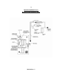
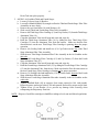
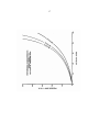
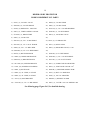
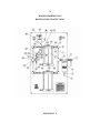
SERVICE MANUAL
TWIN MODEL RP050BMST-S1/2
RESPIRATORY PROTECTOR®
*********************************************************************************
WARNING: Do not attempt to operate this equipment without first reading and
understanding these operating instructions. Suitability for use of this device lies solely with
user.
*********************************************************************************
10/01
2
CONTENTS
SPECIFICATIONS . . . . . . . . . . . . . . . . . . . . . . . . . . . . .. . . . . . . . . . . . . . . . . . . . . . . . . . . .
3
GENERAL SAFETY WARNINGS . . . . . . . . . . . . . . . . . . . . . . . . . . . . . . . . . . . . . . . . . . . . . . 4
GENERAL PURIFICATION SYSTEM DESCRIPTION . . . . . . . . . . . . . . . . . . . . . . . . . . . .
5
GENERAL OPERATIONS
INTRODUCTION . . . . . . . . . . . . . . . . . . . . . . . . . . . . . . . . . . . . . . . . . . . . . . . . . . . .
8
CUSTOMER AIR SUPPLY . . . . . . . . . . . . . . . . . . . . . . . . . . . . . . . . . . . . . . . . . . . . . . 8
MST RESPIRATORY PROTECTOR
INITIAL INSTALLATION AND START - UP . . . . . . . . . . . . . . . . . . . . . . . . . . . . ..
9
MST RESPIRATORY PROTECTOR
GENERAL OPERATION AND MAINTENANCE . . . . . . . . . . . . . . . . . . . . . . . . . . . . 11
FILTER SET SERVICE INSTRUCTIONS . . . . . . . . . . . . . . . . . . . . . . . . . . . . . . . . . . 12
RECORD KEEPING . . . . . . . . . . . . . . . . . . . . . . . . . . . . . . . . . . . . . . . . . . . . . . . . . . . . . . . .
15
PERFORMANCE CURVES . . . . . . . . . . . . . . . . . . . . . . . . . . . . . . . . . . . . . . . . . . . . . . . . . .
17
PART LIST . . . . . . . . . . . . . . . . . . . . . . . . . . . . . . . . . . . . . . . . . . . . . . . . . . . . . . . . . . . . . . .. 19
MATERIAL SAFETY DATA SHEETS
CHARCOAL (THIRD STAGE) . . . . . . . . . . . . . . . . . . . . . . . . . . . . . . . . . . . . . . . . . . 25
CATALYST (FOURTH STAGE). . . . . . . . . . . . . . . . . . . . . . . . . . . . . . . . . . . . . . . . .
21
3
SPECIFICATIONS
RESPIRATORY PROTECTOR
RP050BMST-S1/2
INLET PRESSURE (Max.)
150 PSIG STATIC (10.4 bar)
RATED AIR FLOW (Max.)
100 SCFM (47.2 L/s)
OPERATING PRESSURE
100 PSIG DYNAMIC (6.9 bar)
OUTLET PRESSURE RANGE
0-125 PSIG (0-8.6 bar)
OPERATING TEMP. RANGE
68 -150 F (20-65 C) COMPRESSED AIR TEMP
0 - 105 F (-17 TO 40 C) AMBIENT AIR TEMP
OPERATING RELATIVE
HUMIDITY (INLET AIR)
30-100% RH
OUTSIDE DIMENSIONS
48"L x 24"W x 5.75"D
(1219mm x 610mm x 146mm)
WEIGHT (INCLUDING MONITOR)
53 LBS (24.1 kg.)
REPLACEMENT FILTER SET
FX050/2
4
GENERAL SAFETY WARNINGS
WARNING: THE MST RESPIRATORY PROTECTOR® MODELS:
1)
SHOULD NOT be used when the air entering the filtering system is oxygen deficient. The
MST Respiratory Protector® will not increase the oxygen content of the air.
2)
SHOULD NOT be used in Immediately Dangerous to Life and Health Atmosphere (IDLH)
unless it is used in conjunction with a Back-Up Escape system or a supplied air SelfContained Breathing Apparatus (SCBA), where applicable.
3)
CARBON MONOXIDE MONITOR will alarm if Carbon Monoxide levels exceed
requirements for Grade “D” Breathing Air set fourth by OSHA/CSA. If alarm should sound,
remove respirator or activate SCBA and immediately move to safe breathable atmosphere.
Have the proper qualified personnel examine the equipment and make the appropriate
corrections before using again.
4)
SHOULD NOT have air inlet pressure greater than 150 PSIG static (10.4 bar). Personal
injury could result.
5)
PURIFIED AIR provided at the point - of - attachment for the Manufactures’
Respirator/Hose should be regulated and not exceeding the Manufacturers’ Respirator/Hose
Assembly pressure requirements.
5
GENERAL PURIFICATION SYSTEM DESCRIPTION
The MST Respiratory Protector, a compressed breathing air purifier, is a system designed to remove
or reduce selected contaminates, including Carbon Monoxide that is found in standard compressed
air lines. The Respiratory Protector gives you the advantage of connecting directly to shop air from
a standard compressed air source to help provide breathing quality air to face masks, helmets, hoods
and other supplied air breathing devices. This eliminates the necessity of providing a separate
breathing air compressor or air supply to your workers.
The Respiratory Protector has a four stage filtration system and a Carbon Monoxide Monitor that
is mounted on a convenient mounting board that allows the unit to be mounted on any available
surface.
SYSTEM DESCRIPTION
(Refer to Figure No. 1 & 2)
Air entering the Respiratory Protector Filtration System at the inlet (A) is usually contaminated with
oil, water, dirt, rust, scale and often deadly Carbon Monoxide gas. As the air passes through the First
Stage (B) of the MST Prefilter, particulate matter is trapped and retained. The air then enters the
Second Stage (C) of the Prefilter which coalesces liquid contaminates down to seventy-five
hundredths (0.75) of a micron in size (0.3 micron for particulate matter) with an efficiency rating of
99.97% (meets Underwriters Laboratories Specification UL 586 for High Efficiency, Particulate, Air
Filter Units). The liquid contaminates are trapped in the lower chamber of the prefilter, and expelled
out of the unit by the Auto Drain. The air entering the Air Scrubber Inlets is 99.97% free of liquid
water and contaminants (down to 0.3 micron in size). The Third Stage (D) of the Air Scrubber
contains an odor absorbing activated charcoal which also collects various gaseous Hydrocarbons
(such as oil fumes, benzene, etc). The Fourth Stage (E) of the Air Scrubber contains a low
temperature catalyst which converts Carbon Monoxide gas into Carbon Dioxide. The unique catalyst
also converts or absorbs Ozone, Nitric Oxide, Sulfur Dioxide, Nitrogen Dioxide, Hydrogen Sulfide,
Ammonia, Acetaldehyde, Methyl Chloride, Methyl Ethyl Ketone, Acetone, and Methyl Alcohol.
Finally, the air passes through a one (1) micron Filtration Disk at (F). A sample of the filtered air is
taken at (G) and passed through the Carbon Monoxide Monitor. The Carbon Monoxide Monitor
continuously checks the air quality, per OSHA/CSA requirements for Carbon Monoxide, and digitally
displays the amount present. An audible alarm will alert operators if any dangerous levels of Carbon
Monoxide exist.
6
MODEL RP050BMST-S1/2
OPERATIONAL DIAGRAM
FIGURE NO. 1
7
MODEL RP050BMST-S1/2
RESPIRATORY PROTECTOR
FIGURE NO. 2
8
GENERAL OPERATIONS
******************************************************************************
WARNING: The MST Respiratory Protector should not:
1) be used when the air entering MST's Unit is oxygen deficient. MST's Unit will not increase
the oxygen content of the oxygen deficient air.
2) be used in an "Immediately Dangerous to Life and Health" atmosphere, (IDLH), unless it
is used in conjunction with a back-up escape system or a supplied air self-contained breathing
apparatus, (SCBA), where applicable.
******************************************************************************
MST, Inc. strongly recommends that a complete safety program be instated to ensure that the
respiratory air is in compliance with all OSHA/CSA standards and other applicable laws regulating
the use of supplied air respiratory systems. MST, Inc. recommends that the air quality be tested upon
installation and periodically re-tested to ensure that the minimum requirements for breathing air are
maintained.
MST, Inc. will not assume any liability for accidents or personal injury resulting from the improper
use of this equipment. Service on this equipment should only be performed by qualified personnel.
This system is to be used only by trained qualified personnel in accordance with a respiratory program
as outlined in OSHA Regulation 29 CFR 1910.134(b).
CUSTOMER AIR SUPPLY
(Refer To Figure No. 3)
1) SUPPLIED AIR LINE - Use minimum 3/4" I.D. hose or pipe to MST Unit.
2) SUPPLIED AIR LINE PRESSURE - Maximum air pressure at MST Unit's inlet should not
exceed 150 PSIG. As a Safety Back-Up, all MST Units incorporate a pressure relief valve
rated at 150 PSIG.
3) SUPPLIED INLET AIR TEMPERATURE RANGE - 68 to 150oF (20-65oC).
4) SUPPLIED AIR CONDITIONING - May be required ahead of MST's Unit to control:
a) Inlet air temperature.
b) Large Volumes of oil/water from entering MST Unit. A coarse oil/water extractor,
(rated at 2-microns abs.), may be required if excessive oil/water conditions are present.
Installation of the extractor should be located as close to MST Unit's inlet hook-up
as possible. MST, Inc. has coarse oil/water extractors available as an option.
5) AVOID INSTALLING MST UNIT AFTER DESICCANT DRYER - The Desiccant Dryer
will produce extremely dry air, (4% R.H. or less), and MST's fourth stage catalyst requires
30-100% R.H. in the supplied air for the catalyst to work and remove Carbon Monoxide
efficiently. The extremely dry air produced by a Desiccant Dryer will also cause worker
discomfort, i.e. dry throat, etc.
9
1)
2)
3)
4)
5)
6)
7)
8)
9)
MST RESPIRATORY PROTECTOR INITIAL
INSTALLATION AND START-UP
(Refer To Figure No. 3)
CONNECT CUSTOMER’S PIPE/HOSE TO MST UNIT - Be sure a minimum 3/4" I.D. pipe
or hose is used. Purge new air line prior to connecting to MST Unit.
NEW FILTER SYSTEM CONDITIONING - Flow supplied air through new filter sets for
several minutes to condition.
REMOTE AUDIBLE ALARM - Is supplied with unit. Plug into left side of monitor at the
“REMOTE ALARM” jack. It is supplied with a 20 Ft. cord and produces 119 db. The monitor
itself has a 85 db built-in audible alarm as well as a visual “RED LED” light that will be energized
(along with the Remote Alarm) when the 10 ppm ‘CO’ level (lower in Canada) has been reached.
POWER MONITOR/CALIBRATE - Supply a dedicated 120 VAC switched outlet for the 120
VAC Adapter that comes with unit (adapter will convert the 120 VAC to a 9 VDC output). See
MST MONITOR MANUAL, Accessories section, for further details. Plug the 120 VAC Adapter
cord into the right side of monitor at jack located below the monitor’s battery compartments.
Two 9-volt batteries are supplied with unit and can be installed in monitor to provide a back-up
power source if the main 120 VAC power source fails or is shut-off by mistake. The batteries will
power monitor continually for 30 - 35 hours. After connecting monitor to power source, turn on
and leave warm-up for (5) minutes. Now check monitor’s circuits/audible-visual alarm system
by pressing “OFF/ON TEST” switch up and hold. If monitor OK, the following will occur:
A) Red/Amber LED - will come on steady
B) Green LED - will blink, then come on steady
C) Audible alarm will sound and the remote alarm jack will be energized.
Monitor’s calibration should be checked now. Refer to MST MONITOR MANUAL.
CALIBRATION GAS REQUIREMENTS - Zero Gas: Nitrogen, free of ‘CO’. Span Gas: 50 to
150 ppm of ‘CO’ concentration in air. Calibration gas flow to monitor should be 0.5 to 1.5 SCFH
(approx. 472 cc/min).
REGULATOR/SAMPLE AIR FLOW METER - Needs to be set so proper air sample flow will
be metered to the monitor. The regulator needs to be adjusted up to a maximum 100 PSIG and
the air flow meter ball set between 0.5 - 1.5 SCFH or in the green boxed area, (depending on
style of scale meter has).
EXTREME TEMPERATURE CHANGES - Avoid; MST’s monitor best performs at a
temperature range of 0 - 1050F (-17 to 400C). Always calibrate monitor after it has stabilized in
the surrounding air temperature where system is to be used.
RESPIRATOR/HOOD/HOSE ASSEMBLY HOOK-UP - Consult Manufacturer’s respirator
manual for the proper air pressure requirements and set regulator(s) at point of attachment (MST
Unit outlet or remote regulated drops). The air should be dynamically flowing through
respirator/hose assemblies when the air pressure is set. DO NOT EXCEED
RESPIRATOR/HOSE ASSEMBLY MANUFACTURER’S PRESSURE REQUIREMENTS
OR PERSONAL INJURY COULD RESULT.
‘RF’ SIGNALS - May be picked up by the Remote Alarm cord (like an antenna) and create
interference with monitor’s operation. Shielding of this may be required to reflect these signals.
For further detail contact factory.
10
MODEL RP050BMST-S1/2
RESPIRATORY PROTECTOR®
FIGURE NO. 3
11
MST RESPIRATORY PROTECTOR®
GENERAL OPERATION AND MAINTENANCE
1) MST MONITOR - Utilizes an electrochemical sensor to measure the carbon monoxide
content of the respirable air. If a problem has developed in the system, the monitor will
alarm due to one or more of the following conditions:
a) Monitor is out of calibration. The monitor should be calibrated monthly if used
continuously and prior to use if used on a non-continuous basis. Calibrate monitor
as outlined in the MST MONITOR MANUAL.
b) If the monitor can be and is calibrated, but the alarm still sounds, the filter cartridge
life is exhausted. Replace all three (3) filter cartridges as outlined in the FILTER
REPLACEMENT INSTRUCTIONS, page 12.
c) If the monitor can not be calibrated, the carbon monoxide sensor may require
replacement. See MST MONITOR MANUAL for replacement instructions and other
troubleshooting information. The MST MONITOR has one (1) year warranty. All
warranty work must be performed at factory.
d) If the monitor was calibrated in a surrounding temperature other than where the
system was being used and the temperature difference was 36oF (20oC) or greater, the
monitor may give a false alarm due to its characteristics. Always calibrate the
monitor in the temperature conditions where the monitor is to be used in. Monitor
best performs at temperature range of 0 to 105oF (-17 to 40oC).
e) ‘RF’ signals causing interference to monitor through Remote Alarm Options and/or
Optional Power Adapter cords. Contact factory if this is occurring.
2) MST MONITOR - Alarms should be checked prior to use.
3) MST MONITOR - Power supply is (2) 9-volt transistor - type batteries, (unless optional
power supply used). The batteries will power the monitor continuously for approximately
(30-35) hours. When the batteries output fall below (7.3) volts, the Amber LED "Low
Battery" light will come on, indicating the batteries require replacement. When installing the
new batteries into the battery holders, review polarity position marked inside holders and
install batteries accordingly.
4) MST MONITOR - Flow of the air sample to monitor should be checked periodically to ensure
sample air flow meter is not clogged. This situation normally occurs when customers' supplied
air has excessive liquids in it and the filters in the MST unit are not routinely c h a n g e d .
Periodically check the regulator/air flow meter for proper setting/location of air flow meter
floating ball and general appearance (presence of excessive oil, water).
5) MST RESPIRATORY PROTECTOR® SYSTEM - Filters should be replaced monthly unless
the air quality conditions warrant more or less frequent replacement. Replace all (5) filter
cartridges if:
a) The "CO" monitor alarms (fourth stage catalyst is used up).
b) The operator detects a petroleum smell and or taste in his purified air (third stage
charcoal is used up).
NOTE: If the supplied air entering MST's unit has high volumes of liquids in it, the filter set life may
be greatly reduced. See CUSTOMER AIR SUPPLY, page 8, for corrective
measures to take.
6) MST RESPIRATORY PROTECTOR® SYSTEM - New filter set:
a) Has no shelf life, but should be stored in a cool/dry storage area.
12
b) When first installed in MST's unit the filters should be conditioned by flowing the
customer's supplied air through system for several minutes.
NOTE: If MST's unit is not to be used for an extended period of time, before storing, check
3rd and 4th stage filters for presence of liquid/moisture. If moisture present, dry system and
replace all filters. Also, if moisture present, consider changing filter set more frequent and
or installing MST's OPTIONAL PREFILTER prior to MST's system hook-up.
FILTER SET
SERVICE INSTRUCTIONS
(Refer To Figure No. 4)
*********************************************************************************
WARNING: Always turn off air supply and bleed air pressure before disassembling unit or
serious injury could result.
*********************************************************************************
MST, Inc. recommends replacing all five (5) filter cartridges after one month’s use, unless conditions
warrant more or less frequent replacement. Conditioning equipment prior to the filtration system will
increase the required service intervals when only low levels (below 25 ppm CO) of carbon monoxide
are present.
To refill or replace the filter cartridges in the respiratory Protector Model RP050BMST-S1/2, follow
these steps (refer to Figure No. 4):
1. 8009001 Prefilter-Combined First and Second Stages
a. Remove plastic Drain Tube (1) by pulling down on the Retaining Collar of Fitting (2) to
release Drain Tube.
b. Unscrew Prefilter Bowl Assembly (3) from Manifold (5) and clean Bowl Assembly in
mild soap and water, blowing dry with low pressure compressed air.
c. Remove Two-Stage Prefilter Element (6) by unscrewing End Cap Retaining Nut (4) and
pulling Prefilter Element down over center rod of Manifold.
d. Discard clogged Prefilter Element.
e. Inspect Manifold (5) for dirt and contaminates, clean as required, and inspect O-Ring
(7) located inside Manifold for any cuts or cracks. Replace O-Ring, if required, to
prevent air leakage.
f. Install new Two-Stage Prefilter Element (6) by sliding new Element over center rod on
Manifold so that rod protrudes from end of Element and Element is squarely seated
against Manifold with rod centered in Element.
g. Screw End Cap Retaining Nut (4) onto threaded portion of rod until End Cap Retaining
Nut is seated properly against end of Prefilter Element and Element has come solidly
against shoulder in Manifold.
h. Apply a light film of petroleum jelly on beveled edge of Prefilter Bowl Assembly (3) and
screw bowl Assembly into Manifold (5) until tight (NOTE: Be sure O-Ring is properly
seated in Manifold to prevent cutting O-Ring).
HAND TIGHTEN ONLY!
i. Re-attach Drain Tube (1) by sliding Drain Tube into end of Fitting (2) and pushing
Retaining collar up to lock Drain Tube in place. Be sure to slide outside diameter of
Drain Tube completely into inside diameter of Fitting or Retaining collar will not lock
13
Drain Tube into place properly.
2. 8007803 Air Scrubber-Third and Fourth Stages
a. Loosen (8) Screw from (9) Bracket.
b. Loosen five Manifold Bolts(10) enough to allow the Third and Fourth Stage Filter Tube
Assemblies to move freely.
c. Remove the two front Bolts (10) with Washers (11).
d. Slide out old Third And Fourth Stage Filter Tube Assemblies.
e. Remove old Third Stage Filter Cartridge (13) and Cap Gasket (12) from the Third Stage
Aluminum Tube (16) .
f. Clean the Aluminum Tube in mild soap and water and wipe dry.
g. Refill the Third Stage Aluminum Tube (16) by sliding the new Third Stage Filter
Cartridge (13) into the Aluminum Tube from the bottom.. Make sure that the flow
direction arrow on the new Third Stage Filter Cartridge is pointing down for proper
operation.
h. Remove (14) Sealing Label and install new (12) Cap Gasket on the top of the Third
Stage Aluminum Filter Tube Assembly.
i. Slide the new Third Stage Aluminum Filter Tube Assembly in the Air Scrubber on the
inlet side.
j. Remove old Fourth Stage Filter Cartridge (15) and Cap Gasket (12) from the Fourth
Stage Aluminum Tube (17).
k. Clean the Aluminum Tube in mild soap and water and wipe dry.
l. Refill the Fourth Stage Aluminum Tube (17) by sliding the Fourth Stage Filter Cartridge
(15) into the Aluminum Tube from the top. Make sure that the flow direction arrow on
the new Fourth Stage Filter Cartridge is pointing up for proper operation.
m. Remove (14) Sealing Label and install new (12) Cap Gasket on the bottom of the Fourth
Stage Aluminum filter tube Assembly.
n. Slide the new Fourth Stage Aluminum filter tube Assembly in the Air Scrubber on the
outlet side.
o. Tighten Manifold Bolts (10) in sequence from center outward to 100 inch-pounds.
Repeat Sequence and torque bolts to 250 inch-pounds. Recheck for proper torque limit.
p. Tighten Screw (8) on Bracket (9) to prevent any damage from occurring when
transporting the Respiratory Protector.
NOTE: Dispose of used filter cartridges in landfill according to local, state and federal regulations.
14
FIGURE NO. 4
15
3. Final Check and Calibration:
a. Pressurize system and check for leaks. Re-tighten necessary parts to stop any
leakage.
b. Flush system with compressed air for five (5) minutes.
c. Calibrate the Carbon Monoxide Monitor as outlined in the Monitor’s
instruction manual.
RECORD KEEPING:
Record all periodical air quality checks, monitor calibration dates, filter cartridge change intervals and
any other service performed on the Model RP050BMST-S1/2
Respiratory Protector.
MST, Inc. Shall not be liable for any injury, loss, or damage, direct or consequential, arising
out of the use of or the inability to use this product, beyond the replacement of defective
materials or workmanship. Users of supplied air respirators should evaluate their own
particular application and perform their own tests for air quality to determine the suitability
for use of this product.
For further information, or questions about service or maintenance care of this unit, contact your local
distributor or MST, Inc. At (800) 542-6646.
16
MST, INC.
SERVICE RECORD
RESPIRATORY PROTECTOR
MODEL RP050BMST-S1/2
DATE OF SERVICE
SERVICE PERFORMED
17
18
19
RESPIRATORY PROTECTOR
MODEL RP050BMST-S1/2 PARTS
1) 80347, (1), 3/4" BALL VALVE
21) 80484, (2), 3/8" BR. UNION
2) S608-009, (2), 3/4" HEX NIPPLE
22) 80483, (1), 3/4" BR. CROSS
3) 80104, (1), PREFILTER - 100 SCFM
23) S638-016, (1), 3/4" x 1/4" RED BUSHING
4) 80051, (5), TUBE LOCKING COLLAR
24) S608-003, (1), 1/4" HEX NIPPLE
5) S710-005, (1), DRAIN TUBE
25) 80014, (1), 150 PSI PR. VALVE
6) 80067, (1), 3/4" BR. TEE
26)
7) S603-038, (4), 3/4" x 8" BR. NIPPLE
27) 80235, (1), 1/4" BRASS TEE
8) S623-005, (4), 3/4" x 90 ST. ELBOW
28) 80533, (1), REGULATOR
9) 80068, (4), 3/4" x 1/2" BELL RED.
29) 80091, (1), PRESSURE GAUGE, 0 - 160
10) S608-006, (4), 3/8" x 1/2" HEX NIPPLE
30)
11) 80078, (2), BLUE MANIFOLD
31) S608-003, (1) 1/4" HEX NIPPLE
12) 80009, (2), MANIFOLD BRACKET
32) S608-002, (1), 1/4" x 1/8" HEX NIPPLE
13) S006-148, (6), BRACKET BOLTS
33) S623-001, (1), 1/8" 900 ST. ELBOW
14) S011-040, (10), MANIFOLD BOLTS
34) 80213, (1), SAMPLE AIR FLOW METER
15) 12021, (10), MANIFOLD WASHERS
35) 80261, (1), TUBE LOCK COLLAR x 900
16) 80001, (2), BLUE BASE
36) 80208-B, (1), MONITOR SAMPLE TUBE
17) 80005, (2), AL. TUBE, 3RD STAGE
37) 80127, (1), MST ‘CO’ MONITOR
18) 80005, (2), AL. TUBE, 4TH STAGE
38) 80247, (1), 120 VAC ADAPTER
19)
80114, (2), BASE BRACKET
39) 8008403, (1), REMOTE ALARM
20)
S603-025, (2), 3/8" x 2" BR. NIPPLE
40) 80257, (1), 1/2' THK x 24" x 48" MNTING. BD.
See following page, Figure No.5, for detailed drawing.
20
MODEL RP050BMST-S1/2
RESPIRATORY PROTECTOR®
FIGURE NO. 5