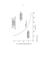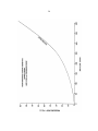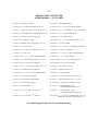
1
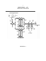
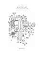
SERVICE MANUAL
TWIN MODEL RP200C( _ )-S1/2
RESPIRATORY PROTECTOR®
*********************************************************************************
WARNING: Do not attempt to operate this equipment without first reading and unde rstanding
these operating instructions. Suitability for use of this device lies solely with user.
*********************************************************************************
2/05
2
CONTEN TS
SPECIFICATIONS . . . . . . . . . . . . . . . . . . . . . . . . . . . . .. . . . . . . . . . . . . . . . . . . . . . . . . . . . . .
3
GENERAL SAFETY WARNINGS . . . . . . . . . . . . . . . . . . . . . . . . . . . . . . . . . . . . . . . . . . . . . .
4
GENERAL PURIFICATION SYSTEM DESCRIPTION . . . . . . . . . . . . . . . . . . . . . . . . . . . . .
5
GENERAL OPERATIONS
INTRODUCTION . . . . . . . . . . . . . . . . . . . . . . . . . . . . . . . . . . . . . . . . . . . . . . . . . . . . .
8
CUSTOMER AIR SUPPLY . . . . . . . . . . . . . . . . . . . . . . . . . . . . . . . . . . . . . . . . . . . . . .
8
MST RESPIRATORY PROTECTOR
INITIAL INSTALLATION AND START - UP . . . . . . . . . . . . . . . . . . . . . . . . . . . . . .
9
MST RESPIRATORY PROTECTOR
GENERAL OPERATION AND MAINTENANCE . . . . . . . . . . . . . . . . . . . . . . . . . . . . 12
ESTIMATED MAINTENANCE REQUIREMENTS. . . . . . . . . . . . . . . . . . . . . . . . . . . . . . . . . 13
FILTER SET SERVICE INSTRUCTIONS . . . . . . . . . . . . . . . . . . . . . . . . . . . . . . . . . . 14
RECORD KEEPING . . . . . . . . . . . . . . . . . . . . . . . . . . . . . . . . . . . . . . . . . . . . . . . . . . . . . . . . .
17
PERFORMANCE CURVES . . . . . . . . . . . . . . . . . . . . . . . . . . . . . . . . . . . . . . . . . . . . . . . . . . .
19,20
PART LIST . . . . . . . . . . . . . . . . . . . . . . . . . . . . . . . . . . . . . . . . . . . . . . . . . . . . . . . . . . . . . . . .
21,22
3
SPECIFICATIONS
RESPIRATORY PROTECTOR
RP200C( _ )-S1/2
INLET PRESSURE (Max.)
150 PSIG STATIC (10.4 bar)
RATED AIR FLOW (Max.)
250 SCFM (118.0 L/s)
OPERATING PRESSURE
100 PSIG DYNAMIC (6.9 bar)
OUTLET PRESSURE RANGE
0-125 PSIG (0-8.6 bar)
OPERATING TEMP. RANGE
68 -150 F (20-65 C) COMPRESSED AIR TEMP
0 - 105 F (-17 TO 40 C) AMBIENT AIR TEMP
OPERATING RELATIVE
HUMIDITY (INLET AIR)
30- 90% RH
OUTSIDE DIMENSIONS
66"L x 36"W x 7.75"D
(1676mm x 714mm x 197mm)
WEIGHT (INCLUDING MONITOR)
250 LBS (113.7 kg.)
REPLACEMENT FILTERS
-GRADE 10 ELEMEN T FOR 80411 PRE-COALESCER FILTER
-GRADE 6 ELEMENT FOR 80412 PREFILTER
-THIRD STAGE CHARCOAL CARTRIDGE W/GASKETS
(2 REQ’D PER UNIT)
-FOURTH STAGE CATALYST CARTRIDGE W/ GASKETS
(2 REQ’D PER UNIT)
80403
80404
80174-203
80174-204
4
GENERAL SAFETY WARNINGS
WARNING: THE MST RESPIRATORY PROTECTOR® MODELS:
1)
SHOULD NOT be used when the air entering the filtering system is oxygen deficient. The
MST Respiratory Protector® will not increase the oxygen content of the air.
2)
SHOULD NOT be used in Immediately Dangerous to Life and Health Atmosphere (IDLH)
unless it is used in conjunction with a Back-Up Escape system or a supplied air SelfContained Breathing Apparatus (SCBA), where applicable.
3)
CARBON MONOXIDE MONITOR will alarm if Carbon Monoxide levels exceed
requirements for Grade “D” Breathing Air set fourth by OSHA/CSA. If alarm should sound,
remove respirator or activate SCBA and immediately move to safe breathable atmosphere.
Have the proper qualified personnel examine the equipment and make the appropriate
corrections before using again.
4)
SHOULD NOT have air inlet pressure greater than 150 PSIG static (10.4 bar). Personal
injury could result.
5)
PURIFIED AIR provided at the point - of - attachment for the Manufactures’
Respirator/Hose should be regulated and not exceeding the Manufacturers’ Respirator/Hose
Assembly pressure requirements.
5
GENERAL PURIFICATION SYSTEM DESCRIPTION
The MST Respiratory Protector, a compressed breathing air purifier, is a system designed to remove
or reduce selected contaminates, including Carbon Monoxide that is found in standard compressed
air lines. The Respiratory Protector gives you the advantage of connecting directly to shop air from
a standard compressed air source to help provide breathing quality air to face masks, helmets, hoods
and other supplied air breathing devices. This eliminates the necessity of providing a separate
breathing air compressor or air supply to your workers.
The Respiratory Protector has a five stage filtration system and a Carbon Monoxide Monitor that is
mounted on a convenient mounting board that allows the unit to be mounted on any available
surface.
SYSTEM DESCRIPTION
(Refer to Figure No. 1 & 2)
Air entering the Respiratory Protector Filtration System at the inlet (A) is usually contaminated with
oil, water, dirt, rust, scale and often deadly Carbon Monoxide gas. As the air passes through the Precoalescer Stage (B), particulate and liquid contaminates will be trapped and coalesced out, (greater
than 0.7 micron solids trapped and down to 2.0 micron liquid aerosols removed at an efficiency
rating of 95%). The liquids are trapped and expelled throught the Automatic Float Drain. The
Differential Pressure Gauge (DPG) at (C), will indicate when the element requires changing. The
First Stage (D) of Prefilter, traps and retains particulate matter 3.0 micron and larger by a high
surface area pleated filter media. The air then passes through the Second Stage (E) of Prefilter, which
traps all particulate matter larger then 0.3 micron and coalesces liquid aerosols with an efficiency
rating of 99.97%, (this meets Underwriter Laboratory Specifications UL586 for high efficiency,
particulate, air filter units (HEPA Rating). The liquids are trapped and expelled through the
Automatic Float Drain. The “DPG” at (F), will indicate when the element requires changing. The
Third Stage (G), contains a deep bed of odor absorbing activated charcoal which collects various
gaseous Hydrocarbons (such as oil vapors, benzene, etc.), and removes them. The Fourth Stage (H),
contains a low termperature catalyst which converts Carbon Monoxide gas into Carbon Dioxide. The
unique catalyst also converts or absorbs Ozone, Nitric Oxide,Sulfur Dioxide, Nitrogen Dioxide,
Hydrogen Sulfide, Ammonia, Acetaldehyde, Methyl Chloride, MethylEthyl Ketone, Acetone and
Methyl Alcohol. Finally, the air passes through a one (1) micron filter disc at (I). A sample of the
filtered air is taken at (J) and passed through the Carbon Monoxide Monitor. The monitor
continuously checks the air quality, per OSHA/CSA requirements for Carbon Monoxide and
digitally displays the amount present in PPM, (parts per million). An audible alarm will alert
operators if levels of Carbon Monoxide exceed OSHA/CSA requirements.
6
MODEL RP200C( _ )-S1/2
OPERATIONAL DIAGRAM
FIGURE NO. 1
7
MODEL RP200C( _ )-S1/2
RESPIRATORY PROTECTOR
8
GENERAL OPERATIONS
******************************************************************************
WARNING: The MST Respiratory Protector should not:
1) be used when the air entering MST's Unit is oxygen deficient. MST's Unit will not increase
the oxygen content of the oxygen deficient air.
2) be used in an "Immediately Dangerous to Life and Health" atmosphere, (IDLH), unless it
is used in conjunction with a back-up escape system or a supplied air self-contained breathing
apparatus, (SCBA), where applicable.
******************************************************************************
MST, Inc. strongly recommends that a complete safety program be instated to ensure that the
respiratory air is in compliance with all OSHA/CSA standards and other applicable laws regulating
the use of supplied air respiratory systems. MST, Inc. recommends that the air quality be tested
upon installation and periodically re-tested to ensure that the minimum requirements for breathing
air are maintained.
MST, Inc. will not assume any liability for accidents or personal injury resulting from the improper
use of this equipment. Service on this equipment should only be performed by qualified personnel.
This system is to be used only by trained qualified personnel in accordance with a respiratory
program as outlined in OSHA Regulation 29 CFR 1910.134(b).
CUSTOMER AIR SUPPLY
(Refer To Figure No. 3)
1) SUPPLIED AIR LINE - Use minimum 2" I.D. hose or pipe to MST Unit.
2) SUPPLIED AIR LINE PRESSURE - Maximum air pressure at MST Unit's inlet should not
exceed 150 PSIG. As a Safety Back-Up, all MST Units incorporate a pressure relief valve
rated at 150 PSIG.
3) SUPPLIED INLET AIR TEMPERATURE RANGE - 68 to 150oF (20-65oC).
4) SUPPLIED AIR CONDITIONING - May be required ahead of MST's Unit to control inlet air
temperature.
5) AVOID INSTALLING MST UNIT AFTER DESICCANT DRYER - The Desiccant Dryer
will produce extremely dry air, (4% R.H. or less), and MST's fourth stage catalyst requires
30-90% R.H. in the supplied air for the catalyst to work and remove Carbon Monoxide
efficiently. The extremely dry air produced by a Desiccant Dryer will also cause worker
discomfort, i.e. dry throat, etc.
9
MST RESPIRATORY PROTECTOR INITIAL
INSTALLATION AND START-UP
(Refer To Figure No. 3)
1) CONNECT CUSTOMER’S PIPE/HOSE TO MST UNIT - Be sure a minimum 2" I.D. pipe or
hose is used. Purge new air line prior to connecting to MST Unit. Be sure all solvent fumes and
gross particulates (that could build up when initially assembling inlet piping) are purged out of
line (s). This will prevent overloading of MST Unit’s filter elements.
2) NEW FILTER SYSTEM CONDITIONING - Flow supplied air through new filter sets for
several minutes to condition.
3) REMOTE AUDIBLE ALARM - Is supplied with unit. Plug into the bottom of monitor. It is
supplied with a 20 Ft. cord and produces 119db. Check Audible Alarm by rotating “zero
potentiometer” (CW) unitl display reading is equal to alarm level setting (US=10 ppm, CAN=5
ppm). The audible alarm should be energized. The “zero pontentiometer” will have to be reset
to ‘00' using “zero air” calibration gas, (refer to Monitor manual).
4) POWER MONITOR/CALIBRATE -Connect the Power Cord or Adapter to a dedicated 110
VAC switched outlet power source. Be sure the monitor’s “Normal or Power” light is on, and
after a (5) minute warm-up, calibrate monitor. Refer to Carbon Monoxide Monitor Manual.
5) CALIBRATION GAS REQUIREMENTS - Zero Gas: Nitrogen, free of ‘CO’. Span Gas: 50 to
150 ppm of ‘CO’ concentration in air. Calibration gas flow to monitor should be 0.5 to 1.5
SCFH (approx. 472 cc/min).
6) REGULATOR/SAMPLE AIR FLOW METER -After pressurizing system and respirators air
flow set, adjust regulator located before air sample flowmeter to 10-20 psi pressure. Turn the
flowmeter’s adjustment knob counter-clockwise slowly until the black floating ball is within the
GREEN BOX area etched on the flowmeter’s body. CAUTION: if adjustment knob is turned
too quickly, the black floating ball may get stuck to the top of the flowmeter scale. Damage to
monitor’s sensor may occur due to extremely high air flow to sensor, (not covered by sensor
warranty).
7) EXTREME TEMPERATURE CHANGES - Avoid; monitor best performs at a temperature
range of 32 - 1050F (0 to 400C). Always calibrate monitor after it has stabilized in the
surrounding air temperature where system is to be used.
8) RESPIRATOR/HOOD/HOSE ASSEMBLY HOOK-UP - Consult Manufacturer’s respirator
manual for the proper air pressure requirements and set regulator(s) at point of attachment (MST
Unit outlet or remote regulated drops). The air should be dynamically flowing through
respirator/hose assemblies when the air pressure is set. DO NOT EXCEED
RESPIRATOR/HOSE ASSEMBLY MANUFACTURER’S PRESSURE REQUIREMENTS
OR PERSONAL INJURY COULD RESULT.
10
MODEL RP200C( _ )-S1/2
RESPIRATORY PROTECTOR®
FIGURE NO. 3
11
******************************************************************************
WARNING : SERIOUS INJURY could result if the AIR SAMPLE METERING VALVE is
not properly adjusted. Proper sample air flow to ‘CO’ monitor is required for monitor to give
correct ‘CO’ level readout.
******************************************************************************
AIR SAMPLE METERING VALVE ADJUSTMENT
(REFER TO FIGURE NO. 4)
1) After pressurizing system and respirators air flow is set, adjust the air sample regulator to 10-20
PSI pressure.
2) Turn the flowmeter’s adjustment knob counter-clockwise slowly until the black floating ball is
within the GREEN BOXED AREA etched on flowmeter body. CAUTION: if adjustment knob
is turned too quickly, the black floating ball may get stuck to the top of flowmeter scale. Damage
to monitor’s sensor may occur due to extremely high air flow to sensor, (not covered by sensor
warranty).
Figure no. 4
12
MST RESPIRATORY PROTECTOR®
GENERAL OPERATION AND MAINTENANCE
1) MONITOR - Utilizes an electrochemical sensor to measure the carbon monoxide content of the
respirable air. If a problem has developed in the system, the monitor will alarm due to one or
more of the following conditions:
a)
Monitor may be out of calibration. The monitor should be calibrated monthly if used
continuously and prior to use if used on a non-continuous basis. Calibrate monitor
as outlined in the MONITOR MANUAL.
b)
If the monitor can be and is calibrated, but the alarm still sounds, the filter cartridge
life is exhausted. Replacement of filter elements as outlined in the Filter
Replacement Instructions, page 14 , as required.
c)
If the monitor can not be calibrated, the carbon monoxide sensor may require
replacement. See MONITOR MANUAL for replacement instructions and other
troubleshooting information. The MONITOR has one (1) year warranty (sensor has
a two (2) year warranty). All warranty work must be performed at factory.
d)
If the monitor was calibrated in a surrounding temperature other than where the
system was being used and the temperature difference was 36oF (20oC) or greater, the
monitor may give a false alarm due to its characteristics. Always calibrate the
monitor in the temperature conditions where the monitor is to be used in. Monitor
best performs at temperature range of 32 to 105oF (0 to 40oC).
2) CARBON MONOXIDE MONITOR - Alarm should be checked periodically. Refer to Monitor
Manual.
3) MONITOR - Flow of the air sample to monitor should be checked periodically to ensure
sample air flow meter is not clogged. This situation normally occurs when customers' supplied
air has excessive liquids in it and the filters in the MST unit are not routinely c h a n g e d .
Periodically check the regulator/air flow meter for proper setting/location of air flow meter
floating ball and general appearance (presence of excessive oil, water).
4) MST RESPIRATORY PROTECTOR® SYSTEM - Filters should be replaced every (9) months
unless the air quality conditions warrant more or less frequent replacement. Replace all (6) filter
cartridges if:
a)
The "CO" monitor alarms (fourth stage catalyst is used up).
b)
The operator detects a petroleum smell and or taste in his purified air (third stage
charcoal is used up).
NOTE: If the supplied air entering MST's unit has high volumes of liquids in it, the filter
set life may be greatly reduced.
5) MST RESPIRATORY PROTECTOR® SYSTEM - New filter set:
a)
Shelf life is indefinate, but should be stored in a cool/dry storage area.
b)
When first installed in MST's unit the filters should be conditioned by flowing the
customer's supplied air through system for several minutes.
13
14
FILTER SET
SERVICE INSTRUCTIONS
(Refer To Figure No. 5 and 6)
******************************************************************************
WARNING: Always turn off air supply and bleed air pressure before disassembling unit or
SERIOUS INJURY COULD RESULT.
******************************************************************************
MST, Inc. recommends replacing all (6) filter cartridges after (9) months of use unless
conditions warrant more or less frequent replacement. To replace the filter cartridges in the
RESPIRATORY PROTECTOR® follow these steps:
1) PRE-COALESCER STAGE, GRADE 10, ELEMENT REPLACEMENT
Element change is required when the Differential Pressure Gauge (‘DPG’) indicates a 6 - 10
PSID, 12 PSID max., (Refer to Figure No. 5).
1) First unscrew Bowl Assembly (1). A strap wrench may be required to break bowl, Oring/manifold seal. Clean bowl ass’y in mild soap and water and blow dry with low
pressure air.
2) Remove Coalescing Element (2) by unscrewing End Cap Retaining Nut (3).
3) Inspect the Filter Manifold (4) for dirt/contaminates and clean as required. Inspect O-ring
(5) for cuts etc. and replace if required. Clean and apply light film of
petroleum jell
on O-ring before re-installing.
4) Install new Coalescing Element and tighten End Cap Retaining Nut. Be sure Element is
seated squarely on Manifold’s boss and End Cap.
5) Apply light film of petroleum jell on Bowl’s beveled edge and threads to provide good
seal. HAND TIGHTEN ONLY to Manifold.
6) Dispose of used Coalescing Element according to local, state and federal regulations.
2) THE FIRST/SECOND DUAL STAGE, GRADE 6, ELEMENT REPLACEMENT
The Dual stage element change is required when the Differential Pressure Gauge (‘DPG’)
indicates an 8 -10 PSID, (Refer to Figure No. 5).
1) Replace the Dual Stage Element (6) using the above “Prefilter Stage Element”
replacement instructions.
2) Dispose of used Prefilter Dual Stage Element according to local, state and federal
regulations.
15
FIGURE NO. 5
3) THIRD/FOURTH STAGE CARTRIDGE REPLACEMENT
(Third Stage - Charcoal, Fourth Stage - Catalyst, Refer to Figure No. 6)
a) Loosen Bracket Bolt (1) from Bracket (2), (do not remove), on both sides of Base (3).
b) Loosen the five Manifold Bolts (4) and remove the front two Bolts. Now slide out
the Third (5) and Fourth (6) Stage Aluminum Tube Assemblies.
c) Remove the four old Gaskets (7) from the recessed areas in Base (3) and Manifold
(8); cleaning sealing surfaces from any gasket material, debris.
d) Slide old Third Stage Filter Cartridge (9) out of aluminum tube. Clean aluminum
tube in mild soap and water, dry and install new Third Stage Filter Cartridge. Be sure
the Flow Direction Arrow on Third Stage Filter Cartridge is pointing down. Remove
End Sealing Labels (10) from both ends of cartridge completely.
e) Follow same procedure for the Fourth Stage Filter Cartridge (11) replacement as in
step (d). Be sure the Flow Direction Arrow on Fourth Stage Filter Cartridge is
pointing up. Also remove End Sealing Labels (10) from both ends of cartridge.
f) Before sliding the Third and Fourth Stage Aluminum Tube Assemblies back in place,
install Gaskets (7). Coat both sides of each gasket with petroleum jelly and install in
recessed areas in Base (3) and Manifold (8). After Aluminum Tube Ass’y are
installed, check to make sure the Gaskets (7) are positioned properly top and bottom
- both ass’y.
g) Replace the front two Manifold Bolts (4) and tighten all bolts in sequence from
center outward to 25 foot-pounds. Repeat sequence and torque bolts to 30 footpounds. Recheck for proper torque limit.
h) Tighten Bracket Bolts (1) against Brackets (2), on both sides.
i) Dispose of used cartridges according to local, state and federal regulations.
16
3) FINAL CHECK AND CALIBRATION
a) Pressurize system and check for leaks.
b) Flush system with compressed air for several minutes.
c) Calibrate Carbon Monoxide Monitor as outlined in the MONITOR MANUAL.
FIGURE NO. 6
3. Final Check and Calibration:
a. Pressurize system and check for leaks. Re-tighten necessary parts to stop any
leakage.
b. Flush system with compressed air for five (5) minutes.
c. Calibrate the Carbon Monoxide Monitor as outlined in the Monitor’s
instruction manual.
17
RECORD KEEPING:
Record all periodical air quality checks, monitor calibration dates, filter cartridge change intervals
and any other service performed on the Respiratory Protector Unit.
MST, Inc. Shall not be liable for any injury, loss, or damage, direct or consequential, arising
out of the use of or the inability to use this product, beyond the replacement of defective
materials or workmanship. Users of supplied air respirators should evaluate their own
particular application and perform their own tests for air quality to determine the suitability
for use of this product.
For further information, or questions about service or maintenance care of this unit, contact your
local distributor or MST, Inc. At (800) 542-6646.
18
MST, INC.
SERVICE RECORD
RESPIRATORY PROTECTOR
MODEL RP200C( _ )-S1/2
DATE OF SERVICE
SERVICE PERFORMED
19
20
21
RESPIRATORY PROTECTOR
MODEL RP200C( _ )-S1/2 PARTS
1) 80425, (1), 2" BALL VALVE
23) 80114, (4), BASE BRACKET
2) S603-092, (3), 2" BR. PIPE NIPPLE x 3" LG.
2 4 ) S0 37-05 6 , (4 ), 1/4"-2 0 x 3 /4 " BH SC REW S
3) 80411, (1), PRE-COALESCER, 450 CFM, GR. 10
25) S412-009, (4), 1/4" INTERNAL LOCK WASHER
4) 80422, (2), DIFFERENTIAL PRESSURE GAUGE
26) 80115, (4), 1/4" FENDER WASHER
5) 80051, (2), TUBE LOCKING COLLAR
27) 80447, (2), 1 1/4" BR. UNION
6) S710-005, (2), DRAIN TUBE
28) S603-075, (2), 1 1/4" BR. PIPE NIPPLE x 2" LG
7) 8041 2, (1), PRE FILTE R, 450 C FM, G R 6, 2-stg
29) 80424, (1), 2" BR. CROSS
8) 80448, (1), 2" BR. UNION
30) S638-017, (2), 1 1/4" X 3/4" BR. HEX BUSHING
9) S603-091, (2), 2" BR. PIPE NIPPLE x 2 ½" LG
31) 80427, (1), 3/4" X 150 PSI PRV
10) 80449, (2), 2" BR. TEE
32) S638-016, (1), 3/4" X 1/4" BR. HEX BUSHING
11) S638-019, (6), 2" x 1 1/4" BR. HEX BUSHING
33) S608-003, (1), 1/4" HEX NIPPLE
12) 80586, (4), 1 1/4" BR. PIPE NIPPLE x 12" LG
NO#) S608-002, (1), 1/4" x 1/8" HEX NIPPLE
13) S622-006, (4), 1 1/4" BR 90O ELBOW
NO#) S623-001, (1), 1/8" 90O ELBOW
14) S603-077, (4), 1 1/4" BR. PIPE NIPPLE x 3" LG.
34) 80091, (1), 0-160 PSI GAUGE
15) 80196, (4), MANIFOLD BRACKETS
35) 80533, (1), REGULATOR, 1/4"
1 6 ) S 0 06 - 150, ( 12) , 5/16"-18 x 3/4" HH S CREW S
36) 80213, (1), FLOWMETER
17) 80187, (10), MANIFOLD BOLTS
37) 80261, (1), 90 O TUBE LOCKING COLLAR
18) 80197, (10), MANFOLD WASHERS
38) 80605, (1), MNT BOARD , 3/4" x 36" x 66"
19) 80173, (2), BLUE MANIFOLD
39) 8008403, (1), REMOTE ALA RM, (119db)
20) 80172, (2), BLUE BASE
40) 80077, (1), CO MONITOR - 2002
FOR MO DEL RP200 CA-S1 /2
21) 80176-2, (2), AL. TU BE - 3 RD STAGE
41) 80127, (1), CO MONITOR - 5700
FOR MO DEL RP200 CMS T-S1/2
22) 80176-2, (2), AL. TU BE - 4 TH STAGE
41A) 80247, (1), 110 VAC ADAPTER FOR 5700 CO
MONIT OR, M ODE L RP2 00CM ST-S1 /2
See following page, Figure No.7, for detailed drawing.
22
MODEL RP200C( _ )-S1/2
RESPIRATORY PROTECTOR®
FIGURE NO. 7