1
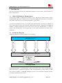
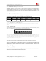
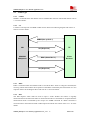
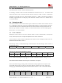
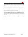
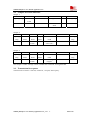
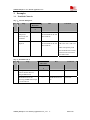
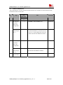
SIM900_Multiplexer
Manual_Application
Note_V1.3
User
SIM900 Multiplexer User Manual Application Note
Document Title:
SIM900 Multiplexer User Manual Application Note
Version:
1.3
Date:
2010-11-17
10Status:
Released
Document Control ID:
SIM900_Multiplexer User Manual_Application Note_V1.3
General Notes
SIMCom offers this information as a service to its customers, to support application and
engineering efforts that use the products designed by SIMCom. The information provided is based
upon requirements specifically provided to SIMCom by the customers. SIMCom has not
undertaken any independent search for additional relevant information, including any information
that may be in the customer’s possession. Furthermore, system validation of this product designed
by SIMCom within a larger electronic system remains the responsibility of the customer or the
customer’s system integrator. All specifications supplied herein are subject to change.
Copyright
This document contains proprietary technical information which is the property of SIMCom
Limited., copying of this document and giving it to others and the using or communication of the
contents thereof, are forbidden without express authority. Offenders are liable to the payment of
damages. All rights reserved in the event of grant of a patent or the registration of a utility model
or design. All specification supplied herein are subject to change without notice at any time.
Copyright © Shanghai SIMCom Wireless Solutions Ltd. 2010
SIM900_Multiplexer User Manual_Application Note_V1.3
2
2010.11.07
SIM900 Multiplexer User Manual Application Note
Content
Version History .................................................................................................................................4
1. Introduction...............................................................................................................................6
1.1. SIMCOM Multiplexer Design Purpose.........................................................................6
1.2. Architecture Diagram....................................................................................................6
1.3. Restrictions....................................................................................................................7
1.4. References.....................................................................................................................7
2. SIMCOM Multiplexer Protocol ................................................................................................8
2.1. Transmission Frame Structures .....................................................................................8
2.1.1.
Opening and Closing Flag Field........................................................................8
2.1.2.
Address Field ....................................................................................................8
2.1.3.
Control Field .....................................................................................................8
2.1.4.
Length Field ......................................................................................................9
2.1.5.
Information Fields.............................................................................................9
2.2. Frame Type..................................................................................................................10
2.2.1.
SABM .............................................................................................................10
2.2.2.
UA...................................................................................................................10
2.2.3.
DISC................................................................................................................10
2.2.4.
DM ..................................................................................................................10
2.2.5.
UIH..................................................................................................................11
2.2.6.
UI ....................................................................................................................11
2.3. DLC Establishment .....................................................................................................12
2.4. Closing Down DLC ....................................................................................................12
2.5. Control channel ...........................................................................................................12
2.5.1.
PSC..................................................................................................................13
2.5.2.
CLD.................................................................................................................13
2.5.3.
Test ..................................................................................................................13
2.5.4.
MSC ................................................................................................................13
2.5.5.
FCoff ...............................................................................................................14
2.5.6.
FCon................................................................................................................14
2.5.7.
PN,NSC,RPN,RLS,SNC .....................................................................14
2.6. Data Channel...............................................................................................................15
2.7. About Flow Control ....................................................................................................16
2.8. Samples for Frame Structure.......................................................................................17
2.9. Transmission bit sequence ..........................................................................................17
3. Examples.................................................................................................................................18
3.1. Establish Channels ......................................................................................................18
3.2. Frame Transmission ....................................................................................................21
3.3. Power Saving Mode and Wake Up..............................................................................22
3.4. Flow Control ...............................................................................................................23
3.5. Dealing with the wrong frame.....................................................................................24
3.6. Closing Down Multiplexers ........................................................................................25
SIM900_Multiplexer User Manual_Application Note_V1.3
3
2010.11.07
SIM900 Multiplexer User Manual Application Note
Version History
Time
Version
Description
Author
2010-1-8
V1.0
Created
WZN
2010-7-9
V1.1
Modified some incorrect response frame
CYH
2010-7-12
V1.2
Review
CYH
2010-11-17
V1.3
Modified frame length flag
WZN
SIM900_Multiplexer User Manual_Application Note_V1.3
4
2010.11.07
SIM900 Multiplexer User Manual Application Note
Abbreviations
DLC:
Data Link Connection
DLCI: Data Link Connection Identifier
RLS:
Remote Line Status Command
SABM: Set Asynchronous Balanced Mode
UA:
Unnumbered Acknowledgement
DM: Disconnected Mode
DISC: Disconnect (DISC) command
UIH: Unnumbered information with header check (UIH) command and response
UI:
Unnumbered Information command and response
PSC:
Power Saving Control
CLD:
Multiplexer Close Down
MSC:
Modem Status Command
TE:
Terminal Equipment
MS:
Mobile Station
FC:
Flow Control
RTC: Ready To Communicate
RTR: Ready To Receive
IC:
Incoming Call Indicator
DV:
Data Valid
PN:
Parameter Negotiation
FCon: Flow Control On Command
FCoff: Flow Control Off Command
NSC: Non Support Command
RPN: Remote Port Negotiation
RLS: Remote Line Status Command
SNC: Service Negotiation Command
TE:
Terminal Equipment
MS:
Mobile Station
SIM900_Multiplexer User Manual_Application Note_V1.3
5
2010.11.07
SIM900 Multiplexer User Manual Application Note
1. Introduction
The present document describes the SIMCOM multiplexer protocol and the technical details of
how to make use of it.
1.1. SIMCOM Multiplexer Design Purpose
A device using GPRS or GSM data may wish to receive and transmit multiple streams of data
simultaneously. These are Command data (AT commands), GPRS data and GSM circuit switched
data (CSD). These streams are essentially independent to one another.
As to the non-multiplexer device, it is so inefficient to deal with only one kind or one channel of
data steam during a period of time. Therefore, SIMCOM multiplexer is designed with GSM0710
standard to separate transmission device layer into several logic channels (DLC) in order to
transmit data simultaneously. Each channel has its own buffer management and flow control
mechanism.
1.2. Architecture Diagram
SIMCOM multiplexer architecture diagram is as following:
SIMCOM Multiplexer
D
L
C
1
D
L
C
2
D
L
C
3
D
L
C
4
Transmission Device Layer (Serial Port)
Multiplexed
data
streams
Client Application
SIMCOM Multiplexer is established upon system transmission device layer (Commonly serial
port). Data streams are addressed with DLCI value and encapsulated in frames based on GSM
0710 protocol (Chapter 2, SIMCOM Multiplexer Protocol) and transmitted through interface
provided by transmission device layer.
SIM900_Multiplexer User Manual_Application Note_V1.3
6
2010.11.07
SIM900 Multiplexer User Manual Application Note
1.3. Restrictions
z
z
z
Error Recovery Mode is not supported
PN,NSC,RPN,RLS,SNC message frames are not supported,
All the system parameters defined in GSM 0710 are set to default as following table
Parameter
T1
(Acknowledgement Timer)
Value
100 milliseconds
N1
(Maximum Frame Size)
255
N2
(Maximum number of
retransmissions)
3
Comment
Time that a station will wait for
an acknowledgement before
resorting to other action
Maximum number of octets that
that may be contained in an
information field
Not used
T2
(Response Timer for multiplexer
control channel)
300 milliseconds
Not used
T3
(Response Timer for wake-up
procedure)
10 seconds
Amount of time the transmitting
station of a power wake-up
command waits before raising an
alarm
when no response is received
K
(Window Size)
N/A
Not used
z
z
UI Frames are not supported
Only supports GSM 0710 Basic Option
1.4. References
9 Digital cellular telecommunications system (Phase 2+).Terminal Equipment to Mobile
Station (TE-MS)multiplexer protocol(GSM 07.10 version 7.1.0 Release 1998)
9 SIMCOM AT Commands Set. SIM300_ATC_V2.00
SIM900_Multiplexer User Manual_Application Note_V1.3
7
2010.11.07
SIM900 Multiplexer User Manual Application Note
2. SIMCOM Multiplexer Protocol
SIMCOM Multiplexer protocol provides a data transmission mechanism by establishing DLC
between TE and MS. Several DLC can be set up. Each one is independent to one another and has
its own management of buffer and flow control. All information transmitted between the TE and
MS is conveyed in frames.
2.1. Transmission Frame Structures
The frame structure is composed of an opening and a closing flag, an address field, a control field,
a Length field, an information field and FCS field. Please see following table.
Opening
Flag
Address
Field
Control
Field
Length
Field
Information
Field
FCS
Field
Closing
Flag
1 byte
1 byte
1 byte
2 byte
Multi-byte
1 byte
1 byte
2.1.1. Opening and Closing Flag Field
Each frame begins and ends with a flag sequence octet which is defined as a constant bit pattern
0xF9
2.1.2. Address Field
The address field consists of a single octet. It contains the Data Link Connection Identifier (DLCI),
the C/R bit and the address field extension bit (EA) as following table.
Bit
1
2
EA
CR
3
4
5
D
6
L
7
C
8
I
The range of the address field may be extended by use of the EA bit. When the EA bit is set to 1 in
an octet, it signifies that this octet is the last octet of the address field. When the EA bit is set to 0,
it signifies that another octet of the address field follows. SIMCOM multiplexer only supports one
address octet so the EA bit is always set to 1.
The C/R (command/response) bit identifies the frame as either a command or a response.
The DLCI is used to identify an individual data stream as well as channels between TE and MS.
Multiple DLCIs shall be supported but the number is implementation-specific. The DLCIs are
dynamically assigned.
2.1.3. Control Field
The content of the control field defines the type of frame. The control fields of the frames used in
the present document are described in the following table.
SIM900_Multiplexer User Manual_Application Note_V1.3
8
2010.11.07
SIM900 Multiplexer User Manual Application Note
Bit
1
2
3
4
5
6
7
8
HEX[1]
Frame Type
1
1
1
1
P/F
1
0
0
0x2F
SABM
1
1
0
0
P/F
1
1
0
0x63
UA
1
1
1
1
P/F
0
0
0
0x0F
DM
1
1
0
0
P/F
0
1
0
0x43
DISC
Comment
Set Asynchronous
Balanced Mode
Unnumbered
Acknowledgement
Disconnected Mode
Disconnect
Unnumbered
1
1
1
1
P/F
1
1
1
0xEF
UIH
Information with
Header check
Unnumbered
1
1
0
0
P/F
0
0
0
0x03
UI
Information (Not
supported)
Note:1. Hex value does not count the bit 5 value.
2.1.4. Length Field
This field is present only in case when basic option is activated.
Bit
1
2
3
4
5
6
7
8
EA
L1
L2
L3
L4
L5
L6
L7
The L1 to L7 bits indicates the length of the following data field.
The range of the length field may be extended by use of the EA bit. When the EA bit is set to 1 in
an octet, it is signifies that this octet is the last octet of the length field. When the EA bit is set to 0,
it signifies that a second octet of the length field follows. SIMCOM multiplexer only supports two
length octet so the EA bit is always set to 0.
Note:Length field should always be contained in each frame even though information field is
empty.
2.1.5. Information Fields
The information field is the payload of frame and carries the user data information (e.g. AT
Command and PPP data packet). The field is octet structured. The information field is only
present in UIH frames.
SIM900_Multiplexer User Manual_Application Note_V1.3
9
2010.11.07
SIM900 Multiplexer User Manual Application Note
2.2. Frame Type
2.2.1. SABM
SABM is command frame and shall be used to establish DLC between TE and MS. Please refer to
3.1 for more details.
2.2.2. UA
UA frame is the response to SABM or DISC frame. Please see following diagram and refer to 3.1
and 3.6 for more details.
SABM (Set up DLC 1)
MS
SIMCOM
Multiplexer
UA (Response)
DISC (Close DLC 1)
TE
Client
Receiver
UA (Response)
2.2.3. DISC
DISC is command frame and shall be used to close down DLC. Prior to acting the command, the
receiving station shall confirm the acceptance of the DISC command by the transmission of a UA
response. Please see the diagram above and refer to 3.6 for more details.
2.2.4. DM
The DM response frame shall be used to report a status whether the station is logically
disconnected from the data link. When in disconnected mode no commands are accepted until the
disconnected mode is terminated by the receipt of a SABM command. If a DISC command is
received while in disconnected mode a DM response should be sent. Please refer to 3.1 for more
details.
SIM900_Multiplexer User Manual_Application Note_V1.3
10
2010.11.07
SIM900 Multiplexer User Manual Application Note
2.2.5. UIH
The UIH command/response shall be used to send user data at either station. Please refer to 3.2 for
more details.
2.2.6. UI
Not support
SIM900_Multiplexer User Manual_Application Note_V1.3
11
2010.11.07
SIM900 Multiplexer User Manual Application Note
2.3. DLC Establishment
The establishment of a DLC will be initiated by the TE.
TE wishing to establish a DLC transmits a SABM frame with the P-bit set to 1. The address field
contains the DLCI value associated with the desired connection. If MS is ready to establish the
connection it will reply with a UA frame with the F-bit set to 1. If MS is not ready or unwilling to
establish the particular DLC it will reply with a DM frame with the F-bit set to 1. Please refer to
3.1 for more details.
2.4. Closing Down DLC
The release of a DLC will be initiated from by the transmission of a DISC frame with the P-bit set
to 1. Confirmation of the DLC release is signaled by MS sending a UA frame with the F-bit set to
1. Once the DLC has been released the MS enter disconnected mode for that particular DLC. If
MS receiving the DISC command is already in a disconnected mode it will send a DM response.
Please refer to 3.6 for more details.
2.5. Control channel
Multiplexer control channel is the basic channel which is used to establish DLC, launch power
saving, wake up from power saving and implement flow control mechanism.
Control channel is the first channel established at the initiation of the multiplexer between the TE
and MS and it has the DLCI value 0.
UIH message frame is transmitted through control channel. All UIH message frame conform to
the following format.
Type
Length
Value 1
Value 2
……
Value n
Each box in the table represents a field of minimum size one octet.
The first type field octet has the following format:
1
2
3
4
5
6
7
8
EA
C/R
T1
T2
T3
T4
T5
T6
The EA bit is an extension bit. It is set to 1 in the last octet of the sequence. In other octets EA is
set to 0. SIMCOM multiplexer only supports one octet is transmitted. So EA is always set to 1.
The C/R bit indicates whether the message is a command or a response.
The T bits indicate the type coding. Each command has a unique pattern of bit sequence. This
means that a single-octet type field can encode 63 different message types. Only single octet
message types are defined in the present document. Please refer 2.5.1 to 2.5.6 fore more details.
The length field octet has the following structure:
1
2
3
4
5
6
7
8
EA
L1
L2
L3
L4
L5
L6
L7
The EA bit is an extension bit. It is set to 1 in the last octet of the sequence. In other octets EA is
SIM900_Multiplexer User Manual_Application Note_V1.3
12
2010.11.07
SIM900 Multiplexer User Manual Application Note
set to 0. SIMCOM multiplexer only supports one octet is transmitted. So EA is always set to 1
The L bits define the number of value octets that follows. L1 is the LSB and L7 is the MSB; this
permits messages with up to 127 value octets to be constructed.
.
The message frame is divided into following types:
2.5.1. PSC
Message type coding octet:
1
2
3
4
5
6
7
8
EA
C/R
0
0
0
0
1
0
Hex value is 0x43(Command),0x41(Response)
The EA bit is always set to 1.
The length field in PSC message frame is 0. It has no value octet.
2.5.2. CLD
Message type coding octet:
1
2
3
4
5
6
7
8
EA
C/R
0
0
0
0
1
1
Hex value is 0xC3 (Command),0xC1 (Response)
The EA bit is always set the 1.
The length field in CLD message frame is 0. It has no value octet.
2.5.3. Test
Message type coding octet:
1
2
3
4
5
6
7
8
EA
C/R
0
0
0
1
0
0
Hex value is 0x23 (Command),0x21 (Response)
The EA bit is always set the 1.
The test command is used to test the connection between MS and the TE. The length byte
describes the number of value bytes, which are used as a verification pattern. The opposite entity
shall respond with exactly the same value bytes.
2.5.4. MSC
MSC message frame is designed to convey virtual V.24 control signals. It has one mandatory
control signal byte and an optional break signal byte.
MSC shall be sent prior to any user data after a creation of a DLC
SIM900_Multiplexer User Manual_Application Note_V1.3
13
2010.11.07
SIM900 Multiplexer User Manual Application Note
Message format is:
Type
Length
DLCI
V.24 control signals
Break signals (Optional)
Message type coding octet:
1
2
3
4
5
6
7
8
EA
C/R
0
0
0
1
1
1
Hex value is 0xE3 (Command),0xE1 (Response)
The EA bit is always set the 1.
The C/R bit is used to indicate if it is a Modem Status Command or Modem Status Response.
In a Modem Status Command it is the status of the sender’s own V.24 signals that shall be sent,
but in a Response it is copy of the V.24 signals that are received from the Command frame that
shall be returned.
The DLCI field identifies the specific DLC to which the command applies. EA bit are always set
to 1.
V.24 control signals format is:
1
2
3
4
5
6
7
8
EA
FC
RTC
RTR
reserved(0)
reserved (0)
IC
DV
Break signals is set to 0x01.
2.5.5. FCoff
Message type coding octet is:
1
2
3
4
5
6
7
8
EA
C/R
0
0
0
1
1
0
Hex value is 0x63 (Command), 0x61 (Response)
The length byte contains the value 0 and there are no value octets
2.5.6. FCon
Message type coding octet is:
1
2
3
4
5
6
7
8
EA
C/R
0
0
0
1
0
1
Hex value is 0xA3 (Command),0xA1 (Response)
The length byte contains the value 0 and there are no value octets
2.5.7. PN,NSC,RPN,RLS,SNC
Not Supported.
SIM900_Multiplexer User Manual_Application Note_V1.3
14
2010.11.07
SIM900 Multiplexer User Manual Application Note
2.6. Data Channel
SIMCOM multiplexer data channels shall be used to transmit user data streams such as AT
command data, GPRS data and GSM CSD data streams.
Data channels shall be established after and only after control channel (DLCI 0) connected.
Please refer to 3.1 for more details.
SIM900_Multiplexer User Manual_Application Note_V1.3
15
2010.11.07
SIM900 Multiplexer User Manual Application Note
2.7. About Flow Control
SIMCOM multiplexer supports software flow control and can not perform hardware flow control
mechanism. Software flow control is implemented by GSM 0710 MSC, FCoff and FCon message
frame.
MS will send MSC message to TE with FC bit set to 1 in V.24 control signals when refuse to
accept frames. Whereas, set to 0 to inform recovery of receiving frames.
TE will send MSC message to MS with FC bit set to 1 in V.24 control signals when refuses to
accept frames. Whereas, set to 0 to inform recovery of receiving frames. When receiving MSC,
MS will feed back MSC response to indicate recover data transmission.
TE also can send Fcoff message to MS when refuses accept anything except control messages on
DLC 0. After this, MS will stop sending any frames through all the data channels except control
channels. Control channel is still alive and free to send any control message. Whereas, sends FCon
to recover transmission. When receiving Fcoff or FCon message, MS will feed back Fcoff or
FCon response.
The difference between MSC and Fcon, Fcoff is that the former only flow controls one of the data
channels, and the latter controls all the data channels except controls channel.
Please refer to 3.4 for more details.
SIM900_Multiplexer User Manual_Application Note_V1.3
16
2010.11.07
SIM900 Multiplexer User Manual Application Note
2.8. Samples for Frame Structure
Sample 1:
F9
03
3F
01
1C
F9
Opening Flag
Address
Field
Control Field
Length Field
FCS
Closing Flag
Header
DLCI 0
SABM Frame
0, no information
filed
Tail
This sample is a SABM frame to open DLCI 0.
Sample 2:
F9
05
EF
09
41 54 49 0D
58
F9
Opening
Flag
Address
Field
Control
Field
Length
Field
Information
Field
FCS
Closing
Flag
Header
DLC 1
UIH
Frame
4
AT Command
"ATI<CR>”
Tail
This sample is a UIH frame to transmit AT command "ATI<CR>".
Sample 3:
F9
01
EF
0B
E3 07 07 0D 01
79
F9
Opening
Flag
Address
Field
Control
Field
Length
Field
Information
Field
FCS
Closing
Flag
Header
DLC 0
UIH
Frame
5
MSC Message,
length 3
Tail
This sample is a MSC message carried in UIH frame to transmit V2.4 signal 0x0D.
2.9. Transmission bit sequence
Transmission is based on 1 start bit, 8 data bits, 1 stop bit, and no parity.
SIM900_Multiplexer User Manual_Application Note_V1.3
17
2010.11.07
SIM900 Multiplexer User Manual Application Note
3. Examples
3.1. Establish Channels
Step 1:Launch Multiplexer
No
Step
Data
Direction
Hex
Comment
TE<——>M
S
1
TE launches MS
multiplexer
function by AT
command
——>
61 74 2B 63 6D 75 78
3D 30 0D 0D 0A 4F 4B
0D 0A 0D 0A
AT+CMUX=0<CR><LF>
MS feed back
response
<——
61 74 2B 63 6D 75 78
3D 30 0D 0D 0A 4F 4B
0D 0A 0D 0A
AT+CMUX=0<CR><LF>
OK<CR><LF><CR><LF
>
Host need quickly send
the establish DLC0 frame,
otherwise the client will
exit MUX state.
Step 2:Establish DLC 0
No
Step
Data
Direction
Hex
Comment
TE<——>M
S
1
TE requests to Establishes
control channel DLCI 0,
using SABM frame
——>
F9 03 3F 01 1C F9
SABM Frame
MS feeds back UA for
receiving SABM and accepts
to create DLCI 0
<——
F9 03 73 00 00 A4
F9
UA Frame
SIM900_Multiplexer User Manual_Application Note_V1.3
18
2010.11.07
SIM900 Multiplexer User Manual Application Note
Step3:Establish
DLC 1,2
No
Step
Data
Direction
Hex
Comment
TE<——>M
S
1
2
3
TE requests to establish
DLCI1
using SABM frame
——>
F9 07 3F 01 DE F9
MS feeds back UA for
receiving SABM and accepts
to
create DLCI 1
<——
F9 07 73 00 00 D7 F9
TE sends MSC message
frames
——>
F9 01 EF 0B E3 07 07 0D
01 79 F9
MS feeds back MSC
response
<——
F9 01 EF 0A 00 E1 05 07
0D 01 96 F9
TE requests to establish
DLCI2
using SABM frame
——>
F9 0B 3F 01 59 F9
MS feeds back UA for
receiving SABM and accepts
to
create DLCI 2
<——
F9 0B 73 00 00 42 F9
TE sends MSC message
frames
——>
F9 01 EF 0B E3 07 0B 0D
01 79 F9
MS feeds back MSC
response
<——
F9 01 EF 0A 00 E1 05 07
0B 0D 01 96 F9
4
Establishment of DLC 3, 4
are the same as above
5
By now, 4 channels have
come into existence.
Multiplexer can work
normally
Note 1
This SABM is transmitted in order to determine whether MS is using Standard or Embedded
Multiplexer.
1) MS is using Standard Multiplexer if responds with DM frame;
2) MS is using Embedded Multiplexer if responds with UA frame
SIM900_Multiplexer User Manual_Application Note_V1.3
19
2010.11.07
SIM900 Multiplexer User Manual Application Note
Here is Standard Multiplexer.
SIM900_Multiplexer User Manual_Application Note_V1.3
20
2010.11.07
SIM900 Multiplexer User Manual Application Note
3.2. Frame Transmission
After establishment of control channel and data channels, TE and MS can transmit data through
UIH frames between each other.
No
Step
Data
Direction
Hex
Comment
TE<——>M
S
1
2
3
TE sends AT
command
"ATI<CR>"
through DLC
1
——>
MS feeds
back through
DLC 1
<——
TE sends AT
command
"AT<CR>"
through DLC
2”
——>
F9 09 EF 07 41 54 0D 35 F9
UIH Frame
MS feeds
back through
DLC 2
<——
F9 09 EF 06 00 61 74 0D EF F9 F9 09 EF
0C 00 0D 0A 4F 4B 0D 0A DF F9
UIH Frame
F9 05 EF 09 41 54 49 0D 58 F9
F9 05 EF 08 00 41 54 49 0B 3F F9 F9
05 EF 20 00 0D 0A 53 49 4D 39 30 30
20 52 31 31 2E 30 0D 0A FF F9 F9 05
EF 0C 00 0D 0A 4F 4B 0D 0A 4A F9
UIH Frame
UIH Frame
DLC 3,4 are
same as above
SIM900_Multiplexer User Manual_Application Note_V1.3
21
2010.11.07
SIM900 Multiplexer User Manual Application Note
3.3. Power Saving Mode and Wake Up
Power saving
No
Step
Data
Direction
Hex
Comment
TE<——>M
S
1
TE sends PSC message
through DLC 0
——>
F9 03 EF 05 43 01 F2 F9
PSC Command
Frame
MS feeds back PSC
message through DLC 0
<——
F9 03 EF 05 41 01 F2 F9
PSC Response
Frame
MS enters power saving
mode
Note
Note
Power Saving Mode could be launched after AT+CSCLK=1 and then set DTR high
Wake up
Set DTR low
SIM900_Multiplexer User Manual_Application Note_V1.3
22
2010.11.07
SIM900 Multiplexer User Manual Application Note
3.4. Flow Control
No
Step
Data
Direction
Hex
Comment
TE<——>M
S
1
MS sends MSC message with FC bit set
to 1
through control channel DLC 0 to
indicate
refusing to accept anything on DLC 1
<——
F9 01 EF 0B E3
07 07 8F 01 79 F9
2
MS sends MSC message with FC bit set
to 0
through control channel DLC 0 to
indicate
recovery of DLC 1 data transmission
<——
F9 01 EF 0B E3
07 07 8D 01 79 F9
3
TE sends MSC message with FC bit set
to 1
through control channel DLC 0 to
indicate
refusing to accept anything on DLC 1
——>
F9 01 EF 0B E3
07 07 8F 01 79 F9
4
TE sends MSC message with FC bit set
to 0
through control channel DLC 0 to
indicate
recovery of DLC 1 data transmission
——>
F9 01 EF 0B E3
07 07 8D 01 79 F9
5
TE sends FCoff message through DLC
0
to indicate refusing to accept anything
on all
DLC except DLC 0
——>
F9 01 EF 05 63 01
93 F9
6
TE sends FCon message through DLC
0
to indicate recovery of data
transmission
——>
F9 01 EF 05 A3
01 93 F9
SIM900_Multiplexer User Manual_Application Note_V1.3
23
2010.11.07
SIM900 Multiplexer User Manual Application Note
3.5. Dealing with the wrong frame
After successful establishment of data channels, Data transmission between TE and MS is normal.
No
Step
Data
Direction
Hex
Comment
TE<——>M
S
1
TE sends hex value 0xF1
——>
F1
2
TE tests AT command
transmission through DLC 1
after re-sync
——>
F9 05 EF 07 41 54 0D 06
F9
MS feeds back response and
synchronization has been
reset to normal
<——
Note 1
F9 05 EF 07 41 54 0D 67
F9 F9 25 EF 0D 0D 0A 4F
4B 0D 0A 8A F9
Note 1
Sending illegal hex byte will lead MS to receive a wrong frame.
Note 2
When receiving illegal hex byte between frames, MS will just throw it away automatically and
waiting for the next frame. If next Frame is legal, the Multiplexer will handle it, and MS will give
you a right response; If not, the Multiplexer will still throw it away and wait for the next frame.
SIM900_Multiplexer User Manual_Application Note_V1.3
24
2010.11.07
SIM900 Multiplexer User Manual Application Note
3.6. Closing Down Multiplexers
No
Step
Data
Direction
Hex
Comment
TE<——>M
S
1
2
3
4
5
6
TE sends DISC frame to request
closing down DLC 1
——>
F9 07 53 01 3f F9
MS feeds back UA frame to
accept
<——
F9 07 73 00 00 D7 F9
TE sends DISC frame to request
closing down DLC 2
——>
F9 0b 53 01 B8 F9
MS feeds back UA frame to
accept
<——
F9 0b 73 00 00 42 F9
TE sends DISC frame to request
closing down DLC 3
——>
F9 0f 53 01 3f F9
MS feeds back UA frame to
accept
<——
F9 0f 73 00 00 31 F9
TE sends DISC frame to request
closing down DLC 4
——>
F9 13 53 01 3f F9
MS feeds back UA frame to
accept
<——
F9 13 73 00 00 A9 F9
TE sends CLD message frame to
request closing down multiplexer
through DLC 0
——>
F9 03 EF 05 C3 01 F2
F9
MS feeds back CLD response to
accept
<——
F9 01 EF 04 00 C1 01
D3 F9
By now, closing down procedure
is over
SIM900_Multiplexer User Manual_Application Note_V1.3
25
2010.11.07
SIM900 Multiplexer User Manual Application Note
Contact us:
Shanghai SIMCom Wireless Solutions Ltd.
Add: Building A,SIM Technology Building,No.633,Jinzhong Road,Changning
District, Shanghai,P. R. China 200335
Tel: +86 21 3235 3300
Fax: +86 21 3235 3301
URL: www.sim.com/wm
SIM900_Multiplexer User Manual_Application Note_V1.3
26
2010.11.07