1
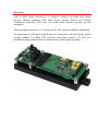
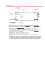
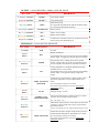
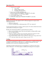
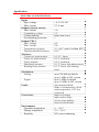
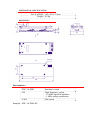
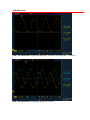
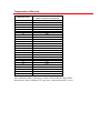
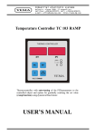
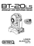
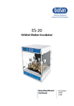
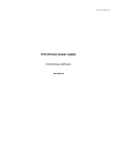
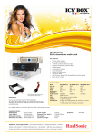
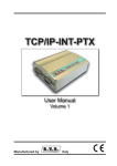
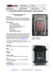
rev 1.07/ 2011 07 07
SDC-1A-PRO diode controller
User Manual
Overview
SDC-1A-PRO diode controller is a complete solution for single laser diode
driving. Module combines both diode driver (current source) and bi-polar
temperature controller (TEC) into one board. Some interface circuits are also
integrated.
Maximal output current is 1A. Current may be CW, analog or digitally modulated.
For operations in CW mode module must be connected to the laser diode, peltier
cooling module, 10 kOhm NTC termistor and power source (+5V DC). For
modulated output module must be connected to external pulse generator.
Description
POWER
SWITCH
FAULT LED
OUTPUT
CURRENT
TRIMPOT
POWER LED
TEMPERATURE
TRIMPOT
INTERFACE
POWER SWITCH – turns module on (to the left) and off (to the right)
CURRENT TRIMPOT – regulates output current (0 – 1A range by default,
other on request), counterclockwise rotation increases the current.
TEMPERATURE TRIMPOT – regulates temperature set point (15 – 40 C
range by default [ with 10 kOhm NTC ], other on request), clockwise
rotation increases the temperature.
POWER LED – indicates if module is turned on
FAULT LED – indicates if module is failed
OUTPUT connector – connects module with diode, peltier module,
10 kOhm NTC and photodiode (adjusted cable is supplied with the module)
INTERFACE connector – transmits input/output signals. Moreover module
is fed through this connector (adjusted cable is supplied with the module)
OUTPUT : 10 PIN WR-PHD 2.54MM, ANGLED, MALE
PIN / TYPE
DESIGNATION
DESCRIPTION
1, 2 (blue) / OUTPUT
DIODE –
Laser diode cathode
3, 4 (red) / OUTPUT
DIODE +
Laser diode anode
Photodiode anode
It’s supposed that photodiode cathode and diode anode
are connected within diode assembly
5 (green) / INPUT
PHD +
6, 7 (purple) / INPUT
NTC RETURN
8 (white) / OUTPUT
TEC –
Peltier cooler module –
9 (orange) / OUTPUT
TEC +
Peltier cooler module +
10 (purple) / INPUT
NTC
Return of NTC
10 kOhm NTC thermistor must be connected to this pin
and to one of NTC RETURN pins
INTERFACE : 10 PIN MOLEX MICROFIT
PIN / TYPE
DESIGNATION
1, 7 (black)
GND
Ground
DM
Digital modulation.
0V applied to this pin (or leaving this pin free-standing)
allows output. 5V applied to this pin suppresses output.
2 (blue)
INPUT
3 (transparent)
OUTPUT
4 (purple)
INPUT
TIMER
AM
5 (yellow)
OUTPUT
TEMP. SET POINT
MONITOR
6 (red)
INPUT
+5V DC
8 (white)
OUTPUT
CURRENT SET
POINT MONITOR
9 (green)
OUTPUT
10 (orange)
OUTPUT
PHD
TEMP. MONITOR
DESCRIPTION
Internal timer shows running hours of the module.
Output voltage at this pin is linear with running hours.
5V corresponds to 10 000 hours, afterthen 5V forever.
Analog modulation. Like digital modulation analog
modulation has reverse polarity.
0V applied to this pin (or leaving this pin free-standing)
allows output. 2.5V applied to this pin suppresses
output.
Temperature set point monitor. Output voltage at this
pin shows temperature set point. Dependence isn’t
linear.
0V corresponds to Tmin, 4V to Tmax.
For Tmin, Tmax and T(V) curve see Temperature
calibration section.
Feeding voltage +5V DC.
Current set point monitor. Voltage at this pin is linear
with the current settled with the trimpot.
0V – 0A, 2.5V – 1A.
Photodiode. If photodiode is connected to the OUTPUT
connector, output voltage at this pin is proportional to
photodiode current.
10mV corresponds to 1uA of photodiode output current.
Temperature monitor. Output voltage at this pin shows
measured diode temperature. Dependence isn’t linear.
0V corresponds to Tmin, 4V to Tmax.
For Tmin, Tmax and T(V) curve see Temperature
calibration section.
Operations (CW)
1. Connect to the module
•
laser diode
•
peltier cooling module
•
10 kOhm NTC thermistor
2. Ensure that POWER SWITCH is off,
Set zero current (turn CURRENT TRIMPOT to the right)
3. Connect module to +5V DC power supply
4. Turn POWER SWITCH on
5. Set desired current (turn CURRENT TRIMPOT to the left)
Faults / Protections
Module sets FAULT state (lights FAULT LED and suppresses output) in the
following situations:
• Diode not connected
• Diode overtemperature, undertemperature, NTC not connected
To start operations again you need to turn the power off, then avoid the fault cause
and afterthen turn the power on again.
Besides abovementioned module is protected from as follows:
• Short-circuited diode output, short-circuited peltier cooling module output
• Reverse input polarity
• Input overvoltage (module stops operations when input voltage exceeds
5.5V and starts again when input voltage falls below 5.3V)
• Input undervoltage (module stops operations when input voltage falls below
4.2V and starts again when input voltage exceeds 5.0V)
Cooling
In standard environmental conditions (0-30ºC temperature, no tight envelopes) no
cooling is needed. Elsewise either passive cooling by mounting onto larger
heatsink or active forced air cooling may be needed.
Optionally 40x40x10 mm fan may be preinstalled as it’s shown on the picture
below. Because of +5V DC fan input, no additional feeding level are required.
Specification
ELECTRICAL SPECIFICATION
Input:
Input voltage
Max. current
Output (current source):
Max. current
Compliance voltage
Current stability
Overshooting protection
Output (TEC):
Max. voltage
Max. current
Temperature set point
Thermocontroller accuracy
Monitors:
Current set point monitor
Temp. set point monitor
Temp. monitor
Photodiode monitor
Running hours monitor
Modulation:
Analog
Digital
Faults:
Protections:
Environment:
Operation temperature
Storage temperature
Humidity
+ 4.2-5.5V DC
2.7 A max
1A
3V
better than 5 mA
+
4V
2A
15 – 40 C (with 10 kOhm NTC)
0.1 C
0-2.5 V, linear
0-4 V, nonlinear
0-4 V, nonlinear
0-5 V, linear with photocurrent
0-5 V, linear with running
hours
up to 300 kHz by default
up to 1 MHz in -HF version
up to 3 MHz by default
up to 10 MHz in -HF version
not connected diode
diode overtemperature, diode
undertemperature, NTC not
connected
input overvoltage
input undervoltage
reverse input polarity
short-circuited loads
0…+40 C
-20…+60 C
90%, non-condensing
MECHANICAL SPECIFICATION
Size (LxWxH) 105 x 40 x 27 mm
Weight 0.2 kg
10
5
27
DRAWINGS
40
A
M3 (x4)
30
A
70
105
Part numbers
SDC-1A-PRO
-HF
-FAN
Example : SDC-1A-PRO-HF
Standard version
High frequency option
- 10 MHz digital modulation
- 1 MHz analog modulation
Fan option
Miscellaneous
SDC-1A-PRO-HF: Digital modulation, 10 MHz, rise/fall time ~30-40 ns
SDC-1A-PRO-HF: Analog modulation, 1 MHz
Temperature calibration
TEMPERATURE
TEMP. MONITOR /
TEMP. SET POINT MONITOR
15
16
17
18
19
20
21
22
23
24
25
26
27
28
29
30
31
32
33
34
35
36
37
38
39
40
4,09
3,92
3,74
3,57
3,4
3,23
3,06
2,89
2,72
2,55
2,38
2,21
2,04
1,88
1,71
1,55
1,39
1,23
1,07
0,91
0,76
0,61
0,47
0,32
0,18
0,03
This calibration table is absolutely valid for EPCOS B57861S0103F040
thermisotors. Other 10kOhm NTC may have a little different R/T curves.