1
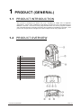
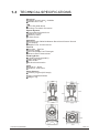
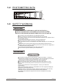
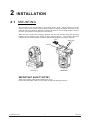
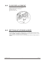
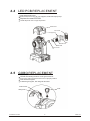
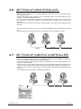
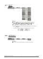
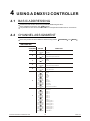
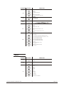
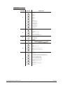
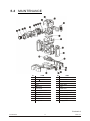
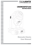
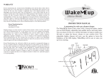
75
USER
MANUAL
Ver 1,0
T
ABLE OF CONTENTS
PART 1 PRODUCT (GENERAL)................................................................. 1.
1.1--PRODUCT INTRODUCTION........................................................................1.
1.2-- PRODUCT OVERVIEW................................................................................1.
1.3--TECHNICAL SPECIFICATIONS................................................................... 2.
1.4--PHOTOMETRIC DATA.................................................................................3.
1.5--SAFETY WARNING.....................................................................................3.
PART 2 INSTALLATION ........................................................................... 4.
2.1-- MOUNTING ................................................................................................4.
2.2-- FUSE REPLACEMENT............................................................................... 5.
2.3-- SETTING UP (STAND ALONE).................................................................... 5.
2.4-- LED PCB REPLACEMENT .......................................................................... 6.
2.5-- GOBO REPLACEMENT ............................................................................... 6.
2.6-- SETTING UP (MASTER/SLAVE).................................................................. 7.
2.7-- SETTING UP (DMX512 CONTROLLER)....................................................... 7.
PART 3 DISPLAY PANEL OPERATION....................................................... 8.
3.1--BASIC........................................................................................................8.
3.2--MENU........................................................................................................ 8.
3.3-- INTRO ....................................................................................................... 10.
3.4-- INVERT ......................................................................................................10.
3.5-- RANGE ......................................................................................................11.
3.6-- SPECIAL ................................................................................................... 11.
3.7-- EDIT ..........................................................................................................12.
3.8-- DEFAULT .................................................................................................. 12.
PART 4 USING A DMX512 CONTROLLER...................................................13.
4.1--BASIC ADDRESSING................................................................................. 13.
4.2--CHANNEL ASSIGNMENT............................................................................ 13.
PART 5 APPENDIX................................................................................... 16.
5.1-- TROUBLE SHOOTING................................................................................ 16.
5.2-- MAINTENANCE .......................................................................................... 17.
1
PRODUCT (GENERAL)
1.1
PRODUCT INTRODUCTION
This product is designed for indoor use only. Suitable for stage, bar or nightclub
applications. Direct input of DMX512 signal allows the fixtures to be controlled from any
DMX512 controller. The fixture is fully programmable with one custom program available
and is supplied with two automatic programs (all accessible from DMX512 controller). This
product can be operated as a single unit or with multiple units for large applications.
1.2
PRODUCT OVERVIEW
No
ITEM
1
Head
2
Arm
3
Base
4
Menu
5
Enter
6
Down
7
Up
8
Switch
9
Fuse
10
Power input
11
DMX 3-PIN signal output
12
DMX 3-PIN signal input
1 PRODUCT(GENERAL)
1
2009.2.8
1.3
TECHNICAL SPECIFICATIONS
Electrical
Voltage:AC100~240V 50/60Hz
Rated Power:75W
LED
LED:1PC(20W white)
Cooling:Forced air convection
Optical System
Focus:Manual linear focus
Dimmer:0~100%
Strobe:0~20Hz
3-facet Prism
Operation
Control mode: DMX512/Master-Slave/Auto/Custom/ Sound
LCD display
DMX512 Chs: 9 CHS/12CHS
Pan/Tilt
Pan 540 Tilt 270
Pan/Tilt speed
User-selectable Pan/Tilt ranges
Reverse Pan/Tilt movement
Rotating Gobo
7 Gobo (interchangeable)
Gobo-flow effect
Gobo shake
Bi-directional rotation
Color
9 dichroic - filters
Rainbow - flow effect
Other features
Custom program (255 steps)
Size: 240x200x3540mm
Weight: 7kg
1 PRODUCT(GENERAL)
2
2009.2.8
1.4
PHOTOMETRIC DATA
2000
588
256
147
2(0.5)
4(1.1)
6(1.7)
8(2.2)
1.5
16
0
97 LUX
10Distance(m)
2.8 Diameter(m))
SAFETY WARNING
IMPORTANT
ALWAYS READ THE USER MANUAL BEFORE OPERATION.
PLEASE CONFIRM THAT THE POWER SUPPLY STATED ON THE
PRODUCT IS THE SAME AS THE MAINS POWER SUPPLY IN YOUR AREA.
This product must be installed by a qualified professional.
Always operate the equipment as described in the user manual.
A minimum distance of 0.5m must be maintained between the equipment and
combustible surface.
The product must always be placed in a well ventilated area.
Always make sure that the equipment is installed securely.
DO NOT stand close to the equipment and stare directly into the LED light
source.
Always disconnect the power supply before attempting and maintenance.
Always make sure that the supporting structure is solid and can support the
combined weight of the products.
The earth wire must always be connected to the ground.
Do not touch the power cables if your hands are wet.
ATTENTION
This product left the place of manufacture in perfect condition. In order to
maintain this condition and for safe operation, the user must always follow the
instructions and safety warnings described in this user manual.
Avoid shaking or strong impacts to any part of the equipment.
Make sure that all parts of the equipment are kept clean and free of dust.
Always make sure that the power connections are connected correct and
secure.
If there is any malfunction of the equipment, contact your distributor
immediately.
When transferring the product, it is advisable to use the original packaging in
which the product left the factory.
Shields, lenses or ultraviolet screens shall be changed if they have become
damaged to such an extent that their effectiveness is impaired.
The lamp (LED) shall be changed if it has become damaged or thermally
deformed.
1 PRODUCT(GENERAL)
3
2009.2.8
2
2.1
INSTALLATION
MOUNTING
The LED fixture can be operated in any position at any angle. When mounted on a flat
surface, the surface must be strong enough to support 10 times the weight of the fixture and
stable so that there will be no damage caused to the fixture or surrounding people or objects
because of movements of the fixture on the surface.
When the unit is mounted in a hanging position, the fixture is attached using the mounting
brackets and a standard truss clamp or other clamping device. The mounting brackets
supplied are mounted using quick-release locks allowing simple mounting or removal.
Clamp
Safety cable
Bracket
HANGING
UPRIGHT
IMPORTANT SAFETY NOTE!!
Always use a safety cable when installing this unit!!
Be sure that the safety cable is connected to a solid load-bearing structure.
2 INSTALLATION
4
2009.2.8
2.2
FUSE REPLACEMENT
Remove the safety cap by a screwdriver.
F etch the old fuse from safety cap.
I nstall a new fuse.
I nstall the safety cap.
Safety Cap
Fuse
2.3
SETTING UP (STAND ALONE)
The LED fixture can be used as a stand alone unit. The stand alone functions AUTO 1,
AUTO 2, SOUND 1, SOUND2 and CUSTOM can be activated without the need to connect
to any controller or connecting to any other equipment.
Simply, access the <operation> menu from the DISPLAY and select the target program to
activate.
2 INSTALLATION
5
2009.2.8
2.4
LED PCB REPLACEMENT
Take off the head cover.
Remove the fan cover, fan, fan supports, heat sink step by step.
Replace the new LED PCB.
I nstall all parts on the original position.
Head cover
Fan cover
Fan supports
Fan
Heat sink
LED PCB
23 lenses
2.5
GOBO REPLACEMENT
Unlock the sliding the knob on the gobo slot door.
Pull up the gobo slot door and turn it to a proper position.
Take out the bad gobo.
Install the good gobo, lock the gobo slot door.
Gobo slot door
Gobo
Sliding knob
2 INSTALLATION
6
2009.2.8
2.6
SETTING UP (MASTER/SLAVE)
When units are connected in series using DMX512 signal cable connect the units as shown
in the diagram below
Connect the (male) 3 pin connector side of the DMX cable to the output (female) 3 pin
connector of the first (MASTER) fixture.
Connect the end of the cable coming from the MASTER fixture which will have a (female) 3
pin connector to the input connector of the next fixture consisting of a (male) 3 pin
connector.
Then proceed to connect from the output as stated above to the input of the following fixture
and so on.
Set the first unit in the series to one of the STAND ALONE modes as described in section
2.2
All other units in the series should be set to <SLAVE> from the <operation> menu.
MASTER
2.7
SLAVE
SLAVE
SETTING UP (DMX512 CONTROLLER)
When units are connected in series to a DMX512 controller and other DMX512 equipment,
connect the equipment as shown in the diagram below.
Connect the (male) 3 pin connector side of the DMX cable to the output (female) 3 pin
connector of the controller.
Connect the end of the cable coming from the controller which will have a (female) 3 pin
connector to the input connector of the next fixture consisting of a (male) 3 pin connector.
Then proceed to connect from the output as stated above to the input of the following fixture
and so on.
If over 32pcs fixtures connected ,the amplifier is needed.
DMX512
CONTROLLER
2 INSTALLATION
7
2009.2.8
3
3.1
DISPLAY PANEL OPERATION
BASIC
The LED fixture is mounted with a LCD display and 4 control buttons.
MENU
ENTER
DOWN
UP
MENU Scroll through the main menu or exit from the current sub-menu
ENTER Enter the currently selected menu or confirm the current function value
DOWN Scroll 'DOWN' through the menu list or decrease the value of the current function
UP
Scroll 'UP' through the menu list or increase the value of the current function
3.2
MENU
MENU
Intro
Address
(001~512)
Reset
Yes
No
Run
DMX512
Auto 1
Auto 2
Sound 1
Sound 2
Custom
Test
Slave
Channels
Basic
Advanced
Invert
Display
60 close
Bright
Info
Edition
Pan
Normal
Reverse
Tilt
Normal
Reverse
Color
Step
Linear
Use
No
Yes
3 DISPLAY PANEL OPERATION
8
2009.2.8
Range
P/start
(000~255)
P/Finish
(000~255)
T/start
(000~255)
T/Finish
(000~255)
Use
No
Yes
Special
Edit
Default
3 DISPLAY PANEL OPERATION
9
Black
No
Yes
Reset
Dmx
System
Step
(000~255)
Pan
(000~255)
Tilt
(000~255)
Speed
(000~255)
Color
(000~255)
Gobo
(000~255)
Gobo.rot
(000~255)
Prism
(000~255)
Dimmer
(000~255)
Strobe
(000~255)
Time
(000~255)
Use
No
Yes
Default
No
Yes
2009.2.8
3.3
INTRO
MENU
Intro
Address
(001~512)
Reset
Yes
No
Run
DMX512
Auto 1
Auto 2
Sound 1
Sound 2
Custom
Test
Slave
Channels
Basic
Advanced
Address
Enter Address
Display
60 close
Bright
Info
Edition
to set the DMX Address, which is from (001-512)
Reset
In order to rest custom modest to default, select
Reset
Run
Enter Run to select the operation mode: DMAX512 ; Auto1 ;
Auto2 ; Sound 1 ; Sound 2 ; Custom ; Test ; Slave
Channels
Enter Channels
Display
Enter Display
Info
Enter
3.4
Info
to select the DMX channel modes: Basic ;
Advanced .
to select the lighting time of the LCD display panel.
to see the version of the software.
INVERT
MENU
Pan
Invert
Normal
Reverse
Tilt
Normal
Reverse
Color
Step
Linear
Use
No
Yes
Invert
Select Pan / Tilt to set Normal or Reverse
Select Color to select the color wheel flow way Step
Enter Use and set Yes to run the new setting
3 DISPLAY PANEL OPERATION
10
or
linear
2009.2.8
3.5 RANGE
MENU
Range
P/start
(000~255)
P/Finish
(000~255)
T/start
(000~255)
T/Finish
(000~255)
Use
No
Yes
P/start
Set pan start value
P/Finish
Set pan finish value
T/start
Set Tilt start value
T/Finish
Set Tilt finish value
Use
Enter
3.6
Use
000~255
000~255
000~255
000~255
and select Yes to open the operation of X/Y angle
SPECIAL
MENU
Special
Black
Enter Black
delay
to choose
Black
No
Yes
Reset
Dmx
System
No
Reset
Enter Reset to choose DMX
cannot control reset
3 DISPLAY PANEL OPERATION
11
without delay or
Yes
DMX control reset or
3seconds
System
DMX
2009.2.8
3.7
EDIT
MENU
Edit
Step
(000~255)
Pan
(000~255)
Tilt
(000~255)
Speed
(000~255)
Color
(000~255)
Gobo
(000~255)
Gobo.rot
(000~255)
Prism
(000~255)
Dimmer
(000~255)
Strobe
(000~255)
Time
(000~255)
Use
No
Yes
Edit
Enter the Edit mode to edit the custom programs by adjusting the
value of Step , Pan , Tilt , Speed , Color , Gobo ,
Gobo.rot , Prism , Dimmer , Strobe , Time
Enter Use and select Yes to run the steps user need.
Note: if user want to circulate the created steps, please set the last step s
T ime as 0
For example, there are 3 steps, the setting should be like belowed:
Step 1 T ime = 4
Use = Yes
Step 2 T ime = 5
Use = Yes
Step 3 T ime = 0
Use = Yes
3.8
DEFAULT
MENU
Default
Default
No
Yes
Default
This functions will reset all setting to the original factory setting
3 DISPLAY PANEL OPERATION
12
2009.2.8
4
4.1
USING A DMX512 CONTROLLER
BASIC ADDRESSING
Connect all of the units in series using standard DMX512 signal cable .
Set the DMX512 address in the DMX menu.
It is possible to have the same DMX address or independent addresses for each fixture.
4.2
CHANNEL ASSIGNMENT
Note: This product have two DMX512 channel configuration:
ADVANCED
and
BASIC .
ADVANCED
CHANNEL
1
VALUE
FUNCTION
PAN
0
0~ 54 0
255
PAN FINE
2
Fine control of pan movement
0
255
0
255
0
255
Fine control of tilt movement
0
255
From fast to slow
0
14
15
29
30
44
45
59
60
74
75
89
TILT
3
0~270
TILT FINE
4
PAN/TILT SPEED
5
6
90
104
COLOR WHEEL
White
Red
Yellow
Green
Pink
Blue
Orange
105
119
Magenta
120
134
light blue
135
149
light green
150
255
Rainbow & linear effect
GOBO WHEEL 1 & GOBO SHAKE
0
7
4 USING A DMX512 CONTROLLER
9
NO Gobo
10
19
Gobo 1
20
29
Gobo 2
30
39
Gobo 3
40
49
Gobo 4
50
59
Gobo 5
60
69
Gobo 6
70
79
Gobo 7
80
99
Shaking gobo 7
100
119
Shaking gobo 6
120
139
Shaking gobo 5
140
159
Shaking gobo 4
160
179
Shaking gobo 3
180
199
Shaking gobo 2
200
219
Shaking gobo 1
220
255
Flow effect
13
2009.2.8
CHANNEL
VALUE
FUNCTION
GOBO ROTATION
8
0
2
Stop
3
6
7
128
129
132
Slowest
Rotate from slow to fast
Stop
133
136
137
255
0
127
128
255
Reverse rotate slowest
Reverse rotate from slow to fast
PRISM
9
NO FUNCTION
In 3-facet prism
DIMMER
10
0
255
0
31
Close
32
63
Open
64
95
Strobe: Slow > Fast
96
127
Open
128
159
Rulse strobe effect: Slow > Fast
160
191
Open
192
223
Random strobe effect: Slow > Fast
224
255
Open
Dark
Bright
STROBE
11
CONTROL
12
0
19
No function
20
39
Pan/tilt black activated (activated after 3 secs)
40
59
Pan/tilt black deactivated (activated after 3 secs)
60
79
Auto1 (activated after 3 secs)
80
99
Auto2 (activated after 3 secs)
100
119
Sound 1(activated after 3 secs)
120
139
Sound 2(activated after 3 secs)
140
159
Custom
160
179
Test (activated after 3 secs)
180
199
No function
200
219
Reset (activated after 3 secs)
220
255
No function
BASIC
CHANNEL
1
VALUE
FUNCTION
PAN
0
255
0~ 54 0
0
255
0~270
0
14
15
29
30
44
45
59
60
74
75
89
TILT
2
3
4 USING A DMX512 CONTROLLER
90
104
COLOR WHEEL
White
Red
Yellow
Green
Pink
Blue
Orange
105
119
Magenta
120
134
light blue
135
149
light green
150
255
Rainbow & linear effect
14
2009.2.8
BASIC
CHANNEL
VALUE
FUNCTION
GOBO WHEEL 1 & GOBO SHAKE
0
4
9
NO Gobo
10
19
Gobo 1
20
29
Gobo 2
30
39
Gobo 3
40
49
Gobo 4
50
59
Gobo 5
60
69
Gobo 6
70
79
Gobo 7
80
99
Shaking gobo 7
100
119
Shaking gobo 6
120
139
Shaking gobo 5
140
159
Shaking gobo 4
160
179
Shaking gobo 3
180
199
Shaking gobo 2
200
219
Shaking gobo 1
220
255
Flow effect
GOBO ROTATION
5
0
2
Stop
3
6
7
128
129
132
Slowest
Rotate from slow to fast
Stop
133
136
137
255
0
127
128
255
Reverse rotate slowest
Reverse rotate from slow to fast
PRISM
6
NO FUNCTION
In 3-facet prism
DIMMER
7
0
255
Dark
Bright
STROBE
8
0
31
Close
32
63
Open
64
95
Strobe: Slow > Fast
96
127
Open
128
159
Rulse strobe effect: Slow > Fast
160
191
Open
192
223
Random strobe effect: Slow > Fast
224
255
Open
CONTROL
9
4 USING A DMX512 CONTROLLER
0
19
No function
20
39
Pan/tilt black activated (activated after 3 secs)
40
59
Pan/tilt black deactivated (activated after 3 secs)
60
79
Auto1 (activated after 3 secs)
80
99
Auto2 (activated after 3 secs)
100
119
Sound 1(activated after 3 secs)
120
139
Sound 2(activated after 3 secs)
140
159
Custom
160
179
Test (activated after 3 secs)
180
199
No function
200
219
Reset (activated after 3 secs)
220
255
No function
15
2009.2.8
5
APPENDIX
5.1
TROUBLE SHOOTING
SITUATION
No power
LED not lit
CAUSE
ACTION
Power connection error
Check all Power connectons
Fuse damaged
Replace Fuse
Power supply damaged
Replace Power supply
Power switch damaged
Replace Power switch
LED driver PCB damaged
Replace LED driver PCB
LED PCB damaged
Replace LED PCB
LED PCB connection error
Check the connections
Fan # (60x60x20)
Head fan error
Fan do not work
Base fan error
Fixture reset normal,
But not be controlled
Replaced Display PCB
DMX PCB damaged or DMX signal
connection error
Check DMX signal connection
or replace DMX PCB
Pan movement error
Tilt movement error
5 APPENDIX
LED607 CONTROL PCB ERROR
Rotating gobo wheel error
Check the power supply
Display PCB damaged
Prism error
Color wheel error
Check the LED driver PCB
Fan #(40x40x10)
Motor damaged
Replace motor
Prism belt broken
Replace belt
Motor damaged
Replace motor
Sensor PCB damaged
Replace sensor
Motor damaged
Replace motor
Rotating Gobo wheel blocked
Check or replace the gobo wheel
Sensor PCB damaged
Replace the sensor
Motor damaged
Replace Pan motor
Pan belt broken
Replace pan belt
Magnetic sensor PCB damaged
Replace the magnetic sensor
Optical sensor damaged
Replace the optical sensor
Motor damaged
Replace Tilt motor
Tilt belt broken
Replace tilt belt
Magnetic sensor PCB damaged
Replace the magnetic sensor
Optical sensor damaged
Replace the optical sensor
16
2009.2.8
5.2
MAINTENANCE
No
ITEM
No
ITEM
1
Front lense cover
13
Head fan cover
2
Front
14
Control PCB
3
Mouth cover
15
Head cover A
Prism
16
Driver PCB
32 lense
17
Arm
6
Color wheel
18
Base cover
7
Rotating Gobo wheel
19
DMX socket (Female)
20
DMX socket (Male)
LED PCB
21
Power on/off
10
Head cover B
22
Power socket
11
Gobo slot door
23
Power supply
12
Sliding knob
24
Display PCB
4
5
8
9
42 lense
23 lense
Version 1.0
5 APPENDIX
17
2009.2.8