1
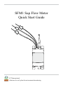
SFM1 Sap Flow Meter Quick Start Guide ICT International Solutions for soil, plant & environmental monitoring Contents Quick Start Guide................................................................................................4 1 SFM1 Start Up Check List......................................................................5 2 2.1 2.2 2.3 System Requirements...............................................................................6 CPU Processor............................................................................................6 Software......................................................................................................6 Screen Resolution.......................................................................................6 3 3.1 3.1.1 3.1.2 3.1.3 3.1.4 3.1.5 3.1.6 Charge the SFM1 Internal Battery.........................................................7 Connecting a Power Supply to the Instrument...........................................8 Individual Power Supply Connections.......................................................8 Shared Power Supply for Multiple Instruments.........................................9 Connecting Power Directly via Solar Panel................................................10 Connecting Power via External 12V Battery..............................................11 Connecting Power via External 12V Battery and Solar Panel....................12 Sharing an External 12V Battery and Solar Panel via Daisy Chaining......13 4 Install the SFM1 Software & USB Driver...............................................14 5 Turn the Instrument On...........................................................................14 6 6.1.1 6.1.2 6.1.3 6.1.4 6.2 6.2.1 6.2.2 6.2.3 Connect to the Instrument.......................................................................15 Connect Via USB........................................................................................16 Software Procedure Step 1:.........................................................................17 Software Procedure Step 2:.........................................................................18 Software Procedure Step 3:.........................................................................19 Alternatively, if you are using an MCC1 wireless Radio Modem..............20 Connecting the Wireless Hardware via a USB Cable.................................20 Software Procedure Step 1:.........................................................................21 Software Procedure Step 2:.........................................................................23 7 Instrument Information...........................................................................24 8 Set Date & Time.........................................................................................25 9 9.1 9.2 9.3 9.4 Set Logging Options..................................................................................26 Probe Selection............................................................................................26 Calculated Results.......................................................................................26 Power Management....................................................................................26 Raw Temperature Mode..............................................................................27 ICT International Solutions for soil, plant & environmental monitoring 2 10 10.1 10.2 10.3 10.4 Set the Measurement Control..................................................................28 Needle Temperature Mode..........................................................................28 Sap Flow Mode...........................................................................................28 Measurement Mode....................................................................................29 Test Instrument integrity prior to deployment in the field..........................30 11 Corrections................................................................................................30 11.1 Probe Spacing.............................................................................................30 11.2 Base-line asymmetry Multipliers................................................................31 11.3 Base-line asymmetry offsets.......................................................................31 11.4 Thermal Diffusivity.....................................................................................31 11.5 Wounding Coefficient.................................................................................31 11.6Vs Factor......................................................................................................32 11.7 Sap Wood Area............................................................................................32 12 12.1 12.2 12.3 12.4 12.5 12.6 12.7 12.8 12.9 12.10 Install the Sensor.......................................................................................33 Measure Bark Depth...................................................................................33 Determine Sapwood Thickness...................................................................34 Attach Installation Guide............................................................................36 Begin Drilling.............................................................................................37 Check the holes are Parallel........................................................................37 Use Spacers.................................................................................................38 Grease Needles............................................................................................39 Insert Needles and attach SFM1 to Tree.....................................................40 Insulate Needles on Small Diameter Stems................................................41 Uninstall- Removal.....................................................................................42 13 Download Data..........................................................................................43 13.1 Download Data via USB Cable..................................................................43 13.2 Download MicroSD Card via USB Adapter...............................................45 14 Analyse Data..............................................................................................47 15 Appendix A................................................................................................48 16 Contact Details..........................................................................................49 ICT International Solutions for soil, plant & environmental monitoring 3 Quick Start Guide NOTE: This manual should be used in conjunction with the instructional videos provided by ICT International to compliment each section of operation. These videos are located on the ICT YouTube site http://www.youtube.com/user/ictintl WARNING – The measurement needles of the SFM1 are made of hollow 1.3 mm stainless steel tubing. They can easily be bent, damaged or broken off if basic care is not taken in handling the instrument. ICT International Solutions for soil, plant & environmental monitoring 4 1 SFM1 Start Up Check List ! WARNING! Please Read, Understand and Complete this checklist before unpacking the SFM1 Sap Flow Meter! Have you read the manual? http://www.ictinternational.com/techhelp/sfm1manual.html Have you watched the videos? http://www.youtube.com/user/ictintl If you are unsure about anything regarding your Sap Flow Meter contact ICT International before use. [email protected] +61 2 6772 6770 ICT International Solutions for soil, plant & environmental monitoring 5 2 System Requirements 2.1 CPU Processor The ICT Instrument software does not require large processing power. For example it is compatible with NetBooks. Minimum Recommended Processor Capacity: Intel Atom Processors with a CPU N270 @ 1.66 GHz and 1GB RAM or higher. 2.2Software The ICT Instrument software is compatible with the following Windows Operating Systems: a. Windows XP b. Windows Vista c.Windows7 d. Windows Virtual OS run from a Mac computer 2.3 Screen Resolution The ICT Instrument software is written to a fixed screen resolution of 857 x 660 dpi (it does not Auto Resize) and works best on current model laptops that have a screen size of 11.6” or larger and a default screen resolution of 1366 x 768 (the vertical height of 768 being most important otherwise you can't see the bottom of the software). ICT International Solutions for soil, plant & environmental monitoring 6 3 Charge the SFM1 Internal Battery The SFM1 is a self contained instrument that incorporates a lithium polymer battery. Before using the instrument, this battery MUST be charged. To choose from a range of charging options see Connecting a Power Supply to the Instrument (pages 10 to 13). The unique power-bus plug design was developed by ICT International to simplify the electrical wiring process. It minimises the need for custom tools in the field requiring only that the outer cable sheath be stripped back to expose the copper wire. See section Connecting a Power Supply to the Instrument (page 8) no other tools are required with all necessary components and fixings fully incorporated into the instrument design. Retaining straps ensure the power-bus plugs do not separate from the instrument when removed from the power-bus during wiring preparation and connection of external power. ICT International Solutions for soil, plant & environmental monitoring 7 3.1 Connecting a Power Supply to the Instrument 3.1.1 Individual Power Supply Connections Important: Do not connect external power until the final step 1 7 8 2 9 3 4 10 5 6 ICT International Solutions for soil, plant & environmental monitoring 8 3.1.2 Shared Power Supply for Multiple Instruments ICT International Solutions for soil, plant & environmental monitoring 9 3.1.3 Connecting Power Directly via Solar Panel Note: The SFM1 Sap Flow Meter is non-polarized SFM1 Solar Panel ICT International Solutions for soil, plant & environmental monitoring 10 3.1.4 Connecting Power via External 12V Battery Note: The SFM1 Sap Flow Meter is non-polarized SFM1 External 12V Battery ICT International Solutions for soil, plant & environmental monitoring 11 3.1.5 Connecting Power via External 12V Battery and Solar Panel Note: The SFM1 Sap Flow Meter is non-polarized Note: The External 12V Battery is polarized SFM1 Solar Panel Solar Regulator External 12V Battery ICT International Solutions for soil, plant & environmental monitoring 12 3.1.6 Sharing an External 12V Battery and Solar Panel via Daisy Chaining Note: The SFM1 Sap Flow Meter is non-polarized SFM1 SFM1 SFM1 Solar Panel Solar Regulator Note: The External 12V Battery is polarized External 12V Battery ICT International Solutions for soil, plant & environmental monitoring 13 4 Install the SFM1 Software & USB Driver Insert the supplied DVD into the computer. The DVD will auto-run to present a menu. Choose software (a) then choose USB Driver (b) and then SFM1 Installation Software (c). (b) (a) (c) The SFM1 Sap Flow Meter software can also be downloaded from the ICT International Software Downloads Page. 5 Turn the Instrument On The Sap Flow Meter has an internal 4V 1 Amp DC Lithium Polymer battery that is used to operate the instrument. The internal battery must be trickle charged from an external power source (such as a Solar Panel) for long term field deployment. The Sap Flow Meter can be turned on manually by pressing the power button or automatically by connecting an external 12V DC power supply. This includes a USB cable connected to a PC. The SFM1 can also be charged directly from any computer’s USB port. When the instrument is turned on the Green light (visible through the light tube, adjacent to the communication port) will flash rapidly for a few seconds during start up. Once the SFM1 has started the green light will flash momentarily once every 10 seconds to indicate it is on. ICT International Solutions for soil, plant & environmental monitoring 14 6 Connect to the Instrument Connect the USB cable to the instrument. The SFM1 will automatically be detected by the computer as with any USB device. Double click the SFM1 icon on the Desktop to open the software. On/Off Switch USB Port SD Card LED ICT International Solutions for soil, plant & environmental monitoring 15 6.1.1 Connect Via USB Connect the USB cable to the instrument. The SFM1 will automatically be detected by the computer as with any USB device. Double click the SFM1 icon on the Desktop to open the software. Double Click the SFM1 Icon SFM1 USB Cable ICT International Solutions for soil, plant & environmental monitoring 16 6.1.2 Software Procedure Step 1: Click the icon “Connect to SFM1”, then click “Find Devices” to search for the instrument and select the named instrument from the Available Devices within the Device Selection Window. Click the icon “Connect to SFM” ICT International Solutions for soil, plant & environmental monitoring 17 6.1.3 Software Procedure Step 2: You must first choose the connection type “USB” then Click “Find Devices” to search for the instrument. ICT International Solutions for soil, plant & environmental monitoring 18 6.1.4 Software Procedure Step 3: You must click on device and highlight. After you highlight the device then click “Select Device”. ICT International Solutions for soil, plant & environmental monitoring 19 6.2 Alternatively, if you are using an MCC1 wireless Radio Modem 6.2.1 Connecting the Wireless Hardware via a USB Cable Connect the MCC1 to a computer via a USB cable. Double click the SFM1 icon on the Desktop to open the software and click the icon “Connect to SFM1”. Double Click the SFM1 Icon USB Cable MCC1 SFM1 ICT International Solutions for soil, plant & environmental monitoring 20 6.2.2 Software Procedure Step 1: Change the Connection Type from USB to RF Modem and click “Find Devices”. When ICT Compatible RF Modem appears double click on it to bring up the RF Devcie Chooser Window. Make sure device is selected. Choose the connection type “RF” then Click “Find Devices” to search for the instrument. ICT International Solutions for soil, plant & environmental monitoring 21 The software performs a wakeup routine then searches for instruments within range. ICT International Solutions for soil, plant & environmental monitoring 22 6.2.3 Software Procedure Step 2: Click on Device. After you highlight the device then click “Connect”. ICT International Solutions for soil, plant & environmental monitoring 23 7 Instrument Information Fields are provided to Name the instrument and attach a Comment. Entries in these fields will be recorded in a header line within the data file and can be beneficial to recalling important aspects of the experiment after data has been collected. Every time these fields are changed the change is automatically recorded in a new header line entry in the data file. The name should be indicative of the instrument or treatment and identify its location, as it is the Name field which is displayed (along with the serial number) when connecting to the instrument. This is especially valuable if connecting wirelessly to the instrument. To edit the field click on the X to the right hand side to clear the field and begin typing. Then click the update sensor information icon to save the change. ICT International Solutions for soil, plant & environmental monitoring 24 8 Set Date & Time The date and time are accessed via commands menu along the top menu bar of the SFM1 software. The date and time can be automatically set to the date & time of the computer the SFM1 is connected to by selecting the option Update Computer Time. An alternative option is provided to update the instrument to a user defined time. This is very important as Sap Flow Meters are often deployed in regions distant to your usual office or time zone. The day, month and year can be set by clicking on the cell and using the arrows to scroll to the required values. This is the same for both hours and minutes. Alternatively, you can type the value directly into each cell. Then click update and the new date & time will be saved to the real time clock of the SFM1’s microprocessor. ICT International Solutions for soil, plant & environmental monitoring 25 9 Set Logging Options 9.1 Probe Selection The SFM1 can be configured to measure both Inner & Outer radial measurement points, needle, or either the Inner or the Outer measurement point independently of the other. This is useful when working with small stems. Typically, the needle would be inserted all the way through the stem to ensure mechanical strength and minimise the leverage effect of having only the needle tip inserted into the stem. Therefore, just logging the outer measurement point would be most common in small stems. Nevertheless, the options to measure just the inner measurement point is available. 9.2 Calculated Results The SFM1 can log and process raw data on board the instruments Microprocessor. To do this, simply check all the boxes for calculated results. Whilst the SFM1 will process and log the data to file, for the data to be meaningful you must have entered all the necessary correction parameters (page 29) first. 9.3 Power Management The SFM1 can log the instruments internal battery voltage, the external charging supply voltage and external charging current. These parameters should always be logged to aid in trouble shooting spurious results that typically can be caused by power supply issues. ICT International Solutions for soil, plant & environmental monitoring 26 9.4 Raw Temperature Mode The needle temperatures mode is for advanced research applications in which the shape of the heat pulse and the timing of events within the heating and cooling of the stem which to be analysed using alternative equations, in addition to basic sap flow measurements. Please refer to the full User Manual for more details. The Screen shot on the right (below) is the recommended configuration for most sap flow applications in that it is logging raw heat pulse velocity on both Inner & Outer measurement points of the needles and all processing of data will be completed in SFT software as all correction factors are determined as the experiment progresses. The SD Card Logging Options Menu is again accessed via the commands menu along the top menu bar of the SFM1 software. Different reporting option recommended for needle temperature mode. ICT International Solutions for soil, plant & environmental monitoring 27 10 Set the Measurement Control The SFM1 Sap Flow Meter provides two Reporting Options; Needle Temperature Mode or Sap Flow Mode. 10.1 Needle Temperature Mode Is highly recommended for detailed scientific research. The raw needle temperatures measured throughout the measurement cycle are recorded at a typical frequency of 3 Hz, although the user can adjust this between 1 and 30 Hz). This mode then provides internal stem temperatures at two points radially across the sap wood and the data can be post processed in Sap Flow Tool Software. The advantage of this feature is that correction parameters can be collected subsequent to installation (rather than prior to) and that data can be reprocessed at any time instantly should any correction parameter be revised. Additionally, Sap Flow Tool provides the ability analyse the raw heat pulse data with a range of sap flow algorithms (HRM, HRMx, CHPM1 or TMax) 10.2 Sap Flow Mode This provides automatically processed sap flow results in Raw Heat Pulse Velocity, Corrected Sap Velocity and Sap Flow. The Raw Heat Pulse Velocity can be used in Sap Flow Tool Software to post process the data however, Corrected Sap Velocity and Sap Flow cannot be reprocessed once logged in these units. In order to use the Corrected Sap Velocity and Sap Flow data automatically logged by the Sap Flow Meter, you must enter the relevant correction parameters into 1 depending upon the configuration of the needle set ICT International Solutions for soil, plant & environmental monitoring 28 the Corrections tab to enable the onboard processing of the measured raw data. This feature is suitable where a great prior knowledge about the species being measured is known, or indicative values of sap flow without the necessity for absolute precision and accuracy of sap flow data is needed quickly. 10.3 Measurement Mode The Heat Ratio Method involves a pulse of heat input to the water conducting xylem or sapwood of the plant to measure the flow of water. In order not to compound the effect of the heat pulse it is recommended to allow time for the heat to move through the system. Typically 10 minutes is adequate to achieve this and, as such is the minimum recommended logging interval. Shorter logging intervals are possible for academic research purposes. Other typical logging intervals such as 15 minutes, 20, 30 and 60 minute intervals are available from the drop down box. Note: when changing the logging interval it is necessary to click the “Update Measurement Options” icon to make the change take effect. ICT International Solutions for soil, plant & environmental monitoring 29 10.4 Test Instrument integrity prior to deployment in the field A manual measurement mode is also available which is convenient for testing instrument operation and integrity testing of the needles prior to field deployment. Use the HRM30-TB Test Block to confirm the integrity of the needles and the instrument prior to deployment in the field. The Test Block has been engineered to force a known sap velocity when a manual measurement is made. If the instrument does not return a sap velocity within the range 12 to 18 cm hr (please contact ICT international via our web site www.ictinternational.com and submit a ticket explaining the issue and request an RMA# via the Service Desk), this test provides confidence that the instrument is fully functional before leaving for a (typically remote) field site. 11Corrections The correction parameters are used when the SFM1 Sap Flow Meter is used to process data on board without the aid of Sap Flow Tool software. 11.1 Probe Spacing Probe spacing must be set to the distance between the needles as they were installed in the stem as this parameter is used in the HRM Algorithm. • Where: • k is the thermal diffusivity of wet wood • x is the distance between the heat source (heater) and temperature sensors • v1 and v2 are the increases in temperature (from ambient) at equidistant points downstream and upstream from the heater ICT International Solutions for soil, plant & environmental monitoring 30 11.2 Base-line asymmetry Multipliers Base-line asymmetry multipliers are typically left set to 1, as this typically does not affect the reading. 11.3 Base-line asymmetry offsets Base-line asymmetry offsets will need to be adjusted. Whether the offset is a positive or negative adjustment will depend upon the convergence or divergence of each needle relative to the heater. The magnitude of the adjustment can only be assessed after an initial few days of measurements have been analysed. Therefore, this correction parameter must be entered after the first few days of data have been collected. 11.4 Thermal Diffusivity Describes the manner in which heat moves through the woody matrix that is the water conducting, sap wood of the tree. This can be left as a default value 0.0025 cm-2s-1 taken from Marshall 1952 or specific values can be calculated based on the fresh weight, fresh volume and dry weight calculations from a sample of the sapwood of the tree being measured. Note: If entering the correction factors directly to the SFM1 for real-time data processing, Thermal Diffusivity should be sampled and determined prior to installation. The process can take up to a week due to the drying time of sap wood. 11.5 Wounding Coefficient Describes the impact the cavitation of the vessels (caused by drilling) and the heating of the tissues by the heater resulting in tylosses around the heater, have on the movement and transfer of heat around the heater to the measurement needles. These coefficients have been modelled (Burgess 2001) and are available from appendix A. These coefficients are automatically applied to the HRM Algorithm in Sap Flow Tool software when a measured wound size is selected. ICT International Solutions for soil, plant & environmental monitoring 31 11.6Vs Factor The factor used to convert correct Heat Pulse Velocity (Vc) to Corrected Sap Velocity (Vs) 11.7 Sap Wood Area The area of water conducting xylem or sapwood through which the water moves through the tree must be determined to calculate volumetric sap flow. This is typically done through taking a sapwood core with a coring tool and using a stain to dye the sapwood during installation. A direct measurement of the radial thickness for the sap wood can then be measured to calculate Cross Sectional Area. This must then be weighted, against each of the two annulus measured by the Inner and Outer measurement points. These values are then entered into the corresponding Sap Wood Area Outer & Inner input fields. Note: Applying any of these corrections factors this within the instrument will result in sacrificing the first few days of data (or more) until the various parameters are determined. If raw heat pulse velocities are measured and corrections are done in Sap Flow Tool software then no data is sacrificed as all data can be instantly reprocessed once the correction parameters have been determined. ICT International Solutions for soil, plant & environmental monitoring 32 12 Install the Sensor Care must be taken to install the sensor. Ensuring the needles are parallel and aligned axially is imperative to collecting good data and being able to easily and quickly determine direction of flow. Corrections can be made but there is no substitute for good preparation and installation of the needles. It is recommended that you watch the installation video before beginning the installation for the first time. 12.1 Measure Bark Depth Begin by removing any loose flay or rough fibrous bark so that you achieve a data or reference point from which to measure from. Measure the bark depth using a bark depth gauge. Alternatively, use a flat blade screw driver turned on the horizontal plane (in the vertical plane the screw driver will merely split the fibres and not provide measure of where the bark, phloem and cambium stop and the sapwood commence). Hammer the screw driver in until it stops moving and you hear a change in pitch of the noise. This indicates the sap wood has been reached. Mark the edge of the tree on the screw driver, remove and measure this distance. ICT International Solutions for soil, plant & environmental monitoring 33 12.2 Determine Sapwood Thickness Now using a coring tool determine the sapwood depth or thickness of the tree so you know where to locate the measurement points of the SFM1. After boring the coring tool into the stem at least half way through the tree to ensure you pass through the sap wood into heartwood, twist the handle in the opposite direction to break the core attachment to the tree. Insert the removal sleeve and extract the core. ICT International Solutions for soil, plant & environmental monitoring 34 Apply an indicator dye to stain and differentiate the sapwood from the heartwood. Depending upon the pH of the sap wood different dyes may be required. As an example Methyl Orange works well with many Eucalyptus species as it turns the sap wood yellow and the heart wood a deep red colour. Now use a ruler or callipers to precisely measure the radial depth of sapwood. ICT International Solutions for soil, plant & environmental monitoring 35 12.3 Attach Installation Guide Attach the installation guide to the tree using the 4 anchor pins of the guide to locate and secure the guide to the tree. For small diameter stems between 10 mm to 25 mm diameter it may be necessary to pack the back of the installation guide with a stick to ensure a stable mounting of the guide on the stem. This should then be held in place with clear adhesive or sticky tape so the holes of the guide are easily visible. ICT International Solutions for soil, plant & environmental monitoring 36 12.4 Begin Drilling Commence drilling three holes into the stem using the 1.3 mm diameter drill bit. Use a cordless drill that has a high rotational speed (Revolutions Per Minute – RPM) so that you get a good clean cutting action. Note: A Dremel cordless drill is recommended as it has a long life Lithium Ion battery for long field use and does not have a large, heavy battery located in the handle which will act as a counter weight and cause you to unconsciously drag the drill down while drilling causing the holes to diverge from parallel. Typically, after which you realise and make a rapid overcorrection resulting in the drill bit breaking off in the tree. Only drill short increments on each pass. Within only 1-2 mm depth of drilling the flutes of the drill will fill with fibres and require cleaning. Choosing to continue to drill with the flutes full of fibres causes’ friction, this generates heat. As the drill bits are very thin diameters heating of the drill bit will result in a loss of mechanical strength and allow the drill bit to wander through the sap wood finding the path of least resistance. At this point you are no longer drilling a hole with any control or direction. You are now effectively using a blunt nail. Please refer to the installation video for correct technique. 12.5 Check the holes are Parallel After drilling all three holes, remove the drill guide and check the installation to see if the three holes are aligned axially and parallel. This can be done by inserting three drill bits into the holes and inspecting them visually. A piece of 5 mm lined note paper can be a very handy guide. ICT International Solutions for soil, plant & environmental monitoring 37 Note: Drilling the three holes for installation CANNOT be done quickly. A set of three holes will take between 5 to 10 minutes to drill correctly. In the event of the guide slipping off or a drill bit breaking in the guide that cannot be removed without removing the guide, it is advised that the installation be abandoned and a new site be found to start a fresh installation. 12.6 Use Spacers Also, before installation you must determine the location of each measurement point in the sapwood. This is done by knowing the bark depth and sap wood thickness from the bark depth measurements and sapwood cores done initially. If the bark thickness is greater than 10 mm thick it is recommended to remove some bark to allow the outer measurement point to sit 2.5 mm below the cambium in the outer sapwood. If the bark is thinner than 10 mm it is recommended to cut small spacers of the exact thickness required to locate the outer measurement point approx. 2.5 mm below the cambium in the sapwood. Spacers can be made from electrical cable sheath stripped from the figure-8 power cable used for charging the SFM1. Use a single edged razor blade to cut all three spacers the same length with square edges on both sides. Spacer ICT International Solutions for soil, plant & environmental monitoring 38 12.7 Grease Needles Prior to inserting the needles it is advised to use a small amount of silicon vacuum grease to aid both installation and removal of the needles. This will improve the thermal coupling of the needle to the stem and also minimise the cementing action of sap and gums produced by the tree in response to wounding around the invasive holes drilled into the sap wood. This will be of significant benefit when it comes time for un-installation. ICT International Solutions for soil, plant & environmental monitoring 39 12.8 Insert Needles and attach SFM1 to Tree If all three holes are satisfactory and the needles greased and spacers fitted (if necessary) now insert the needles. Begin by inserting the top needle first, then heater and finally the lower needle. You should only require light finger pressure to insert the needles into the drill holes. WARNING – NEVER use a hammer or heavy object to hammer the needles into place. This will damage the needles. Slot the mounting bracket into the custom mounting slots on the back of the SFM1 to attach the instrument to the tree. Position the instrument so that a gentle curve in the cable of the measurement needles is created to take the strain off the cables. Then fix the mounting bracket in place. The bracket provides many options such as a 25 mm long flat head nail on either side hammered into the sap wood of the tree. Alternatively, a tie-down strap and buckle can be passed through the slots on either side and tightened around the tree. ICT International Solutions for soil, plant & environmental monitoring 40 12.9 Insulate Needles on Small Diameter Stems If needles extend beyond the stem they should be insulated from direct sunlight which will conduct heat back along the stainless steel needles and confound or swamp the temperature increase from the measurement heat pulse. The insulating jacket taken from stripping the end of the figire-8 charging cable is ideal and with the aid of a small amount of silicon grease slides straight on. Alternatively, some insulating foam could be used. Finally cover the full installation with aluminium foil to reflect direct radiation. The insulating conductors or foam will prevent heat transfer from the needles touching the aluminium foil. For further reference it is recommended that you watch the small stems installation before working with small stem installations for the first time. ICT International Solutions for soil, plant & environmental monitoring 41 12.10 Uninstall- Removal SFM1 needles are relatively easy to remove. The key is to be gentle and slow the same as with installation. Begin by grasping the hubs of all three needles and turning them in a block about a quarter turn anticlockwise, then a ¼ turn clockwise. You should hear and feel a cracking sound as the stainless steel needles break the gummy bond with the sapwood. Remove each needle individually. Place your left hand index knuckle against the stem to brace as a pivot point and your right hand as a guide on the cable. The right hand will not and should not apply any pulling force as this could damage the needles. If the needles are especially tight you may need to use an additional lever such as a flat bade screw driver. If this is required it must be used very carefully and only in short distances. Attempting to lever the needle out in a single pass with a screw driver WILL bend and most probably break the needle. ICT International Solutions for soil, plant & environmental monitoring 42 13 Download Data 13.1 Download Data via USB Cable Data can be downloaded in a number of ways. The simplest is to click the green Download Data icon on the main window under the Instrument Information section. If a data file exists on the MicroSD card then a MS Windows Explorer window automatically loads providing a choice of directories to save the data file to. The Default location is C:\Program Files\ICT\ICT SFM\ This directory can be changed to a preferred storage location. Once the data file has been downloaded the software prompts you whether to delete or rename the data file. ICT International Solutions for soil, plant & environmental monitoring 43 A 2GB Micro SD card has the capacity to store approx 443 years worth of data when recorded in Sap Flow mode. Therefore, it is not necessary to delete the data file from the SD card. Instead, it can be renamed and forms an off-site backup should your computer hard drive fail. When renaming the data file it is recommended to rename the file extension using numbers e.g., *.001, *.002, *.003 each numerical increment designates the chronological downloading of the instrument and these files can be reloaded into SFT and stitched together to recover the lost data. A list of the data files stored on the MicroSD card can be viewed by toggling the Show List/Hide List icon on the SD Card tab. Note: when data is stored in Needle Temperature mode the data storage capacity will vary depending upon the sampling frequency for each raw heat pulse. ICT International Solutions for soil, plant & environmental monitoring 44 13.2 Download MicroSD Card via USB Adapter Alternatively, the MicroSD card can be physically removed and read by a computer using a USB Adapter. Open the communication port to access the MicroSD card. The MicroSD card is secured by a spring locking mechanism, press on the edge of the card to release the spring then remove the card. A pair of forceps or tweezers are very convenient to remove and insert the card into the slot. The MicroSD Card will be automatically recognised by MS Windows Explorer and a File Window will pop up. Copy the file and paste it to your preferred directory location on your computer. ICT International Solutions for soil, plant & environmental monitoring 45 Place the MicroSD card into a MicroSD Card Reader and then Insert into the USB port of your computer. Insert into USB port Again, either manually delete or rename the file on the MicroSD card before reinserting it to the SFM1 to continue logging. Note: deleting a file from the MicroSD card will not cause any problems for the SFM1. If an SD card is inserted into an instrument and a data file does not exist, the next time a reading is logged the instrument will automatically create a new data file on the SD card. A CSV data file will be prefixed with the serial number of the instrument e.g., SFM1B80L.csv ICT International Solutions for soil, plant & environmental monitoring 46 14 Analyse Data Data recorded in Sap Flow Mode is saved in a Comma Separated Values (*.CSV) file. Data recorded in Needle Temperatures mode is saved in a Binary (*.BIN) file format. Both file formats can be automatically imported into SFT Sap Flow Tool for post processing and detailed analysis. Processed results can be exported to a CSV file for import into your preferred spreadsheet or statistics software. SFT Sap Flow Tool Software can facilitate direct comparison of measured sap flow data with other measured parameters such as Stem Water Potential, Solar Radiation, VPD, Soil Moisture to easily and quickly look at the impact of these environmental interaction’s on plant water use. ICT International Solutions for soil, plant & environmental monitoring 47 15 Appendix A Table 2. (A) Correction coefficients for numerical solutions derived for a range of wound diameters and corresponding to a –0.6, 0, 0.6 cm probe configuration, where the stainless steel probes are 1.3mm in diameter. Solutions were derived based on modelled temperature data at t = 60–100 s. Coefficients b, c and d apply to Equation 6. Coefficient B is a linear approximation (Equation 13) of the polynomial relationship described by Equation 6. (B) Additional coefficients generated for a –0.5, 0, 0.5 cm probe configuration, with 1.3-mm diameter stainless steel probes. Wound (cm) B c d r² B r² A. -0.6, 0, 0.6-cm probe configuration 0.17 1.6565 -0.0014 0.0002 1.0000 1.7023 0.9993 0.18 1.7077 -0.0014 0.0002 1.0000 1.7585 0.9992 0.19 1.7701 -0.0017 0.0002 1.0000 1.8265 0.9991 0.20 1.8292 -0.0019 0.0003 1.0000 1.8905 0.9990 0.21 1.8909 -0.0022 0.0003 1.0000 1.9572 0.9989 0.22 1.9554 -0.0025 0.0004 1.0000 2.0267 0.9988 0.23 2.0226 -0.0029 0.0004 1.0000 2.0991 0.9987 0.24 2.0685 -0.0031 0.0005 1.0000 2.1482 0.9987 0.26 2.1932 -0.0038 0.0006 1.0000 2.2817 0.9985 0.28 2.3448 -0.0047 0.0008 1.0000 2.4467 0.9984 0.30 2.4908 -0.0057 0.0010 1.0000 2.5985 0.9983 B. -0.5, 0, 0.5-cm probe configuration 0.17 1.6821 -0.0015 0.0002 1.0000 1.7283 0.9993 0.18 1.7304 -0.0013 0.0002 1.0000 1.7853 0.9992 0.19 1.7961 -0.0016 0.0002 1.0000 1.8568 0.9991 0.20 1.8558 -0.0018 0.0003 1.0000 1.9216 0.9990 0.21 1.9181 -0.0021 0.0003 1.0000 1.9891 0.9989 0.22 1.9831 -0.0024 0.0004 1.0000 2.0594 0.9988 0.23 2.0509 -0.0028 0.0004 1.0000 2.1326 0.9987 0.24 2.0973 -0.0030 0.0005 1.0000 2.1825 0.9987 0.26 2.2231 -0.0037 0.0006 1.0000 2.3176 0.9985 0.28 2.3760 -0.0046 0.0008 1.0000 2.4813 0.9983 0.30 2.5232 -0.0055 0.0010 1.0000 2.6383 0.9982 ICT International Solutions for soil, plant & environmental monitoring 48 16 Contact Details ICT International Pty Ltd Solutions for soil, plant & environmental monitoring www.ictinternational.com [email protected] Phone: 61 2 6772 6770 Fax: 61 2 6772 7616 PO Box 503, Armidale, NSW, Australia, 2350 ICT International Solutions for soil, plant & environmental monitoring 49 ICT International Pty Ltd Solutions for soil, plant & environmental monitoring