1
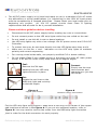
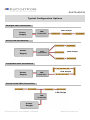
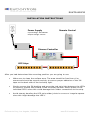
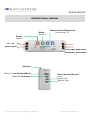
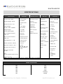
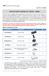
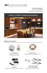
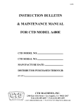
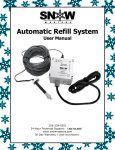
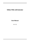
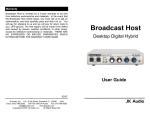
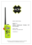
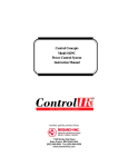
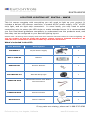
EUKT04-WW30 LED STRIP LIGHTING KIT EUKT04 – WW30 This kit comes complete with everything you will need to light up your project. It includes a deluxe LED dimmer controller, a mated AC/DC power supply, 16’4” of LED strip light, and six light strip connectors. In some cases, you may need to splice connecting wire to power the LED strips or make extended turns. It is recommended you first read these guidelines completely to understand how the products work, and how they can be configured to your desired lighting layout. Please note: All wiring must comply with local and national electrical codes for Class II lighting. If you are unclear on how to install this product, please contact a licensed electrician. All 120V AC main connections should be made by a licensed electrician. What’s included in the KIT: Part Number Description Item QTY EUPS06012 AC/DC Power Supply 1 DU3-11500-RF Dimmer 1 EUACRE-001 Dimmer Remote 1 EULSW0230-5.0 WW LED Strip Light 1 EUAECON-W10 Wired Interconnect with End to End connectors 4 EUABCON-W10 Butt Connectors 2 MKT04-Rev1 Owner’s Manual 1 If any parts are missing, please call 1-888-535-9580 EuControls Corp, Los Angeles, California www.EuControls.com EUKT04-WW30 The AC/DC power supply is UL listed and ready to use in a standard 120V AC outlet. Any alterations or wiring modifications (i.e. hardwiring) to the 120V AC input power must be completed by a licensed electrician. Please check your local codes prior to beginning any project. All 12V DC output circuits meet Class II lighting requirements and are safe for do it yourself installation. Please read these guidelines before installing: Disconnect the AC/DC power supply before making any cuts or connections. Do not connect power to the LED strip lights while they are coiled on the reel. Do not install or use this kit in wet or damp locations. Use LED strip lights only with a low voltage 12V DC power source and 5-24V DC Controller. To protect the eyes, do not stare directly into the LED lights when they are lit. Make sure to use the + and - indicators on the LED strip lights to maintain polarity and correct sequencing. For running wires inside walls, use properly certified CL2 or better cabling. Do not install Class 2 low voltage wiring in the same runs with AC main power wiring. If AC and DC wires cross, keep them at 90-degree angles. Peel: Remove the 3M tape backing from the LED strip lights and stick in place. Connect: Simply use the wire interconnects and connectors to join the LED strips. Cut: Locate the cut lines on the RGB strip light and cut strip to desired length. Cutting: Figure A Copper pad location Figure B Soldered copper pad location Cut the LED strip light using scissors. Make sure to cut strip in the center of the copper pad locations as shown in the Figure A. If you cut at a soldered location, refer to Figure B. You may need to remove the solder from the RGB strip light connection joint in order for the butt connectors to work properly. EuControls Corp, Los Angeles, California www.EuControls.com EUKT04-WW30 Connecting: Figure 1 Figure 3 Insert the LED strip into the channel sides and under contact tabs. Carefully slide the LED tape into the connector so that copper pads on the LED strip are positioned underneath the connector contacts. Figure 2 Snap the lid down to close the connector. Perform a test to be sure that the connection is correct and that the LED’s light before proceeding with the final installation. Important: Make sure to keep the correct polarity of -/+ indicators printed on the LED tape light to ensure correct color sequencing. If necessary, the LED wires can be extended using 4-conductor 22-18 AWG wire. But the shorter the length of wire added or the larger the wire gauge, the less chance for voltage drop which would allow for higher LED brightness. Please consult your electrician if you are unclear about your connections. Planning: EUKT04 Kit is designed for indirect lighting applications. The light from the LED strip should not be directly visable. Every design is unique and the lighting effects depend on your personal preference. The installation location, surfaces, wall colors, mounting angle, and objects can all affect the lighting appearance. Before installing this LED lighting kit please consider the following: Location of the power supply and the dimmer Controller. LED Lighting ON and OFF plan. The layout the configuration you will be using. Wire connections to your LED strips. EuControls Corp, Los Angeles, California www.EuControls.com EUKT04-WW30 Typical Configuration Options Straight LED Connection Power Supply LED Controller LED Strips Array LED Connection Power Supply LED Controller LED Strips Loop Back LED Connection Power Supply LED Controller LED Strips Center Feed LED Connection LED Strips LED Controller Power Supply EuControls Corp, Los Angeles, California www.EuControls.com EUKT04-WW30 INSTALLATION INSTRUCTIONS Power Supply Remote Control Input Voltage: 100-240VAC Output Voltage: 12V DC Dimmer Controller LED Strips After you had determined the mounting position you are going to use. Make sure to clean the surface area. The area should be free from oil or waxes and should be smooth and dry to ensure proper adhesion of the 3M tape on the back side of the Led strip light. Gently remove the 3M backing and press the Led strip light between the LED’s to securely contact the surface of the mounting surface. Never press on the individual LED’s since this could damage their solder connections to the strip. Avoid sharply bending the LED strip solder joints in curves or irregular spaces since this might damage the LED’s. EuControls Corp, Los Angeles, California www.EuControls.com EUKT04-WW30 OPERATIONAL MANUAL Mode function Select desired Brightness: By pressing + or - Power: ON/OFF DC 12V (+) power input (-) LED Light Strip wires and power connection Antenna Press (A) for Desired Mode Press (B) for Pause EuControls Corp, Los Angeles, California Select desired Speed: Press ( C ) for Fast ( D ) for Slow www.EuControls.com EUKT04-WW30 SPECIFICATIONS Dimmer Controller Power Supply Output Power: 60W Input Voltage: 12/24VDC Output Voltage: 12V DC Output Power: 12V Output Current: 0 - 5A Input Voltage: AC 100 - 240V 50/60Hz 12V: 180W; 24V: 360W Range Voltage: AC 90 -264V 47/63Hz 0 to 100% Brightness Remote Control LED Tape Connector RF remote control 5050 smd Use for: AWG 22# Distance: up to 30 meters. 30 LED/meter LED strip thickness: 0.3mm Speed and brightness adjustments 12V DC Maximum Operation temp: -20° ~ 50 °C Pause Function Current: 5A AC,DC Voltage: 12-24V DC Non-waterproof Battery: Alkaline 23A 12V 256 level Grayscale Over-current Protection: 120% min ON/OFF Function with RF Remote Storage Temp: -30℃ ~ 80℃ Voltage Resistance: 1500V AC/min Load Regulation: +/- 5% Single Channel Max 15A per channel Power per meter: 14.4watt Contact Resistor: 30m max Color: Warm White 1000m min Ripple and Noise: 100mV Operation Temp: 0 - 40 °C Storage Temp: -20 -85 °C Built-in 0%,25%,50%,75%, 100% brightness mode View Angle: 120 degrees Operation temp: 40° ~ 105 °C Over-voltage Protection: 120% min Housing: PA6 IP20 Tooth Slice: double Tin Operation Humidity: 5 - 95% Size: 12.88mm x 15.48mm X 3.3mm Size: (L)119 x (W)52 x (H)31.7 (mm) Safety: UL Listed Cord: Input cable wire stripped and tinned. 18 AWG black power cord 120VAC. MODE SELECTION M1 M2 M3 M4 M5 M6 M7 EuControls Corp, Los Angeles, California 0% 25% 50% 75% 100% Flashing Fading www.EuControls.com EUKT04-WW30 Standard Product Warranty PRODUCT WARRANTY: EuControls warrants that at the time of shipment, the standard products manufactured by EuControls, and sold hereunder, will be free from defects in material and workmanship for a period of three years from the date of shipment. Warranty Adjustment: Buyer shall notify EuControls immediately if any defect within the warranty period should appear. EuControls agrees to repair or furnish a replacement for, but not install, any product which within three (3) years from the date of shipment by EuControls, shall upon examination by EuControls, prove defective within the above warranty period. No product will be accepted for return or replacement without written authorization of EuControls. Upon such authorization, and in accordance with instructions by EuControls, the product will be returned shipping charge prepaid by Buyer. Replacements made under this warranty will be shipped prepaid by Seller. Exclusions from Warranty: This warranty does not extend to any products manufactured by EuControls which has been subjected to misuse, neglect, accident, improper installation or use in violation of instructions furnished by EuControls. This warranty does not extend to, or apply to, any unit which has been repaired or altered other than at EuControls’ factory, or by persons not expressly approved by EuControls. Components purchased or made by Buyer from any supplier other than EuControls shall bear only the warranty given by the manufacturer of that product, and EuControls assumes no responsibility for the interface of its product with any other product, and such responsibility shall remain with Buyer for interface, functionality, and intended use. Notice: The foregoing warranty is in lieu of and excludes all other expressed or implied warranties of merchantability or fitness for use or otherwise. EuControls Corporation 19210 S. Vermont Ave, Ste 310 Gardena, CA 90248 United States Toll-free sales hotline: +1 (888) 535-9580 Tel: +1 (310) 643-5700 Fax: +1 (310) 643-5688 EuControls Corp, Los Angeles, California www.EuControls.com