1
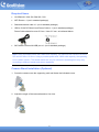
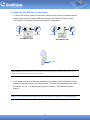
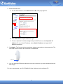
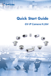
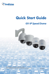
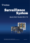
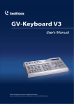
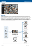
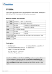
Surveillance Flexibility with GeoVision Wireless Cube IP Cameras Article ID: GV15-13-03-07-l Release Date: 03/07/2013 Applied to GV-CBW120 / 220 GV-CAW120 / 220 Introduction Taking advantage of the light weight, compact size and WiFi feature, GeoVision Wireless Cube IP Cameras are extremely flexible in their applications. With a portable power and wireless connectivity, no other installation is required. You can adjust the camera in any angle and place it in any indoor location within the WiFi range. The cameras are ideal for people with the need to change the monitored location without having to install more than one camera. For instance, a busy working-at-home mother can work in the study, and place the camera in the living room to keep an eye on her kids when they play. When her kids go to their room, she can move the camera to the kids’ room to continue checking up on the kids. Portable Power 1 Required Items GV-CBW120 / 220, GV-CAW120 / 220 WiFi Router x 1 (not in standard package) Standard network cable x 1 (not in standard package) USB to 5 Volt DC Barrel Jack Power Cable x 1 (not in standard package) Power Cable should be outer 5.5 mm / inner 2.5 mm, as indicated below. 2A Portable Power with USB port x 1 (not in standard package) Note: Using a portable power with 18000 mAh capacity, GV-CAW120 can record to its micro SD card for about 12 hours. Using a portable power with 12000 mAh capacity, the operating hour is about 8 hours. The tested results are only for reference. Operating hour may vary according to different brands and power capacities. Camera Stand Installation (Optional) 1. Screw the camera onto the supporting rack and fasten the indicated screw. 2. Adjust the angle of the camera based on live view. 2 Configuring the Wireless Connection 1. To set up the wireless LAN for the first time, power on and connect a standard network cable to the camera. The status LED will be orange (GV-CBW120 / 220) or green (GV-CAW120 / 220) when the camera is ready for configuration. LAN / PoE Power Port LAN / PoE Power Port GV-CBW120 / 220 GV-CAW120 / 220 Status LED IMPORTANT: Before power-on, make sure the power adapter is within the power value range indicated at the camera’s back panel. 2. An IP address will be automatically assigned to the camera. Use GV IP Device Utility to search the camera and log in the Web interface. The default ID and password is admin. For details, see 14.1.1 Checking the Dynamic IP Address, GV-IPCAMH264 User’s Manual. Note: If your router does not support DHCP, the default IP address will be 192.168.0.10. 3 3. Configure the wireless settings. A. On the Web interface, select Network, select Wireless and Client Mode. This dialog box appears. B. Type the Network Name (SSID) or click the Access Point Survey button to search and select for the available Access Points/wireless stations. C. Select Ad-Hoc or Infrastructure for the Network type. D. Select the Authentication Type using the drop-down list. You can also obtain this information by clicking the Access Point Survey button. E. Type the WPA-PSK Pre-shared Key or WEP depending on the encryption setting for the Access Point. F. Click Apply to save the configuration. Note: 1. Your encryption settings must match those used by the Access Points or wireless stations with which you want to associate. 2. When Ad Hoc is used, only WEP encryption is supported. 3. When you lose the wireless access, you can still access the unit by connecting it to a LAN and using the GV IP Device Utility to search for the device. 4. For detailed information on configuring the wireless LAN, see 16.7.2 Wireless Client Mode, GV-IPCAMH264 User’s Manual. 4 4. Enable wireless LAN. A. On the Web interface, select Network and LAN. This page appears. B. Select Wireless for Optional Network Type. C. To use a dynamic IP address assigned by the DHCP server, select Dynamic IP address. To use a fixed IP address, select Static IP address and type the IP address information. 5. Click Apply. The Camera will start creating a wireless connection to the access point. The LAN LED turns blue when the connection is established. LAN LED 6. You can unplug the Ethernet cable and move the camera to any indoor location within the WiFi range. For more setup details, see GV-IPCAMH264 User’s Manual on the software CD. 5