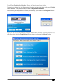
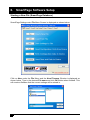
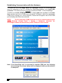
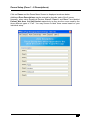
1
SPMS SmartPage Messaging System INSTALLATION AND USER MANUAL SmartPage Installation and User Manual V1.6 1. Contents 1. Contents...........................................................1 2. Overview.......................................................... 2 Introduction.......................................................................................................... 2 Equipment List.....................................................................................................2 Programming Software...................................................................................... 2 Power Supply.......................................................................................................2 3. Hardware Setup............................................. 3 Basic System Configuration.............................................................................. 3 Setting up the Ports.................................................................... 3 PCB Layout..........................................................................................................4 Paging Transmitter Wiring Diagram.................................................................5 Transmitter Pin Outs.................................................................. 5 Setting up the Transmitter in SmartPage Software.............. 5 Setting up the Hyper Terminal for Data Logging........................................... 5 4. SmartPage Software Installation.............. 6 SmartPage Software Installation...................................................................... 6 5. Registering SmartPage Software............. 8 Registering SmartPage Software..................................................................... 8 6. SmartPage Software Setup...................... 10 Starting a New File (SmartPage Database)................................................. 10 Loading and Saving Files (SmartPage Database)...................................... 11 Establishing Communication with the Hardware......................................... 12 Read, Write and Time/Date functions (SmartPage Database)................. 13 Groups Setup (Create/Edit Groups and Group Names).............................14 Resets Setup (Reset Pagers)......................................................................... 15 Date Display Setup (Sends Date to Cap Codes at Midnight)....................16 Zones Setup (Zone 1 - 8 Descriptions)......................................................... 17 Options Setup (Alert Cadence, Receiver Settings & Special Options).... 18 Clients Setup (New / Edit Clients)..................................................................19 Clients Setup (Search Clients)....................................................................... 20 Clients Setup (Print Clients)............................................................................21 SmartPage Installation and User Manual v1.6 1 2. Overview Introduction The SmartPage messaging unit is a compact, stand alone direct paging and messaging solution. Once programmed, the SmartPage unit can process and page alarms from any two of SmartLink’s Telephone based, Wireless or Hardwired systems. The unit also incorporates a printer port for direct connection to most serial printers or any computer running Hyper Terminal for the purpose of event logging. Other powerful features of the SmartPage system include Grouping of pagers, setting up of Escalations, and Repeat paging with numerous CAP codes. Equipment List A SmartPage Messaging System consists of the following equipment: SmartPage Unit (Note: POCSAG transmitter not included) Windows Programming Software Programming Cable (Null Modem DB9 to DB9 Female) 12V DC 2Amp Regulated Plug Pack Installation and User Manual Programming Software The SmartPage unit needs to be configured with the Software that is provided. The software is an integral part of the SmartPage System and enables the user to change settings and Maintain the list of clients that are in the SmartPage unit. The software will need to be installed on a WIN2000 or WIN XP system. Once installed it will need to be registered with SmartLink to become operational. The registration process will involve contacting SmartLink and obtaining a Registration Number which will activate the Software. Power Supply The SmartPage Messaging system comes with a 12Volt DC 2Amp Regulated plug pack. The quiescent current drawn by the SmartPage unit is approximately 100mA. 2 SmartPage Installation and User Manual v1.6 3. Hardware Setup Basic System Configuration SmartLite Remote LED-DEC Display Bravo Pager Genie Pager To Paging Transmitter Power Supply (12V DC) SmartPage Unit Serial Printer OR Hyper-Terminal SmartLine (9600 baud) SCU2 (1200 baud) SmartWire MKII (9600 baud) Wireless Nurse Call System Line Receiver Hard Wired Nurse Call System Setting up the Ports Refer to Options Setup menu under Software Settings. SmartPage Installation and User Manual v1.6 3 PCB Layout Top View of SmartPage Printed Circuit Board 1. 2. 3. 4. 5. 6. 7. 8. 9. 10. 11. 12. Port 1 / Program 1. 2. 3. 4. 5. 6. 7. 8. 9. 10. 11. 12. 4 Port 2 Printer / HyperTerminal +12V DC supply (quiescent current drawn is approx 100mA) Data connector for POCSAG transmitter PTT connector for POCSAG transmitter Ground connection for power supply and POCSAG transmitter Buzzer Power ON LED Activity LED Buzzer Enable jumper (speaker is ON when jumper present) Clock Adjustment + Button Clock Adjustment - Button Power Reset Button 3V Lithium Battery (CR2032) to backup Date and Time WARNING: Remove Battery TAB to Enable Clock Backup. SmartPage Installation and User Manual v1.6 Paging Transmitter Wiring Diagram SmartPage provides the ability to send messages to local area pagers using a POCSAG transmitter. A transmitter provided by SmartLink may be plugged directly to the DB25 Male connector attached to the SmartPage unit. Note: If using any other brand of POCSAG transmitter, the connection can be made directly to the SmartPage via the terminal block found on the PCB (see PCB layout). Transmitter Pin Outs SmartPage Unit DB25 Male MAXON Intelpage 5W PT400 PT500 Transmitter Pins Connector DB9 RJ45 DB15 DB9 Data (POCSAG) PTT (Push to Talk) Ground 4 (Orange) 20 (Blue) 9 3 6 4 13 5 5 3 7 (White/Blue) 4 5 1 6 Wa rni ng: As the transmitter is a source of considerable RF energy, you should ensure that it is not located within 3 meters of any electronics equipment to prevent interference. Setting up the Transmitter in SmartPage Software Refer to Options Setup menu under SmartPage Software Setup. Setting up the Hyper Terminal for Data Logging COM Port Properties Screen as shown below. Baud rate: 1200 Data bits: 8 Parity: None Stop bits: 1 Flow Control: Hardware SmartPage Installation and User Manual v1.6 5 4. SmartPage Software Installation SmartPage Software Installation Note: The SmartPage Software will only operate on a WIN2000 or WIN XP system. Insert the SmartPage Software Installation CD in the CD-ROM drive. Make sure that no other programs are running. The auto-run screen will startup as shown below. Click the OK Button to continue. NOTE: If the auto-run screen does not start up, browse the contents of the CD-ROM drive containing the SmartPage Installation CD using Windows Explorer or My Computer and double click setup.exe Click on the PC Icon Button as shown below to continue. 6 SmartPage Installation and User Manual v1.6 Click the Continue Button as shown below to continue. Click the OK Button as shown below to complete the SmartPage Software installation. NOTE: Restart the PC to let the changes take effect. SmartPage Installation and User Manual v1.6 7 5. Registering SmartPage Software Registering SmartPage Software NOTE: Once the SmartPage Software is installed, you must contact your dealer for the Registration Number. None of the features of the software are operational until the Registration number has been entered. To begin the registration process, click on the SmartPage Registration Button as shown below. 8 SmartPage Installation and User Manual v1.6 SmartPage Registration Number Screen will startup as shown below. Contact your dealer for the Registration Number and provide them with your 12 digit Serial Number. They will provide you with a Registration number. After entering the Registration number provided by your dealer Click Register Button. Now you are in the SmartPage Software Main Menu Screen as shown below. You will also notice that the Registration Button has now changed to About Button. SmartPage Installation and User Manual v1.6 9 6. SmartPage Software Setup Starting a New File (SmartPage Database) SmartPage Settings main File Menu Screen is displayed as shown below. Click on New under the File Menu and the New Filename Window is displayed as shown below. Type in the desired File name and click OK Button when finished. This will create a filename that the current settings will be stored in. 10 SmartPage Installation and User Manual v1.6 Loading and Saving Files (SmartPage Database) Click on Load under the File Menu and the Load Settings Window is displayed as shown below. Select the desired file from the right window and click the Open Button. The settings stored in the file will be uploaded into the program. To save any changes that have been made to a file that has been newly created or loaded simply click on the Save Button under the File Menu to save the settings to the file. Once the file is saved a confirmation window will be displayed, as shown below. Click the OK Button to continue. SmartPage Installation and User Manual v1.6 11 Establishing Communication with the Hardware To enable the use of the Read, Write and Time/Date functions the SmartPage unit must be connected to the PC running the SmartPage software via a serial DB9 connector. The serial connector must be connected to PORT 1 of the SmartPage. To select an available COM Port on the PC, simply right click anywhere on the blue Menu window and a list of COM ports will appear. Proceed to select the appropriate COM Port by clicking on it. Once selected, a small tick will appear next to the COM port indicating that it has been selected. NOTE: The PC must have COM1 listed as one of its communications ports under Windows (Control Panel -> System -> Hardware), otherwise the SmartPage software will not allow any other COM port to be selected. Note: If the SmartPage unit is connected to another COM port the following error message (as shown below) will be displayed when synchronisation is attempted. 12 SmartPage Installation and User Manual v1.6 Read, Write and Time/Date functions (SmartPage Database) Once the connection is established, click on the Read Button under the File Menu. The following window will appear to confirm that communication has been established and reading is in progress. Once the Read function is completed the following message will be displayed as shown below. The Write function operates in a similar fashion. To send the current Date and Time to the SmartPage unit click on the Time/Date Button under the File Menu. A progress bar will be displayed, followed by a “Transfer Complete” message as shown below. SmartPage Installation and User Manual v1.6 13 Groups Setup (Create/Edit Groups and Group Names) Click on Groups and the Groups Menu Screen is displayed as shown below. To create a new Group, simply select or enter a Group Number (between 1 and 16). Enter a Group Name (up to 128 characters). For example: Staff Pager & Remote Display. Select the Escalation from the pull down button. Enter the number of Repeat Count (between 0 and 255). Enter the number of Repeat Delay (between 20 and 2400 in Seconds). Enter the 7 digits Cap Code for each Group (up to 32 Cap Codes and must be Less than 2097152). For example: Staff Pager 0050808 and Remote Display 0123464 Cap Codes. 14 SmartPage Installation and User Manual v1.6 Resets Setup (Reset Pagers) The Resets and Date Display features are included mainly to cater for the Remote Display Wireless Decoders, otherwise known as Wireless Displays. Whenever the SmartPage unit is reset the CAP codes listed under the “Reset” menu are also reset. The CAP codes listed under the “Date Display” menu are sent the current date and time. Click on Resets and the Resets Menu Screen is displayed as shown below. Enter the 7 digits Cap Code (up to 32 Cap Codes). For example: Remote Display 0123464 as the Cap Code. The Remote Display Wireless Decoder unit will be reset when the SmartPage Master unit is RESET. SmartPage Installation and User Manual v1.6 15 Date Display Setup (Sends Date to Cap Codes at Midnight) The Resets and Date Display features are included mainly to cater for the Remote Display Wireless Decoders, otherwise known as Wireless Displays. Whenever the SmartPage unit is reset the CAP codes listed under the “Reset” menu are also reset. The CAP codes listed under the “Date Display” menu are sent the current date and time. Click on Date Display and the Date Display Menu Screen is displayed as shown below. Enter the 7 digits Cap Code (up to 32 Cap Codes). For example: Enter 0123464 as the Cap Code for the Remote Display. At Midnight, the SmartPage Master unit will send the Date to the Remote Display Wireless Decoder (0123464). 16 SmartPage Installation and User Manual v1.6 Zones Setup (Zone 1 - 8 Descriptions) Click on Zones and the Zones Menu Screen is displayed as shown below. Additional Zone Descriptions may be entered to describe each of the 8 zones. Normally, when using SmartLink Devices, Zone 5, Zone 6, and Zone 7 are labelled Patient, Wet Area, and Staff Assist respectively as they are the zones used by the three different types of “Call”. You may choose to label these zones based on your individual setup. SmartPage Installation and User Manual v1.6 17 Options Setup (Alert Cadence, Receiver Settings & Special Options) Click on Options and the Options Menu Screen is displayed as shown below. Select the Alert Cadence or leave as default. Select the appropriate Baud Rate Settings. The SmartPage receiver ports (Port 1 and Port 2) can handle Ademco "High Speed" format for a variety of SmartLink products and systems including SmartLink Medi-Call Dialler Units (Utilising SCU2 Receiver). This SmartPage Receiver Port allows receipt of information from various SmartLink products where it is automatically linked to Clients and paged onto the relevant pagers. NOTE: SmartLine Wireless set to 9600 Baud Rate SmartWire MKII Nurse Call set to 9600 Baud Rate SCU2 Receiver set to 1200 Baud Rate Select the appropriate Special Options. For the transmitter to function, the “Invert DATA” and “Invert PTT” settings will have to be checked with the manufacturer’s specifications. If using a PT400 or PT500 transmitters, both boxes will be ticked. If using a Maxon transmitter, only “Invert PTT” box will be ticked. 18 SmartPage Installation and User Manual v1.6 Clients Setup (New / Edit Clients) Click on Clients and the Clients Menu Screen is displayed as shown below. To create a New Client, simply enter a Client Code (4 Digits). Enter a Client Name (up to 80 characters). For example: Unit 001 – Mrs Brown 95960770 Select the Group Names from the pull down button for each Emergency, Call, Nurse Present and Service. Click on Save Client when finished. NOTE: The maximum number of Clients available are 1900. The Client Code may be any 4 digit combination ranging from 0001 to 9999. SmartPage Installation and User Manual v1.6 19 Clients Setup (Search Clients) Click on Clients, then Search Clients and the Search Client Screen is displayed as shown below. Enter All or Part of the Clients Name or just click on Search as shown above. 20 SmartPage Installation and User Manual v1.6 Clients Setup (Print Clients) Click on Clients, Search Clients then Print and the Print Screen is displayed as shown below. The order in which the Client List is Printed may be changed by selecting: By Client Name By Client Number Select the Available Printer you wish to print and click on the Print Button. “A division of NESS CORPORATION PTY LTD” © Copyright SmartLink November 2015 Unit 4/56 Norcal Rd, Nunawading VIC 3131 Australia Tel: +61 3 9875 6400 Fax: +61 3 9875 6422 Email: [email protected] Website: www.smartlink.com.au To the best of our knowledge, the information contained in this manual is correct at the time of print. SmartLink International “A division of NESS CORPORATION PTY LTD” reserves the right to make changes to the features and specifications at any time without prior notice in the course of product development. SmartPage Installation and User Manual v1.6 21