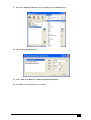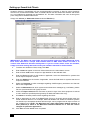
1
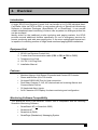
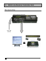
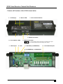
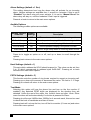
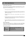
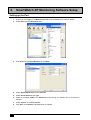
SCU2
Line Receiver Control Unit
INSTALLATION
MANUAL
SCU2 Line Receiver Card Installation Manual v2.3.doc
1. Contents
1. Contents........................................................................................1
2. Overview .......................................................................................2
Introduction ..................................................................................................2
Equipment List .............................................................................................2
Features.......................................................................................................2
Monitoring Software Compatibility ...............................................................2
3. SCU2 Line Receiver Controller Unit ...........................................3
Basic System Setup.....................................................................................3
SCU2 Line Receiver Control Unit Features .................................................4
1. LCD Display.......................................................................................5
2. Status LEDs.......................................................................................6
3. User Interface Buttons .......................................................................6
4. Line In (PSTN / PBX) Connection......................................................6
5. RS485 Connection (Host Communication) ........................................6
6. RS232 Connection (Host Communication) ........................................6
7. 12V DC Input .....................................................................................6
8. Clear ..................................................................................................7
9. Fail/Relay 2 (COM/NO/NC) Relay Output..........................................7
10. Alarm/Relay 1 (COM/NO/NC) Relay Output ......................................7
11. 32 Hardwired Alarm Inputs (fixed Client Account x001 to x032) ........7
4. Menu Options ...............................................................................7
View Buffer ..................................................................................................8
HW Client Code (default = 9000) .................................................................8
Input Settings...............................................................................................8
Alarm Settings (default = 1 Sec) ..................................................................9
Audible Options ...........................................................................................9
Host Settings (default = 1) ...........................................................................9
PSTN Settings (default = 3) .........................................................................9
Test Mode....................................................................................................9
5. Other Specifications ..................................................................10
System States: Ready / Busy ....................................................................10
Host Communication .................................................................................10
Physical Characteristics.............................................................................10
6. SmartWatch XP Monitoring Software Setup............................11
Setting up the Port .....................................................................................11
Setting up SmartLink Clients......................................................................13
1
SCU2 Line Receiver Card Installation Manual v2.3.doc
2. Overview
Introduction
A single SCU2 Line Receiver Control Unit can handle up to 10,000 individual MediCall Dialler Units via PSTN or PBX. In conjunction with any of SmartLink's Monitoring
Software or Hardware Packages (SmartWatch XP or SmartPage), it can provide
reliable telephone-based monitoring of alarm calls anywhere an analogue phone line
can be accessed.
Ideally suited for the traditional on-site monitoring and paging markets, the SCU2
provides several additional facilities specifically for use in emergency services for
remote monitoring and wide area paging also. In the more sophisticated scenarios it
is capable of controlling medium to large-sized monitored paging/SMS installations.
Equipment List
1.
2.
3.
4.
5.
SCU2 Line Receiver Control Unit
2 metre Host Communication cable (DB9 to DB9 or DB9 to DB25)
Telephone Line Cord
12V DC 1.5A Plug Pack
Installation Manual
Features
•
•
•
•
•
•
Monitors Ademco High Speed, Expanded and Contact ID Protocols.
Stores and Buffers up to 100 events.
On-board RS232/485 Port for Host connection.
Dual Relay Outputs (C, NO, NC) that activate on Incoming Alarms and
Communication Failure.
32 Hardwired Alarm Inputs.
2x16 Character LCD Display for alarm monitoring and configuration.
Monitoring Software Compatibility
The SmartLink SCU2 Line Receiver Control Unit is compatible with the following
SmartLink Monitoring Software:
•
•
•
•
SmartWatch XP (or SmartLink 2002)
SmartLink NT
SmartLink-4 (DOS)
SmartPage (Standalone) Messaging System
SCU2 Line Receiver Card Installation Manual v2.3.doc
2
3. SCU2 Line Receiver Controller Unit
Basic System Setup
SCU2 Line Receiver Control Unit
PSTN / PBX
(Line In)
OR
SmartLink Monitoring Software
3
SmartPage Messaging System
SCU2 Line Receiver Card Installation Manual v2.3.doc
SCU2 Line Receiver Control Unit Features
Features & Functions of the SCU2 shown below:
1. LCD Display
2. Status LEDS
3. User Interface Buttons
6. RS232 Connection
4. Line In (PSTN / PBX)
5. RS485 Connection
B A Gnd
7. 12VDC Input
8. Clear
A: Non-inverting receiver input and non-inverting driver output
B: Inverting receiver input and inverting driver output
9. FAIL/Relay 2 (COM/NO/NC)
11. 32 Hardwired Inputs
10. ALARM/Relay 1 (COM/NO/NC)
SCU2 Line Receiver Card Installation Manual v2.3.doc
4
1. LCD Display
During normal operation, the 2x16 character LCD Display will show “SmartLink
SCU2, System Ready”. During an incoming call the display will read “Incoming Call,
Ring x/X” (where x is the detected rings and X is the number of rings before the unit
picks up the line). Once the line is picked up the display will show the incoming Data
Strings. In addition, the LCD Display may also be used to view the log buffer. This
can be accessed by going into the menu options and selecting “View Buffer”.
In the event of an error, the unit will display the following messages:
•
“Memory Buffer Full”
When the Log Buffer is full (i.e. system has stored 100 calls and has not sent any
to the Host), the system will immediately display “Warning!, Buffer Full” and will
reject any incoming calls. If under the audible options menu “Buffer Full Beep” is
set to ON, the system will beep continuously (1 beep/sec). Immediately upon
clearing the buffer the error message and audible beeping will return to their
normal state.
•
“PSTN Line Failure”
When the system detects PSTN Line failure, after approx 2 min, it will display
“Warning! PSTN, Line Failure”, and will activate Relay 2. If under the audible
options menu “Line Fail Beep” is ON, the system will beep continuously (1
beep/sec). Immediately upon restoral of the PSTN Line, the Error message,
audible beeping and Fail/Relay 2 will return to their normal state.
•
“Host Communication Failure”
When the system detects Host Communication failure, after approx 1 min, it will
display “Warning! Host, Communications Failure”, and will activate Relay2. If
under the audible options menu “Host Fail Beep” is ON, then system will beep
continuously (1 beep/sec), and Relay 2 will be activated. Immediately upon
restoral of the Host Communication Line, the Error message, audible beeping and
Fail/Relay 2 will return to their normal state.
Note that if the SCU2 is powered up with no Host Communications or PSTN
connection the unit will immediately (10 sec) display PSTN Line failure and Host
Communications Failure messages. This is intended for diagnostic purposes.
5
SCU2 Line Receiver Card Installation Manual v2.3.doc
2. Status LEDs
•
Power LED (Green LED left of display): Always ON when SCU2 powered.
•
Line LED (Green): ON when “PSTN ring settings” match the detected rings
and remains ON until the unit receives a complete valid data string,
otherwise in the case of data error it will go OFF in next 500ms.
•
Rx LED (Green): Intermittently FLASHES when Address/ENQ received
from the Host Computer (Monitoring Software or SmartPage Messaging
System).
•
Tx LED (Green): Intermittently FLASHES when unit transmits an ACK
character to the Host Computer (Monitoring Software or SmartPage
Messaging System).
•
Alarm / Relay 1 LED (Green): Controlled by “Alarm Settings” option. When
enabled, and whenever an Alarm (except Manual Test, Auto Test Calls or
any Restores) is detected in PSTN data string, or 32 Hardwired Inputs, this
LED will turn ON for the Time set under ”Alarm Relay Time”.
•
Fail / Relay 2 LED (Green): Normally OFF. When any of the two errors
occur (PSTN Line Failure or Host Communication Failure), this LED will
turn ON and remain ON until the errors are restored.
3. User Interface Buttons
•
Exit / Back Button: Exit from the Main Menu or any of the Sub Menus.
•
Down Button: Scroll Down the Main Menu or any of the Sub Menus.
•
Up Button: Scroll Up the Main Menu or any of the Sub Menus.
•
Select / Toggle Button: Select/Toggle Settings.
4. Line In (PSTN / PBX) Connection
PSTN / PBX Line connection.
5. RS485 Connection (Host Communication)
Enables Multiple SCU2 Line Receiver Control Units to be connected on a single
RS485 bus to SmartLink Monitoring PC (refer SmartLink International Pty Ltd).
6. RS232 Connection (Host Communication)
Enables connection to SmartLink Monitoring PC or SmartPage via Serial Cable.
7. 12V DC Input
The SCU2 Line Receiver Control Unit requires 12V DC “Regulated” 500mA
power source.
SCU2 Line Receiver Card Installation Manual v2.3.doc
6
8. Clear
Shorting the “Clear” terminal to Ground will clear the “Alarm / Relay 1” Output”.
However this will only be possible if the “Alarm settings” option is set “Manual
reset”.
9. Fail/Relay 2 (COM/NO/NC) Relay Output
Any of the three system errors (Memory Buffer Full, PSTN Line Failure, or
Host Communication Failure), will cause the FAIL relay to latch ON and
remain ON until the errors are restored.
10. Alarm/Relay 1 (COM/NO/NC) Relay Output
Controlled under the “Alarm Settings” option, when enabled, an Alarm (except
Manual Test, Auto Test Calls or any Restores) detected in PSTN data string,
or 32 Hardwired Inputs, will cause this Relay Output to latch ON and stay ON
for the Time set under ”Alarm Relay Time”.
11. 32 Hardwired Alarm Inputs (fixed Client Account x001 to x032)
In addition to the SCU2’s primary purpose of monitoring Alarm calls through a
PSTN / PBX line, the unit is also capable of monitoring up to 32 Hardwired
Alarm Inputs. Each input can be set to Normally Open, Normally Closed, Pulse
or Static depending on the “Input Settings”. The Client Account code is preassigned respectively from x001 to x032 where x is between 0 to 9 depending
on the “HW Client Code” setting.
4. Menu Options
There are 8 Main menu options that may be accessed using the UP and DOWN
scroll buttons. Each option has its own Sub Menu. In order for any changes to take
effect a power reset is recommended.
View Buffer
HW Client Code
Input Settings
Alarm Settings
Audible Options
Host Settings
PSTN Settings
Test mode
Note: During an Incoming call the user cannot access Menu Options.
7
SCU2 Line Receiver Card Installation Manual v2.3.doc
View Buffer
This function displays the buffer stack contents, the stack position is shown on the
left, followed by ‘EMPTY’ or an Ademco string.
Pressing up or down will scroll through the stack locations. Pressing ok or back
will return to the main menu options.
Maximum number of Log Buffers is 100. The contents of the buffer can be cleared
either by resetting the power or by pressing the small push button behind the LCD
Display.
Note that the buffer position marked “NR:” is the next pre-loaded Ademco
response. It is not actually part of the buffer stack, but is displayed here to prevent
the information being hidden.
HW Client Code (default = 9000)
The offset for the Client code can be set from 0xxx to 9xxx under this menu.
Input Settings
Each of the 32 hard wired inputs can be configured with the following options:
Input Settings
Submenu
Default
Settings
Description
Input Enabled
Yes
Press ok to enable or disable this input
Zone
1
Press ok to toggle zone between 1 and 8
Priority
Alarm
Press ok to toggle alarm or emergency priority
Mode
Static Level
Press ok to toggle pulsed or static input
Polarity
N/O
Press ok to toggle N/O or N/C setting
Enable/Disable: Enables or disables the input
Zone 1 or Zone 8: Selects zone 1 or 8 of the Ademco output.
Alarm or Emergency: Selects if the input will generate an Ademco alarm or
emergency event.
Pulsed or Static level: If set to Pulsed, the input will not generate restores, this is
intended for push buttons which can only cause a momentary closing or opening
of the connection. If set to Static, the input will generate an activation and a
restore.
N/O or N/C: Normally Open setting will generate an alarm when the input is
connected, and restore it when the input is disconnected. Normally Closed setting
will generate an alarm when the input is disconnected, and restore it when the
input is re-connected.
Note: Inputs are read every 100mS; therefore a momentary connection should
exist for a minimum of 100mS to guarantee a response.
SCU2 Line Receiver Card Installation Manual v2.3.doc
8
Alarm Settings (default = 1 Sec)
This setting determines how long the alarm relay will activate for an incoming
alarm. Various settings are available from 1 second to 4 minutes. If this is set to
“Disabled” the alarm relay will never activate, if it is set to “Manual Reset” the
alarm relay will stay on, until the hardwired ‘Clear’ input is triggered.
Press ok or back to return to the main menu options.
Audible Options
The following audible options are available:
Audible Options
Submenu
Default
Settings
Description
Line Monitor
OFF
This can be enabled to listen to incoming calls.
Buffer full beep
ON
Sound repeated beeping if the buffer stack gets full.
Host fail beep
ON
Sound repeated beeping if the host fails.
Line fail beep
ON
Sound repeated beeping if the phone line fails.
Alarm beep
ON
Sound a single beep when an incoming alarm occurs.
Press ok to toggle an option on or off, and up or down to scroll through the
options.
Pressing back returns to the main menu options.
Host Settings (default = 1)
This sets which address the SCU2 should respond to. The value can be set from
0 to 15 which corresponds to address bytes 0x20-0x2F. Pressing ok or back
returns to the main menu options.
PSTN Settings (default = 3)
This function sets the number of ring bursts required to accept an incoming call.
Pressing up or down will increment or decrement the value. The limit is 2 - 9 rings.
Pressing ok or back will return to the main menu options.
Test Mode
Selecting this option will loop the phone line and turn on the line monitor (if
enabled). Any detected DTMF digits are displayed for the duration they are
detected. Unlike the rest of the menu, this function times out after 10min. Other
menu functions will exit automatically if no button is pressed for 20sec.
Pressing ok will sound 1400Hz then 2300Hz for 4 seconds each, this can be used
to check the level of handshake and kiss-off tones.
Pressing back will un-loop the line, turn off the line monitor (if it was on) and return
to the main menu options.
9
SCU2 Line Receiver Card Installation Manual v2.3.doc
5. Other Specifications
System States: Ready / Busy
Some of the SCU2’s functionality is dependant on the state the system is in. While
the SCU2 is idle, it will perform all of its functions. While the SCU2 is in the menu, or
taking a call, it will not do the following:
•
Detect rings and answer an incoming call.
•
Remove events from the buffer stack for host responses. (The SCU2 may
respond to the host with one pre-loaded Ademco string, after which it will
respond only with <ACK>.)
•
Change the state of the fault relay, or detect changes in host or line fault
conditions.
•
Activate the alarm relay. The alarm relay can still be cleared manually. If an
incoming alarm occurs during the menu or dial sequence, the alarm relay will
activate when the system returns to idle.
•
Sound any audible alerts. If an incoming alarm occurs during the menu or dial
sequence, the incoming alarm beep will not sound until the system returns to
idle.
Host Communication
System communicates with the host at 1200 Baud rate through the RS232 DB9
connecter. Host communication can be identified by Rx and Tx LEDs. System
responds to host data only if Device Address matches the Host request Address.
Physical Characteristics
Size
Length 310mm, Width 115mm, Height 55mm
Colour
Black Powder coated
Case Material
Zinc coated Steel 1mm
Weight
1.4 kg
SCU2 Line Receiver Card Installation Manual v2.3.doc
10
6. SmartWatch XP Monitoring Software Setup
Setting up the Port
1. Ensure you are logged on as Maintenance User (see SmartWatch XP Help for details).
2. Select Ports from the Interfaces Menu.
3. Click New and type SCU2 Receiver as the Name.
4. Select SmartLink Receiver as the Protocol.
5. Select Direct RS-232 as the Type.
6. Select an available COM for the Serial Port and ensuring your Master Unit is connected to
that port.
7. Select <None> as the Flow control.
8. Click Save, then Refresh and Close when completed.
11
SCU2 Line Receiver Card Installation Manual v2.3.doc
9. Now select SmartLink Receiver and then Ports from the Interfaces Menu.
10. Click/Highlight SCU2 Receiver.
11. Select 1200 as the Baud rate, Data=8, Parity=None & Stop=1.
12. Click Save and then Close when completed.
SCU2 Line Receiver Card Installation Manual v2.3.doc
12
Setting up SmartLink Clients
SmartLink Clients in SmartWatch XP are records describing customer or sites for whom SmartLink
devices such as Medi-Call Diallers Units, SmartWire Nurse Call and SmartLine Wireless Call Points
etc. are installed and registered with SmartWatch XP. The alarm information will come in through the
ports configured as SmartLink Receivers.
Simply click Clients (or SmartLink Clients under the Edit Menu).
IMPORTANT: The Name and Code fields are the minimum required to add a SmartLink Client.
Each Client must have a unique Code between 0001 to 9999. Some Codes are fixed in to
various other SmartLink Products and Systems. If you are unsure which codes are available,
simply increment starting 0001 and consult your hardware manuals for further details.
13
1.
To add a new SmartLink Client, simply click New.
2.
Enter a Name to appear on the main Clients list and on the client alarms screen.
3.
Enter a Client Code as the unique four digit identifier for the selected client.
4.
Enter the Phone number for the location if applicable. Leave this field blank for systems that
do not require telephone number.
5.
Enter the Address for the location if applicable. Leave this field blank for systems that do not
require an Address.
6.
Select the Recipient to which messages regarding Call/Emergency activations and Cancels
will be sent if applicable.
7.
Select the Maintenance to which system and maintenance messages eg. Low Battery, Mains
Fail, etc (see SmartLink Call Types) are sent.
8.
Check the Expect Check–In box and enter a period in days if the client equipment is reuired
to call in within the specified period (primarily for Medi-Call Dialler units only).
9.
Use Notes to annotate pertinent facts regarding this Client.
10.
Enter a description for each of the Zone Fields. Zone (or Channel) names should match the
actual SmartLink Devices. For example, Medi-Call Diallers and SmartLine Wireless Systems
can handle up to 8 separate wireless devices which can be programmed to report on each of
the available zones. NOTE: The Medi-Call Unit’s Red (Help) Button default reporting to
Zone (Channel) 6. Refer to the Medi-Call Installation Manual as to how this can be
changed for particular applications.
11.
Click Save and then Close when completed.
SCU2 Line Receiver Card Installation Manual v2.3.doc
© Copyright SmartLink International Pty Ltd
July 2008
Level 1, 304–308 New Street,
Brighton VIC 3186 AUSTRALIA
Tel: +61 3 9596 0770 Fax: +61 3 9596 8195
Email: [email protected]
Web Site: www.smartlink.com.au
To the best of our knowledge, the information contained in this manual is correct at the time of print. SmartLink
International Pty Ltd reserve the right to make changes to the features and specifications at any time without prior notice
in the course of product development.
SCU2 Line Receiver Card Installation Manual v2.3.doc
14