1
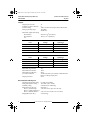
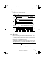
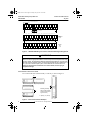
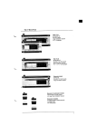
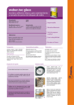
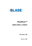
30598-375-01A1 Text Page 1 Saturday, July 26, 1997 10:10 AM
Instruction Bulletin
30598-375-01A1
July 1997
24 VDC 50 VA 16 Relay
Output Base Unit
TBX DSS1625
User’s Manual
30598-375-01A1 Text Page 2 Saturday, July 26, 1997 10:10 AM
WARNING
UNINTENTIONAL EQUIPMENT OPERATION
To avoid improper handling of equipment:
The application of this product requires expertise in the design and
programming of control systems. Only persons with such expertise should be
allowed to program, install, alter, and apply this product.
Failure to observe this instruction can result in death or serious injury.
CAUTION
EQUIPMENT DAMAGE HAZARD
To avoid improper handling of equipment:
1.Never remove this device while power is ON.
2.Do not subject to static discharge. This module contains electronic
components that are very susceptible to damage from electrostatic discharge.
Failure to observe this instruction can result in equipment damage.
SY/MAX, SY/NET, SY/LINK, and SY/MATE are registered trademarks of Square D Company.
PASSPORT and IO/NET are trademarks of Square D Company.
© 1997 Schneider S.A. All rights reserved. This document may not be copied in whole or in part, or
transferred to any other media, without the written permission of Schneider S.A.
Electrical equipment should be serviced only by qualified electrical maintenance personnel. No
responsibility is assumed by Schneider S.A. for any consequences arising out of the use of this
material.
30598-375-01A1 Text Page 3 Saturday, July 26, 1997 10:10 AM
Bulletin No. 30598-375-01A1
July 1997
24 VDC 50VA 16 Relay Output Base Unit
TBX DSS1625
DESCRIPTION
The TBX DSS1625 is a distributed output base unit with sixteen 24 VDC digital relay
outputs. This base unit may be coupled with a compatible communications interface to
form a complete distributed block, which is well suited for the control of discrete field
devices located some distance from a host programmable logic controller (PLC). The
application of distributed I/O blocks saves installation and maintenance cost, compared
to direct wiring of field devices to a centralized I/O system over long distances.
The TBX DSS1625 base unit can be used with either SY/MAX® or Telemecanique
PLCs, through the use of a compatible communications interface (top hat). The
interface mounts directly on the base unit, allowing the PLC to read and write to the
I/O points through a suitable control network. The Class 8030 Type CRM275
Distributed Remote IO/NET™ Interface (DRIO) supports connection to the IO/NET
control network as part of the PASSPORT™ I/O System. The TBX LEP020 and TBX
LEP030 communications interfaces support connection to the FIPIO network. The
TBX CBS010 Expansion Interface allows inexpensive connection of a second TBX
base unit to a single communications top hat.
The TBX DSS1625 base unit supports the following TBX I/O features:
• Sixteen 50 VA Relay Output Points - Suitable for use with discrete field devices
such as solenoids, contactors and pilot lights.
• Output Fallback State Control - Provides point-by-point control over output
states when communication is lost.
• 24 VDC Logic Power Supply - Converts to proper voltage levels for top hat and onboard electronics; may be wired independently from input or output power supplies.
• Removable Field Wiring Terminal Strip - Mounts securely to the base unit
without use of screws or fasteners.
This bulletin contains information on the installation and application of the TBX
DSS1625 base unit with either SY/MAX or Telemecanique PLCs. For information
about programming a SY/MAX PLC for use with the TBX DSS1625 base, refer to the
Class 8030 Type CRM275 (DRIO) instruction bulletin (#30598-380). For information
about programming a Telemecanique PLC for use with the TBX DSS1625 base, refer to
the Telemecanique TBX Distributed I/O Modules manual (TSX DM TBXV52E). Please
read and keep all the appropriate manuals close at hand when using TBX base units.
The top hat receives +24 VDC from the primary base, and converts it to logic power for
the top hat and base. For more information on the DRIO Interface and the Expansion
Interface, refer to bulletins 30598-380 and 30598-371 respectively. You may use the TBX
SUP10 power supply to provide 24 VDC for TBX bases and sensors from an AC source.
SPECIFICATIONS
Base Unit Power
Operating voltage:
24 VDC nominal; 19-30 VDC
Operating current at nominal voltage:
Configuration
Base only
Base with comms interface
Base, interface and expansion base
Nominal
125 mA
195 mA
310 mA
© 1997 Schneider S.A. All Rights Reserved
3
30598-375-01A1 Text Page 4 Saturday, July 26, 1997 10:10 AM
24 VDC 50VA 16 Relay Output Base Unit
TBX DSS1625
Bulletin No. 30598-375-01A1
July 1997
Outputs
Outputs per base unit
Number of output commons
Isolation rating
Voltage operating range
16
8
1500 V rms between outputs and earth terminal
19-30 VDC
24-264 VAC
Maximum output load ratings
DC: Resistive
24 W (0.2 x 10⁶ operations)
DC: Inductive
AC:
10 W (1 x 10⁶ operations)
Load
Resistive
Voltage
Operations
1A
110/220
0.2 x 10⁶
0.5 A
110/220
2 x 10⁶
1A
24/48
0.5 x 10⁶
2A
24
0.2 x 10⁶
Load
Inductive
Voltage
Operations
50 VA
110/220
1 x 10⁶
0.5 A
24/48
1 x 10⁶
10 VA
48/220
1 x 10⁷
1A
24
0.2 x 10⁶
Maximum surge current
Maximum turn ON time
Maximum turn OFF time
I/O status indication
Output protection
30 A
10 ms
20 ms
Visual indication is provided by communications
interface; LED per input point
None
Environmental and Physical
Operating temperature rating
Storage temperature rating
Humidity rating
Dimensions (H x W x D):
Base w/ terminal strip
Base w/comms. interface or
Base w/ CBS010 Interface
Weight (Base unit only)
4
0 to 60°C (32 to 140°F)
-40 to 80°C (-40 to 176°F)
5-95% RH, non-condensing
See Figure 1
3.43 x 9.25 x 2.4 in (87 x 235 x 61 mm)
3.43 x 9.25 x 2.91 in (87 x 235 x 73.9 mm)
2.2 lb (1.0 kg)
© 1997 Schneider S.A. All Rights Reserved
30598-375-01A1 Text Page 5 Saturday, July 26, 1997 10:10 AM
Bulletin No. 30598-375-01A1
July 1997
24 VDC 50VA 16 Relay Output Base Unit
TBX DSS1625
Agency Compliance
0.24
6.1
Complies with UL508, CSA C22-2 requirements, and FM Class I, Division 2
Hazardous Locations approval requirements
3.43
87
2.13
54
1.30
33
0.22
5.6
DIN Rail Center Line
40 Position I/O Terminal Strip
8.27
210
8.74
222
9.25
235
in
Dimensions:
mm
61
1.6
40.6
2.4
Top view with DIN rail mounting dimensions
Side view
Figure 1:
Dimensions
BASE UNIT WIRING
Output devices are wired to the terminal strip on the top of the base unit. Figure 2
shows the terminal strip pin-out for the base unit.
Two terminal strip labels are packaged with the base unit. If you are using the base
unit with a SY/MAX system, use the terminal strip label with I/O numbered from 116; if you have a Telemecanique system, use the terminal strip label with I/O
numbered from 0-15. These are illustrated in Figure 2.
The TBX DSS1625 provides separate terminals for base voltage and control output
voltage. These terminals may be connected to a common 24 VDC supply or may be
sourced by independent supplies (terminals 4 and 1 must be at the same potential).
WARNING
INCORRECT WIRING
The base must be properly grounded before applying power. Equipment MUST be
grounded using the screw provided.
Do not use metallic conduit as a ground conductor.
Failure to observe these instructions can result in death or serious injury.
© 1997 Schneider S.A. All Rights Reserved
5
30598-375-01A1 Text Page 6 Saturday, July 26, 1997 10:10 AM
24 VDC 50VA 16 Relay Output Base Unit
TBX DSS1625
Bulletin No. 30598-375-01A1
July 1997
DC (–)
: Base Line Voltage (24 VDC)
DC (+)
3
1
2
9
7
5
4
6
11
15
13
12
10
8
17
14
21
19
16
18
20
23
25
22
24
27
26
29
28
33
31
30
32
37 39
35
34
36
38
40
AC or DC source
-SV +SV
NC
3
1
2
4
GND
9
O2
6
NC
NC
8
2
1-
M
CO
Figure 2:
O4
13
15
O5
14
16
C2,3
NC
C4,5
O4
11
10
O5
13
12
NC
15
4 NC
21
20
NC C6,7
O7
20
6 NC
M
CO
O9
O10
O11
23
25
27
29
28
33
31
NC
37 39
35
NC
C8,9 NC C10,11 NC C12,13 NC C14,15 NC
O9
O10
O11
O12
23
25
27
29
22
24
26
10
NC
8 NC
7-
M
CO
26
O14 O15
O12 O13
24
21
19
18
O8
22
O8
5-
3-
M
18
17
16
O7
19
O6
14
CO
O6
17
12
O3
9
7
5
O3
11
C0,1 NC
O1
4
O2
10
8
N1
NC
3
2
O1
7
6
N1
VB- VB+
1
O0
5
9-
M
CO
28
30
32
33
31
30
32
-2 NC
36
38
O15 O16
O13 O14
34
36
4 NC
Telemecanique
label
(0-15)
40
SY/MAX
label
(1-16)
NC
38
6 NC GND
-1
13
M
40
37 39
35
-1
11
M
CO
34
15
M
CO
CO
TBX DSS1625 Wiring Connections & Terminal Block Signal Assignments
WARNING
UNINTENTIONAL EQUIPMENT OPERATION
Be sure to use the appropriate SY/MAX or Telemecanique terminal strip label when wiring
inputs or outputs. Two terminal strip labels are packaged with the base unit. If you are using
the base unit with a SY/MAX system, use the terminal strip label with I/O numbered from 116; if you have a Telemecanique system, use the label with I/O numbered from 0-15.
Failure to observe these instructions can result in death, serious injury, or
equipment damage.
MOUNTING INSTRUCTIONS
You can mount the base unit horizontally or vertically, as shown in Figure 3.
①
Mounting horizontally side-by-side
①
①
Mounting vertically
side-by-side (terminal
strips must be toward
right as shown)
① Spacing: 1 in (25 mm)
Mounting horizontally
Figure 3:
6
Base Unit Orientation Examples
© 1997 Schneider S.A. All Rights Reserved
30598-375-01A1 Text Page 7 Saturday, July 26, 1997 10:10 AM
Bulletin No. 30598-375-01A1
July 1997
24 VDC 50VA 16 Relay Output Base Unit
TBX DSS1625
To mount the base unit on a 35-mm DIN rail:
1. Hook the base unit onto the rail as shown
in Figure 4.
2. Press down and toward the DIN rail until
the base unit is secure. (There are two
spring clips in the top of the groove on
the back of the unit.)
To remove the base unit from a DIN rail:
1. Press down on the base unit.
2. Swing the unit outward and lift it off the
rail at the same time as pressing down.
2
NOTE: If the base unit is to be used in a highvibration environment, mounting the unit on a
panel rather than a DIN rail provides more stability.
Use cable ties to secure the communication cable.
1
Figure 4: Mounting and
Removing the
Base Unit
INSTALLATION AND APPLICATION CONSIDERATIONS
NOTE: The base unit is not compatible with the Type CRM270 interface module.
• Base Voltage - The TBX DSS1625 base requires a 24 VDC operating voltage to be
applied between terminals 3 and 1.
• Grounding - The green ground wire must be connected to the ground screw
beside the terminal block.
• Jumper Wire - A #16 AWG wire must be installed between terminals 2 and 40.
• Commons - The TBX DSS1625 base has one common terminal for every two outputs.
• Fusing - The base and control power lines must be externally fused by the user.
• External Wiring - Each terminal accommodates up to two #16 AWG gauge wires.
• Freeze State Control - With TBX Distributed I/O, you may also have the DRIO set
the outputs to a pre-defined state. By defining the output fallback states and
enabling Output Fallback, the DRIO will set the outputs to the fallback state when
communication with the host PLC is lost. When communications are restored, the
outputs return to normal operation. Refer to the Type CRM275 and TSX manuals.
Load 1
O1
Neutral or Return
O1
Control Voltage Supply
Input
Logic
COM 1-2
COM 1-2
Load 2
O2
O2
NC
NC
Simplified schematic for relay output
Figure 5:
(Optional: see “Installation
Considerations)
Method of connecting loads
Simplified Schematic & Output Connections for DSS1625 Base Unit
© 1997 Schneider S.A. All Rights Reserved
7
30598-375-01A1 Text Page 8 Saturday, July 26, 1997 10:10 AM
REGISTER USAGE WITH SY/MAX CLASS 8030 TYPE CRM275 DRIO
MODULE
The TBX DSS1625 base unit supports the assignment of two registers for I/O,
diagnostic and configuration registers. For more information about base unit register
usage, refer to the DRIO instruction bulletin (#30598-380).
This base unit supports output fallback state control (Register 4, bits 5-6; Register 6).
Refer to Chapter 4 of the DRIO instruction bulletin for more information about
register assignments.
WARNING
UNINTENTIONAL EQUIPMENT OPERATION
Do not use reserved registers and bits in PLC programs. Erratic operation may result.
Failure to observe this instruction can result in death, serious injury, or
equipment damage.
Merlin Gerin
30598-375-01A1
Square D
July 1997
Telemecanique
Printed in USA
© 1997 Square D All Rights Reserved
DLC