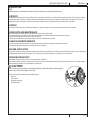
1
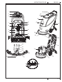
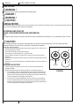
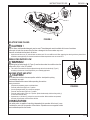
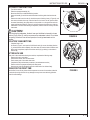
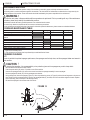
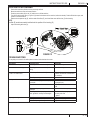
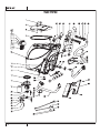
86004 PANTHER 17C VF90042 1/2015 Rev.01 A - ENGLISH INSTRUCTIONS FOR USE TABLE OF CONTENTS Page Introduction............................................................................. A-3 Contents ....................................................................................A-3 Purpose .....................................................................................A-3 Spare Parts and Maintenance ...................................................A-3 Changes and Improvements .....................................................A-3 Machine Application...................................................................A-3 Unpacking/Transport .................................................................A-3 Safety Guides ............................................................................A-4 Technical Data ...........................................................................A-5 Machine Components ...................................................A-6 – A-7 Control Panel ................................................................... A-6 – A-7 Guide For Use ......................................................................... A-8 Before Machine Start-Up ...........................................................A-8 Brush / Pad-Holder Installing and Removal...............................A-8 Squeegee Adjustment ...............................................................A-8 Regulating Water Flow ..............................................................A-9 Machine Start and Stop .............................................................A-9 Machine Operation ..................................................................A-10 Tank Emptying .........................................................................A-10 After Each Use ........................................................................A-11 Using For the First Time ..........................................................A-11 Maintenance and Care ......................................................... A-12 Scheduled Maintenance Table ................................................A-12 Squeegee Cleaning .................................................................A-12 Squeegee Blade Check and Replacement..............................A-13 Brush/ Pad Cleaning................................................................A-13 Water Tank and Float Filter Mesh Cleaning.............................A-14 Solution Filter Cleaning ...........................................................A-15 Troubleshooting ................................................................... A-15 Parts List ...................................................................... B-2 – B-12 A-2 INSTRUCTIONS FOR USE ENGLISH - A INTRODUCTION NOTE Numbers shown in parenthesis correspond with the numbers in the machine exploded view. CONTENTS This manual is intended to provide the operator with the necessary information to use this machine properly and safely. The information includes technical data, safety, operation, storage, maintenance and disposal of the machine. All operators and technicians should study this manual carefully before prior to operating or servicing the machine. Please contact an authorized service provider with any questions. PURPOSE The intention of this manual is to educate the operator and service provider on the proper use and maintenance of this machine. SPARE PARTS AND MAINTENANCE Before servicing the machine park on level ground and unplug cord from the outlet. All necessary operation, maintenance, and repair procedures must be performed by an authorized service provider. Only authorized spare parts and accessories should be used. If service, parts or accessories are needed, please contact an authorized service center. CHANGES AND IMPROVEMENTS We make continuous improvements to our products and reserve the right to change and improve the machines. improvements should be performed by an authorized service provider. MACHINE APPLICATION This scrubber is used in commercial and industrial environments and is suitable for the cleaning of smooth hard floor surfaces. It must be used by qualified operators and in a safe environment. This machine is not to be used outdoors, on carpets, and on coarse floors. UNPACKING/TRANSPORT Please follow carefully the instructions on the package when unpacking. Upon delivery, please inspect the packing and the machine to ensure no damage has been done during transport. If there is any visible damage, please contact the distributor you purchased the machine from. CAUTION ! When unpacking and unloading, or during transportation, please take care to avoid hitting the solution valve. Part A in the figure on the right. Check if the machine is equipped with the following items: 1. Machine 2. User manual 3. Squeegee assembly 4. Brush/pad driver A A-3 A - ENGLISH INSTRUCTIONS FOR USE SAFETY GUIDES The following are special warnings and notices on potential damages (personnel and machine): WARNING ! Machine may only be operated under the guidance of this manual. Only accessories approved by authorized service provider should be used. This machine must be only used by trained & authorized personnel. Children or untrained persons must not use this machine. When working near electrical parts, please do not wear any jewelry. Please take all precautionary measures to avoid hair, jewelry, and loose fitting clothing from being caught by any moving parts of the machine. Prior to scrubbing, it is best to pre-sweep the area to be cleaned. Do not wash the machine directly with water. Do not let the machine come in touch with corrosive liquids. The temperature for storage and for working environment of the machine must be between 0 - 40°C. The humidity of air must be between 30% - 105%. Please do not use the machine on a slope with a gradient of more than 2%. In case of fire, please use dry powder fire extinguishers. Do not use liquid fire extinguishers. Particular attention should be paid when the machine is transported below 0°C. The water tank and the water in the hoses may freeze and cause serious damages to the machine. Use brush or pad driver supplied with the machine and those specified in the owner’s manual. Using other brushes or pads could reduce safety. In case of machine malfunction, please make sure that it is not caused by lack of maintenance. If it is caused by other conditions, contact authorized service center. If it is con fi rmed that spare parts must be replaced, please secure the genuine parts from authorized service provider. In order to ensure safe and proper operation of the machine, it is advised that an authorized service provider perform the scheduled maintenance according to the maintenance schedules outlined in this manual. This machine must be properly disposed of in accordance with local laws and regulations (please refer to machine disposal section). A-4 INSTRUCTIONS FOR USE ENGLISH - A TECHNICAL DATA Machine Height Solution tank capacity Recovery tank capacity Diameter of transport wheel Diameter of guide wheel Power of vacuum system motor Maximum gradient when working Sound pressure level at workstation Cable Length Vacuum system circuit capacity Cleaning width Squeegee width machine maximum length Machine width without squeegee Brush diameter Weight with empty tanks Gross weight of the machine ready for use Brush motor power Brush speed Brush /pad-holder Maximum pressure Packing size (Lx W x H) 980mm 50 litre 50 litre 200mm 63.5mm 400w 2% (Max) 72dB(A) ±3dB(A) 20m 1200 mm H2O 430mm 730mm 1060mm 480mm 430mm 70kg 120kg 750W 150rpm 32kg(Max) 1200 x 610 x 1170mm A-5 A - ENGLISH INSTRUCTIONS FOR USE MACHINE COMPONENTS 1. 2. 3. 5. 6. 7. 8. 9. 10. 11. 12. 13. 14. 15. 16. 17. 18. 19. 20. 21. 22. 23. 24. 25. 26. 27. 28. 29. 30. 31. 32. 33. 34. 35. 36. 37. Safety switch button Handle Control panel Control cover N/A N/A Reset switch Power Cable Cover Drain hose Squeegee lift cable N/A Squeegee lift handle Drain cap Squeegee knob Squeegee clip Squeegee blade Squeegee bracket Squeegee adjusting knob Squeegee rear support frame Squeegee front support frame Cup holder Recovery tank cover handle Recovery tank lid Recovery tank Solution fill Brush deck Brush / pad-holder Vacuum motor Brush motor 8” wheel N/A Vacuum tube Electric Box Float filter Water level site tube CONTROL PANEL 38. Power switch 39. Vacuum switch 40. Solution switch A-6 INSTRUCTIONS FOR USE ENGLISH - A 38 40 39 A-7 A - ENGLISH INSTRUCTIONS FOR USE GUIDE FOR USE WARNING ! On certain parts of the machine are pasted some indicative signs: DANGER ! WARNING ! CAUTION ! CONSULTATION When reading this manual, the operator must pay particular attention to the symbols on these labels. Under no circumstances shall these labels be covered. If they are damaged, please replace them immediately. BEFORE MACHINE START-UP BRUSH / PAD-HOLDER INSTALLING AND REMOVAL NOTE According to the type of floor to be cleaned, the machine may be installed with brush (Figure 3, A), or a pad-holder (Figure 3, B and C). CAUTION ! When manually installing or removing the brush/pad-holder, first ensure that all the switches are in the “off” position and lift the squeegee off the floor. Only after which can the brush or pad-holder be worked on. Always wear protective gloves. 1. 2. 3. 4. 5. 6. Make sure the power cable (9) disconnecting the power supply and the switch (38) is at the disconnecting (Off) condition. Press down the handle (2) to lift the tank body (26). Put the brush (A) or the pad-holder (B – C) under the case. Use the handle (2) to lower the tank body (26) to come into contact with the brush or pad-holder. Manually attach by following the arrow head (D) to install the brush/pad-holder (as shown in Figure 3). Remove by turning the brush/pad-holder in the opposite direction and it can be taken off. (Figure 3) SQUEEGEE ADJUSTING 7. 8. Install the squeegee and tighten the knobs. Then connect the vacuum hose to the squeegee assembly. Adjust the squeegee through the adjusting handle (A) of the squeegee (Figure 4). 1. If the mid-section of the rear squeegee bracket, section B, has a gap with the floor or the downward pressure is relatively light, adjust the handle in an anti-clockwise direction until the whole length of the rear squeegee strip touches well with the floor. The front squeegee strip should lightly touch the floor. 2. If the two ends of the rear squeegee strip, sections C and D, have a gap with the floor or the downward pressure is relatively light, adjust the handle in a clockwise direction until the whole length of the rear squeegee strip touches well with the floor. The front squeegee strip should lightly touch the floor. A-8 FRONT FIGURE 3 INSTRUCTIONS FOR USE ENGLISH - A E F A C B D FIGURE 4 SOLUTION TANK FILLING CAUTION ! Only low foam, nonflammable detergents may be used. These detergents must be suitable for the use of scrubbers. Foam must not enter the vacuum shut-off screen or damage to the vacuum motor may occur . Foam will not activate the float shout -off devise . 9. Open the water inlet cover (27) and add water to solution tank. Do not overfill the tank. When preparing the cleaning solutions, please follow the dilution rates supplied by the chemical manufacturer Water temperature must not exceed 40°C. REGULATING WATER FLOW WARNING ! B Regulating the ball valve handle (A, Figure 5) must be done under the condition when the power switch (38) is in the “Off” position. 10. The volume of the water flow may be adjusted through the ball valve handle (A, Figure 5) according to the amount of water required for your scrubbing application. MACHINE START AND STOP CAUTION ! Do not keep the machine in the same position while the brush/pad is spinning Floor damage may result. Read and understand this manual before operating the machine A Starting the machine 1. 2. 3. 4. 5. 6. Complete the preparatory steps as outlined above. Press the power switch (38) to the “I” position. Use the squeegee handle (14) to lower the squeegee. Press the Vacuum switch (39) to the “I” position. Press the solution switch (40) to the “I” position. (Work simultaneously with the safety switch (1) to control the solenoid valve.) Squeeze the on / off switch (1) and push to move the machine. When switches are squeezed, the brush (29) will rotate, and the solution will flow. FIGURE 5 CONSULTATION: Each safety switch is capable of controlling independently the operation of the brush. In use, it facilitates the control of the operation of the machine. Operators are encouraged to find the most comfortable position their hands. A-9 A - ENGLISH INSTRUCTIONS FOR USE TURNING OFF THE MACHINE 7. 8. 9. 10. 11. 12. 13. When you have finished using the machine, first remove the brush/pad-holder (refer to the steps mentioned above) Release the safety switch (1) to turn off the brush/pad holder and solenoid valve. Press the Vacuum switch (39) to the “Off” position, and the Vacuum will delay for 5 seconds before stopping work. Press the solution control switch (40) to the “Off” position to completely turn off the solution flow. Press the power switch (38) to the “Off” position. And disconnecting the power cable (9) from the power supply. Use the squeegee lift handle (14) to lift the squeegee. Grasp the handle (2) and gently tilt the machine backward until the guide wheel (B) touches the floor. See Figure 7. MACHINE OPERATION 1. 2. 3. 4. FIGURE 6 Start the machine according to the description above. Hold the on / off switch (1) (Figure 6), push to move the machine, and start the scrubbing. If necessary, turn off the machine, and adjust the squeegee. (Refer to the steps for squeegee adjustment) If necessary, turn off the machine, and adjust the solution flow with the ball valve handle. (Refer to the steps for adjusting solution flow. CAUTION ! In order to avoid damaging the floor, when the machine stays in one place without moving, remove hands from switches & turn off the main power switch (38). A TANK EMPTYING C When recovery tank is full, a float shut-off device (36) will block the inlet connecting to the vacuum motor. Through a sudden increase of noise from the vacuum motor, it can be considered that the recovery tank is full and requires immediate draining. CAUTION ! If the vacuum motor is suddenly turned off (due to sudden movement resulting in an activation of the float), and if a resumption of operation is needed, please perform the following steps: press the power switch (38 and 39) to turn off the power and the vacuum motor, and open the recovery tank cover (25) to check if the float has returned to the water surface. Close the recovery tank cover (25), and press the power switch (38 and 39) to turn on the main power and the vacuum motor. A - 10 B FIGURE 7 INSTRUCTIONS FOR USE ENGLISH - A RECOVERY TANK EMPTYING 1. 2. 3. 4. 5. Turn off the machine. Raise the squeegee assembly (14). Move the machine to a dedicated draining location. Grasp the handle (2) and tilt the machine backward until the guide wheel touches the floor. Remove the drain hose from the clip, bend the top end of draining hose (A, Figure 8), and then remove the drain hose cap. Lower the hose to a low level or on the ground to drain the water. Alternatively, place drain hose to a low position or on the ground to make the water outlet face downward (B, Figure 8), and then twist open the drain cap to drain the wastewater in the tank. After draining is completed, rinse the inside of recovery tank with clean water A B CAUTION ! When draining the wastewater, the drain hose must be folded or lowered to a lower position (Figure 8 A or B), and the cap removed for wastewater to drain. Do not allow the opening of the drain hose to face upward, as it could get wastewater on the operator. FIGURE 8 SOLUTION TANK EMPTYING 6. 7. Complete Steps 1 to 4. As shown in Figure 9, turn open the lid of Solution tank (A) counter clockwise (direction C), to drain Solution tank completely. Use clean water to rinse the inside of Solution tank. When work is completed, replace the solution tank lid (A) by twisting in a clockwise in direction (B). AFTER EACH USE When work is done and before leaving the machine, completes the following steps: 1. Remove the brush / pad holder. 2. Drain solution tank & rinse with clean water. 3. Drain recovery tank & rinse with clean water. 4. Complete the daily maintenance procedures. (see maintenance section) 5. Remove and rinse squeegee assembly with damp towel. 6. Keep recovery tank lid unsealed from tank to allow fresh air to circulate freely USING FOR THE FIRST TIME After the first 9 hours of use, please check components to ensure all connections (electrical & mechanical) are tight & check for any damage that may have occurred during operation. Check for water leakage. B C A FIGURE 9 A - 11 A - ENGLISH INSTRUCTIONS FOR USE MAINTENANCE AND CARE The service life and the maximum operation safety of the machine are assured by proper and timely maintenance and care. The following table is a routine maintenance guide for the machine. The time intervals of maintenance are determined to a large extent by the working conditions of the machine. These time intervals should be formulated by the person responsible for the maintenance. WARNING ! Only after the main power is disconnected should these procedures be performed. Prior to proceeding with any of the maintenance procedures, please study carefully the related safety sections. All maintenance should be done by qualified personnel or an authorized service centers. This manual only relates the simplest and the most common maintenance procedures. For any maintenance procedures other than those stated in this table of planned maintenance, please contact an authorized distributor. SCHEDULED MAINTENANCE TABLE After each use Weekly Clean Squeegee Clean Brush/Pad holder Clean water tank and float filter, inspect tank gaskets Inspect and change the squeegee blades Clean solution filter Clean Vacuum motor filter Inspect tightness of nuts and bolts Check brush motor carbon brushes Check vacuum motor carbon brushes Every six months Annually (1) (2) (2) (1) = After the first 9 working hours. (2) = This maintenance procedure must be performed by an authorized Service Center. SQUEEGEE CLEANING NOTE In order to maintain the optimal squeegee performance, the squeegee must be kept clean, and the squeegee blades must remain in good condition. CAUTION ! When cleaning the squeegee, it is recommended to put on protective gloves as the squeegee may contain sharp debris. 1. 2. 3. 4. 5. 6. Move the machine to a flat and smooth surface. Press the power switch (38) to the “O” position to turn off the machine. Unscrew the squeegee knobs (16); remove the vacuum hose from the squeegee assembly & remove squeegee. Use the squeegee lift handle (14) to lift the squeegee mount bracket. Using a damp towel, clean the squeegee (Figure 10). Clean in particular the groove (A, Figure10) and the dirt and fragments on the vacuum tube. Check if the front squeegee blade (C) and the rear squeegee blade (D) are intact, and if there are broken edges and cracks. Replace them if necessary (refer to the steps in the following section). Re-install the squeegee in the reverse order of the above FIGURE 10 D I D C K L C G K F J E L I B A M A - 12 INSTRUCTIONS FOR USE ENGLISH - A SQUEEGEE BLADE CHECK AND REPLACEMENT 1. 2. 3. 4. 5. 6. Following the methods related in the previous section clean the squeegee (Figure 10) Check the edge (E, Figure 10) of the front squeegee blade and the edge (F) of the rear squeegee blade (D). On the whole length, they should be level. Otherwise, adjust their heights through the following procedure. Loosen the clip (G) to let the rear squeegee blade (D) separate from the bracket (M) for the adjustment of the position of the squeegee. After the adjustment, lock the clip once again. Loosen the screw on the handle (I) to adjust the front squeegee blade (C); tighten the handle screw after adjustment. Check if the front squeegee blade (C) and the rear squeegee blade (D) is intact and if there are broken edges and cracks. If damage is found, change them according in the following way. If the front edge of the rear squeegee blade (J) has worn, it can be flipped upside down and reinstalled (the top edge is required to be intact). If the top edge is also worn, change it by following the procedure below: Loosen the clip (G) to let the pressure blade separate from the bracket (M), take off the clip bar (K), and then change or turn the rear squeegee blade (D) upside down. Re-install the rear squeegee blade in the reverse order of taking it off. Loosen the handle screw (I) and take off the front clip bar (L), and then change the front squeegee (C). Re-install the front squeegee blade in the reverse order of taking it off. After changing the squeegee blade, adjust the level of the front and rear squeegee blades in the procedures as described above. Connect the Vacuum hose (11) to the squeegee. Install the squeegee and tighten the knobs. If necessary, adjust the squeegee by turning the adjustment knob (20) (refer to the procedures for adjusting the balance of the squeegee). BRUSH/ PAD CLEANING CAUTION ! When cleaning the brush/pad-driver, wearing protective gloves is recommended as the brush / pad may contain sharp debris. 1. 2. 3. 4. 5. Remove the brush/pad-driver. With the use of water and detergents, clean the brush/pad driver. Check the brush for wear & if necessary, replace the brush. Check the pad driver for wear & if necessary, replace the pad driver. Remove and clean the rear squeegee and check for wear, nicks or tears, replace as required. A - 13 A - ENGLISH INSTRUCTIONS FOR USE WATER TANK AND FLOAT FILTER MESH CLEANING 1. 2. 3. 4. 5. 6. Move the machine to a dedicated draining area. Press the power switch (38) to the position “O” to turn off the machine. Open recovery tank lid (A, Figure 11), and remove the float device (36) from inside the tank. Use clean water to rinse the recovery tank lid (A), the tank (B and C), and the float filter support frame (E). Drain all the water from the water tank. If necessary, following the symbols “Open” and “Close” as shown in Figure 11, open the bottom lid (F) of the float filter and clean the float (D), float filter support frame (E), and the filter sponge (I). After cleaning, re-attach the float onto the support frame (E), and then align the mark groove (L) of the bottom lid (F) of the float filter with the mark groove (L) of the float filter support frame (E). Turn the bottom lid (F) of the float filter tight, and re-attach the filter sponge (I) onto the support frame (E), and then onto the vacuum tube (M). Inspect the seal / gasket (G) of the recovery tank lid. If necessary, the recovery tank seal / gasket (G) may be taken out from the groove (H) and changed. When installing the new seal / gasket as shown in Figure 11 below, install the connector to the middle section of the rear part. NOTE The seal / gasket (G) of the recovery tank allows the tank to create a vacuum. It must be completely sealed to be able to effectively suck the wastewater from the floor. 7. 8. Check if the receiving surface of the sealing strip (G) is intact and seals adequately. Close recovery tank lid (A). FIGURE 11 0 + * - . $ / % & A - 14 , ( ' ) INSTRUCTIONS FOR USE ENGLISH - A SOLUTION FILTER CLEANING 1. 2. 3. 4. 5. Drain all the water from Solution tank as previously outlined. Move the machine to a flat and smooth surface. Press the power switch (38) to the “O” position to turn off the machine. Turn off the draining ball valve (A, Figure 12) (located at the bottom of the machine, behind the wheels). Position B ball valve open, and position C ball valve closed. Remove the transparent cap (D), and then take off the filter (E), and install them onto the filter box (F) after cleaning. NOTE The filter (E) must be accurately installed onto the position of the housing (G). 6. Open the draining ball valve (A). FIGURE 12 TROUBLESHOOTING For anything not covered in this table ,please contact an authorized service center Breakdown Machine not working Probable Cause The wiring not connected correctly or bad Remedies Check the wiring Vacuum motor not working The wiring not connected correctly or bad wiring Check the wiring Ball valve position in need of adjustment When ball valve is in horizontal position, the amount of solution flow is maximum Clean the filter Drain the recovery tank Connect the drain hose and the squeegee hose Clean the float filter, check the float ball Clean and check the squeegee Little or no solution flow Inadequate Vacuum Filter dirty Recovery tank is full. Drain hose and squeegee hose not properly connected Float filter blocked or inlet blocked Squeegee dirty or squeegee blade worn and damaged Recovery tank lid not properly sealed, or the seal / gasket for recovery tank damaged Squeegee leaving marks Debris fragments under the squeegee blade Squeegee blade worn, cracked or brittle. Balance of squeegee not adjusted Refit on the lid properly, replace the recovery tank seal / gasket Remove the fragments Replace the squeegee blade Adjust the balance A - 15 B-2 PARTS LIST TANK SYSTEM Item 1 2 3 4 5 6 7 8 9 10 11 12 14 15 16 17 18 19 20 21 22 23 24 25 26 27 28 29 30 31 32 33 Ref. No. VF90412A VF90503A VA80758 VF90504 VF90619A VF90612A VF90614 VF90616 VA13483A VA13477 VF90611 VF90519A VF90613A VF90617 RD60764 VA80770 VF90727 VF85319 VF90523 VF13503 VF90511 VF14543 VV13601 VA52245 VF14066 VF90434 VF90513 VF90507 VF90312 VF14551 VF90306 VF90308 Qty 1 1 3 1 1 1 1 2 2 2 1 1 1 1 2 1 1 1 1 1 1 3 3 4 1 1 1 1 1 2 1 2 Description Handle, Recovery Tank Cover Recovery Tank Cover Screw Gasket Tank Filter Net Kit Filter Cover Inlet Strap Screw Ta3.5x12 Washer Screw St4x15 Filter Support Tank (Cable Modle) Floating Ball Of Water Level Inspection Tube Elbow,90º,Brass Gasket Vacuum Motor Acoustic Insulation Pipe Top Gasket Of Suction Motor Nut Lock M8 Cover, Vacuum Motor Washer Ø6Ø18*1.5 Washer,Lock,Ø5 Scerew M5*15 Nut M8 Scerew M8*65 Outlet O-Ring Outlet Cover 2.5” Wheel Kit Ring D 17 2.5” Wheel 2.5” Hub Cap Item 34 35 36 37 38 39 40 41 42 43 44 45 46 47 48 49 50 51 52 53 54 55 56 57 58 59 60 61 62 63 64 65 66 Ref. No. VF90314 VV10116 VF85102 VF13604 VF90235 VF90508 VF90231 VF90214 VF90217 VV68303 VF90529 VF90528 VF90512 VF90509 VA20304 VF90534 VF90530 VF90526 VF85124 VF90527 VF90218 VF90401 VF90443 VF83150 VF90701 VF13534 VF13519 VF14067 GT13054 VF90814A VF90720 VF90730 VF90721 Qty 1 1 1 1 1 2 1 2 2 4 1 1 2 2 4 1 1 1 1 1 1 1 1 1 1 4 4 4 4 1 1 1 1 Description Transport Wheel Shaft Self-Locking Nylon Cable Ties Clamp Grooved Metal Gasket Scerew Tm4x10 Suction Hose Gasket Seal Plate Cover Seal Plate Screw KT3.5x15 Suction Tube Connecter Drain Hose Connector Suction Tube Gasket Sealing Knob Clamp Float Kit Cage,Float Complete Float Bracket Floate Floate Bracket Cover Control Seal Gasket Drain Hose Connecter Drain Hose-38 Holder,”U”Hose 17”Counter Weight Block Washer Washer,Lock,Ø8 Screw M8*25 Scerew Tm5x12 Battery Covery Vacuum Motor Connection Line Solenoid Valve Connection Line Brush Motor Connection Line B-3 B-4 PARTS LIST CONTROL SYSTEM AND ELECTRICAL SYSTEM Item Ref. No. Qty 1 VF90203A 2 2 VF90286 4 3 VF90201A 1 4 VV68303 4 5 VF90288 4 6 VF90210A 2 7 VV60153 3 8 VF90009-CL 1 9 VF90235 6 10 VF90204A 1 11 VF90706 1 12 VA14584 4 13 VF90285 1 14 VF90216 2 15 VF90202 4 16 VF90252 2 17 VF90212A 1 18 VF90219 2 19 VA13469 4 20 VF90213 2 21 GT13091 2 22 VF89042-3 1 23 GT13025 2 24 VF90725-1 1 25 VF90815A 1 26 GT13054 4 Description Safety Switch Knob Screw KA3.5x12 Safety Switch Cover Left Screw KA3.5x15 Washer Φ3.6xφ8x0.5 Switch Fix Frame Switch Rl2(P) Decal Control Panel Screw Tm4x10 17” Switch Cover 24vdc Regulator Board SCREW PB3.0x8 Switch Seal Strip Switch Seal Bushing Spring Switch Safety Switch Cover Right Gasket Screw Pb3x12 Switch Seal Ring Screw,PB3.5x9.5mm Relay Screw,M3x12 Running Capacitor Cover Control Housing Screw Tm5x12 Item Ref. No. Qty 28 GV70034 1 29 VF14538 2 30 VF90027-CL 1 31 VF90129 1 32 VF90113 1 33 VF14514 5 34 VF90128 2 35 VF90114 1 36 VF89076 2 37 80407A 2 38 VF90116 1 39 VF90704 1 40 VV13652 2 41 VV13653 4 42 VF90232 1 43 VF90725-2 1 44 VF90259 1 45 VF99010C 1 46 VF90517 1 47 VF73705 1 48 VF90745 1 49 VV67105 1 50 VF90703-US 1 51 VF422997 1 52 VF13667 1 53 VF13604 1 54 VF90019 1 55 VF90747 1 56 VF90020 1 Description Clamp Drain Hose SCREW ST3.5x16 Back Cover Panel Screw M5x20 Handle Lift Nut Lock M5 Screw M5 Cable Squeegee Lift Circuit Breaker Cap Screw M5x25 Hand Bracket 24v Relay Nut Lock M3 Washer Ø3.4xø10x1.0mm Electric Support Start Capacitor Hand Fix Panel Circuit Breaker Cable Fix Bracket Cable Sleeve Power Cord Connector Cable (20m) Hanging Board Screw M4x8 Grooved Metal Gasket Brush Circuit Label Circuit Breaker Vacuum Circuit Label B-5 PARTS LIST WHEELS AND SOLUTION SYSTEM B-6 PARTS LIST WHEELS AND SOLUTION SYSTEM Item 1 2 3 4 5 6 7 8 9 10 11 12 13 14 15 16 17 18 19 20 21 22 23 24 Ref. No. VF89203 VF14563 VF14554 VF90304 VF82172 VF90305 VF14552 VF90284 VV10114 VF90440 VF90604 VF90608 VF90607 VF90603 VF90621 VA13507 VF90441 VF90625 VA13483 VV13650A VF82148 VF80313 VF80361 VF90609 Qty 2 2 12 1 1 2 2 1 2 1 1 1 1 1 1 2 1 1 2 2 2 1 1 1 Description Wheel Cover Leville Washer Washer Wheel Shaft Spring 70° 8” Wheel Ring D 17 Solenoid Valve Kit Clamp Tubing L=260mm Filter Base Filter Net O-Ring Filter Cover Filter Kit Screw St4x12 Tubing L=160mm Solenoid Valve Bracket Washer Φ4*Φ12.5*1.5 Screw M4x10 Clamp, Hose Barb, Hose Ball Valve Elbow,90º,Brass B-7 PARTS LIST BRUSH SYSTEM B-8 PARTS LIST BRUSH SYSTEM Item 1 2 3 4 5 6 7 8 9 10 11 12 13 14 15 16 17 18 19 20 21 22 23 24 25 26 27 Ref. No. VF90729 VF90284 VF90418 VV13650A VV20274 VF90460 VF90461 VF90421 VF14555 VF14238 VF14530 VF85134 VF85107 VV13604 VF90406A VF14506 GT13067 VF90465 VF90424 VF90422 ZD45425 VF90423 VV13650A VV20291 VF90437 VF90463 VF90425 Qty 1 1 1 4 2 1 2 4 4 2 2 2 2 4 1 2 2 1 2 1 2 1 2 2 1 1 1 Description Brush Motor Kit Solenoid Valve Kit Solenoid Valve Bracket Screw M4x10 Washer Connect Plate C Brass Spacer B Spacer Screw, Shoulder M12x50 Screw, M12x30 Screw, Shoulder M6×40 Spacer Bumper Roller Screw, Shoulder M8x20 17” Brush Deck Nut Lock M6 Screw, Shoulder M8x25 Driven Pulley Kit Nut M20 Spacer Bearing 6204 Lu Clamp Sleeve Screw M4x10 Washer,Lock,Ø4 Brush Spring Clip Driven Pulley Driven Pulley Shaft Item 28 29 30 31 32 33 34 35 36 37 38 39 40 41 42 43 44 45 46 47 48 49 50 51 52 53 54 55 56 57 Ref. No. Qty VF90415 1 VF13534 1 VV20298 1 VF90462 1 VF13503 9 VF14057A 3 VF90459 1 VF90455 1 VF13538 1 VF13541 3 VV20298 4 VA13491 3 VF90445 1 VF14516 1 VF13535 1 VF999821A 2 VF90426 1 VF80209 1 VF80214 1 GT13066 1 VF90427 1 VF80232 1 VF80235 1 VF14255 1 VF14236 1 VF13534 2 VF90439 2 VF90438 1 VF90411 1 VF90453 1 Description Vibration Gasket Washer Ø8.4x Ø18x 2 Washer,Lock,Ø8 Belt Nut Lock M8 Nut Lock M12 Sliding Connect Plate Frame Washer Ø12xØ24x2 Washer,Lock Ø12 Washer,Lock,Ø8 Screw, M8x25 Tension Wheel Kit Nut Lock M8 Washer Ø8xØ20x2 Bearing 6002 Tension Wheel Spacer Spacer Screw, Shoulder M8x55 Rod, Tension Wheel Spring Spacer Screw, M12x65 Screw, M8x40 WASHER Ø8.4x Ø18x 2 Bushing Tension Wheel Screw, Shoulder M8x30 17” Brush 17” Pad B-9 PARTS LIST SQUEEGEE SYSTEM B - 10 PARTS LIST SQUEEGEE SYSTEM Item 1 2 3 4 5 6 7 8 9 10 11 12 13 14 15 16 17 18 19 20 21 22 23 24 25 26 27 28 29 30 31 32 33 34 35 36 37 38 39 Ref. No. VF14547 VF85104 VF13534 VF14503 VF90133 VF90110 VF14516 VF14506 VF13533 VF90111 VF85336 VF90130 VF81210 VF84228 VF82112 VF14233 VF90109 VF90134 VF90136 VV20203 VF81219 VF81222 VF90102 VF90137 VF14530 VF85107 VF85134 VF90103 VF90104 VF85420 VF90101 VF90127 VF90138 VF14305 VF90121 VF81208A VF81218A GT13022 VF90105 Qty 1 1 1 3 1 1 2 3 1 1 2 1 2 2 1 1 1 1 2 2 2 2 1 2 2 2 2 1 1 2 1 2 1 1 1 2 1 1 1 Description Screw Lock M10 Hand Wheel Washer Φ8.4x Φ18x 2 Nut M8 Spacer Back-Squeegee-Support Nut Lock M8 Nut M6 Washer Flat Ø6 Front-Squeegee-Support Washer Nylon Screw Shoulder Knob Screw Shoulder M8 Spacer Screw Squeegee-Support 17” Squeegee Kit Squeegee Roll Wheel Kit Nut Lock 2” Wheel Bolt Shoulder 5/16” 17” Strap, Squeegee Front Bumper Roller Kit Screw M6×40 Bumper Roller Spacer 17” Blade Front 17” Blade Rear Wing Nut M8×30 Squeegee 17” Squeegee Screw 17” Strap, Squeegee Back Kit Screw M5×60 Hook Rivet Ø4×5 Latch Hood Nut Lock M5 17” Strap, Squeegee Back B - 11 PARTS LIST WIRING DIAGRAM B - 12