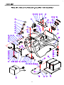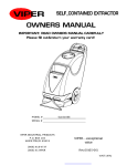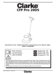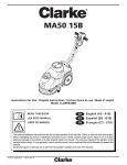
1
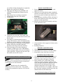
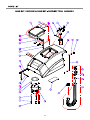
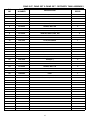
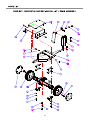
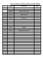
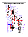
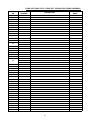
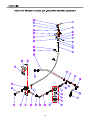
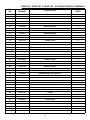
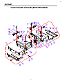
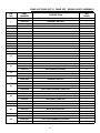
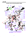
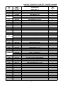
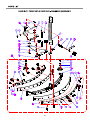
CONGRATULATIONS on your purchase of a
Viper product, and welcome to the V.I.P. family.
We appreciate your business and will do everything in our power to keep you happy with your
purchase for many years to come.
As part of the V.I.P. family, you are entitled to the
best protection by one of the most comprehensive
warranties in the industry.
Thank-you for purchasing Viper products!
TABLE OF CONTENTS
SAFETY PRECAUTIONS
MACHINE COMPONENTS
MACHINE SET UP
MACHINE INSTALLATION
MACHINE OPERATION
TANK DRAINING
BATTERY CHARGING
PREVENTATIVE MAINTENANCE
MACHINE STORAGE
BASIC TROUBLESHOOTING
PARTS BREAKDOWNS AND LISTS
WIRING DIAGRAM
3
4
5
5-6
6
7
7-8
8-9
9
10
11-27
28
2
SAFETY PRECAUTIONS
WHEN SERVICING MACHINE: (con’t)
x Disconnect batteries prior to working
on machine.
x Wear gloves when handling batteries
or battery cables.
x Avoid any contact with battery acid.
x Avoid moving parts. Do not wear
loose fitting clothing while servicing
machine.
This machine is intended for commercial use. It is
constructed for use in an indoor environment and
is not intended for any other use. Use only with
recommended accessories.
All operators shall read, understand and exercise
the following safety precautions:
1) DO NOT OPERATE MACHINE:
x Unless trained and authorized.
x Unless you have read and understand
the operators manual.
x In flammable or explosive areas.
x If not in proper operating condition.
x In outdoor areas.
: Batteries emit hydrogen gas.
Explosion or fire can result from hydrogen gas.
Keep sparks and open flames away! Keep battery
compartment open when charging.
: Flammable materials can cause an
explosion or fire. Do not use flammable materials
in tanks.
2) BEFORE OPERATING MACHINE:
x Make sure all safety devices are in
place and operate properly.
: Flammable materials or reactive
metals can cause explosion or fire. Do not pick up.
3) WHEN USING MACHINE:
x Go slow on inclines and slippery
surfaces.
x Follow all safety guidelines.
x Be very careful when using the
machine in reverse.
x Report and fix any damage to machine
prior to operating it.
4) BEFORE LEAVING OR SERVICING
MACHINE:
x Stop machine on level ground.
x Turn machine off.
5) WHEN SERVICING MACHINE:
x Read operators manual thoroughly
prior to operating or servicing this
machine.
x Use manufacturer supplied or
approved replacement parts.
x Secure machine with wheel blocks
prior to jacking the machine up.
x Use approved jack or hoist to safely
elevate the machine.
3
MACHINE COMPONENTS
1
2
3
4
5
31
7
6
20
21
8
19
30
9
18
29
17
10
16
22
11
15
28
23
14
24
27
25
12
13
26
1. Main power ON/OFF switch
2. Vacuum ON/OFF switch
3. Battery level meter
4. Brush ON/OFF switch
5. Brush pressure meter
6. Solution ON/OFF switch
7. Brush pressure UP/DOWN switch
8. Solution control knob
9. Speed control knob
10. Circuit breakers
11. Recovery tank drain hose
12. Squeegee adjustment nut & shaft
13. Squeegee assembly
14. Scrub head actuator
15. Solution tank level sight tube
16. Console adjustment levers
17. Rear solution fill
18. Reverse switch
19. Squeegee lift lever
20. Control housing
21. Operating triggers
22. Solution tank
23. Rear casters
24. Transport wheels
25. Scrub head
26. Scrub head skirt
27. Skirt housing latch
28. Protective rollers
29. Front solution fill
30. Recovery tank
31. Recovery tank lid
4
3. Check that squeegee is properly installed.
4. Check that brush / pad is properly installed.
MACHINE SET UP & INSTALLATION
UNCRATING MACHINE
Be sure and check packing carton for any damage.
Immediately report any damage to carrier. Check
contents of package to ensure that the following
items are included: Machine, batteries (x2),
squeegee assembly, battery charger, and pad
driver.
INSTALLING PAD DRIVER OR BRUSH
1. Ensure that the machine is turned off
2. Raise the brush head assembly off the floor by
pushing on the brush lift button on the control
console.
3. Open the swing away skirts to gain access to
the brush head assembly.
4. If using a pad driver, first attach the
appropriate pad to the pad driver surface.
5. Mount the pad driver or brush to the drive
motor hub by lining up the three studs with the
three holes in the drive motor hub. Once in
the holes, rotate the driver toward the spring
clip to lock driver into place.
BATTERY CONNECTIONS
The batteries are and charger are shipped
separately and will need to be installed and
connected as shown in the diagram below.
: Batteries emit hydrogen gas.
Explosion or fire can result from hydrogen gas.
Keep sparks and open flames away! Keep battery
compartment open when charging.
1. Be sure power switch is in the “off” position.
2. Open recovery tank to gain access to battery
compartment.
3. Carefully place the two batteries into the
compartment as shown in figure below. Place
the battery brace at the rear of the two
batteries. DO NOT DROP BATTERIES
INTO COMPARTMENT!
4. Connect battery cables to posts in numbered
order as shown in drawing below. (RED to
POSITIVE and BLACK to NEGATIVE)
MOUNTING THE SQUEEGEE
1. Pull back on the squeegee lift lever to raise the
squeegee bracket up.
2. Loosen the two knobs on the squeegee and
slide the squeegee into the slots at the rear of
the squeegee bracket. (the wheels on the
squeegee point to the back)
3. Tighten the knobs securely.
4. Secure the vacuum hose on the pick-up tube of
the squeegee.
RED
BLACK
FILLING THE SOLUTION TANK
1. The Fang 24T / 26T / 28T can be filled in two
different locations:
a. Front fill area for use with a hose or a
bucket.
b. Rear fill area for use with a hose only.
2. Determine which fill area you would like to
use to fill the machine with water.
3. Fill solution tank with up to 17 gallons of
water. (water temperature should not exceed
140° F) The clear tube in the back left of the
machine has gallon markers to help determine
the water level in the solution tank
BATTERY BRACE
C H AR G ER PLU G
5. Apply a coat or protective spray on the cable
connections to prevent battery corrosion.
MACHINE SET UP
PRE-OPERATION CHECKS
1. Sweep or dust mop the surface to be cleaned.
2. Check battery meter to make sure batteries are
fully charged. (see BATTERY CHARGING)
5
10. This machine has reverse. In order to activate
reverse, there is a toggle switch located on the
left side of the control housing. (see machine
components, item #18) The toggle switch
must be pulled backwards and the red
operating triggers must be pressed to activate
reverse motion.
: If you are filling the solution tank with a
bucket, make sure the bucket is clean. This will
prevent debris from clogging the lines or solenoid.
: Do not put any flammable materials
into solution tank. This can cause an explosion or
a fire. Only use recommended cleaning chemicals.
Contact your janitorial supply distributor for
recommendations on proper chemicals.
: Do not keep the machine in the same
position with the pad / brush spinning, or you
could cause damage to the floor.
11. Adjust amount of solution flow by turning the
solution control knob. Turn to the right for
more solution, or turn left for less solution.
(see machine components, item #8)
MACHINE OPERATION
: Do not operate machine unless you
have read and understand this manual.
WHILE OPERATING MACHINE
1. Set control housing to a comfortable operating
height by squeezing together the two thumb
levers directly underneath the housing. (see
machine components, item #16)
2. Lower squeegee assembly to the floor by
releasing the lift lever from its locked position.
(see machine components, item #19)
3. Lower the brush head assembly to the floor by
pushing on the brush lift button on the control
console. (see machine components, item #7)
4. Turn main power to “on” position. (see
machine components, item #1)
5. Turn vacuum motor switch to “on” position.
(see machine components, item #2)
6. Turn the brush motor switch to “on” position.
(see machine components, item #4)
a. Brushes will not spin until the
operating triggers are pulled.
7. Turn the solution switch to “on” position. (see
machine components, item #6)
a. Solution will not begin to flow until
the operating triggers are pulled.
8. To begin scrubbing, pull on one or both of the
red operating triggers. (see machine
components, item #21) When these triggers
are pulled, the brush will begin to spin, the
solution will begin to flow, and the machine
will propel itself.
9. This machine is self-propelled. The speed can
be controlled by a dial located on the right
side of the control housing. (see machine
components, item #9)
1. Occasionally look through the clear recovery
tank lid to see if there is any foam build-up. If
excessive foam is found, add defoamer to the
recovery tank.
: Foam must not enter the float shut-off
screen, or damage can occur to the vacuum motor.
Foam will not activate the machines float shut-off
device.
2. Occasionally view the clear tube at the back
left of the machine to check the amount of
cleaning solution that is left in the machine.
3. Occasionally check the battery level meter.
(see machine components, item #3) When
meter is in the red, recharge the batteries.
: When battery meter is in the red, do
not continue to operate the machine. Battery
damage may result.
4. If the squeegee assembly leaves streaks on the
floor, raise the squeegee off the floor and wipe
the blades down with a damp cloth.
: Do not use your fingers to wipe or
remove debris from the blades, as injury may
occur.
5. When the solution tank runs empty, turn off
the brush switch, solution switch and raise the
brush head. Keep the squeegee down and
continue to vacuum until all the dirty water is
picked up. (see TANK DRAINING section to
learn how to drain recovery and solution tanks)
6
DRAINING THE SOLUTION (CLEAN) TANK
: The brush motors are circuit breaker
protected to protect them from damage. If a
breaker trips, it can’t be reset immediately. You
must first determine what caused the breaker to
trip, and allow the motor to cool down before you
can reset the breaker. The breakers are located on
the back panel of the control housing.
: Anytime scrubbing operation is completed,
the solution tank should be drained and cleaned.
1. Pull down on the clear tube (back left of the
machine) to remove it from the hose barb.
This will allow the solution to flow freely into
a bucket or floor drain.
2. Rinse the solution tank with clean water after
every use. This will help prevent chemical
buildup and clogging of the solution lines.
3. With clean water in solution tank, turn
machine power on, solution switch “on” and
pull the operating triggers. This will allow the
clean water to flush through and clean the
solution plumbing.
4. Once tank is rinsed, flushed and drained,
reconnect the clear tube to the hose barb. Be
sure the tube is pushed all the way up on the
hose barb.
TANK DRAINING
1. Turn the power off on the machine
2. With the squeegee and brush head in their
“up” position, transport machine to approved
area for draining tank(s).
DRAINING THE RECOVERY (DIRTY) TANK
: Anytime scrubbing is completed, or when
refilling solution tank, the recovery tank should be
drained and cleaned.
BATTERY CHARGING
: Use only approved chargers with the
following specifications:
x Automatic shut off circuit
x Deep cycle charging
x Output current of 10 – 20 amps
x Output voltage of 24 volts
: If the recovery tank is not drained
when the solution tank has been refilled, foam or
water may enter the float shut-off mechanism and
cause damage to the vacuum motor.
1. Remove the drain hose from the holder, and
place the drain hose over the floor drain.
Twist off the drain hose plug to begin the
draining process. In order to completely empty
the recovery tank, hinge open the recovery
tank and let it rest on the support stand.
2. Clean the recovery tank after every use. Use a
fresh water hose to rinse out the recovery tank.
Be careful not to spray water into the float
shut-off mechanism.
: For the best machine performance, keep
batteries charged at all times. Do not let them sit
in a discharged condition.
: Batteries are dangerous! Batteries emit
hydrogen gas and an explosion or fire can result.
Keep sparks and fire away from batteries at all
times. When charging the machine, make sure the
battery compartment is left open.
1. Place charger and machine in a well ventilated
area.
2. Turn machine off.
3. Open recovery tank up, exposing battery
compartment
4. Check fluid level in each battery cell. Do not
charge batteries unless fluid is slightly
covering the battery plates. Do not overfill the
batteries. Overfilling may cause the batteries
: If you are storing the machine for any
period of time, always leave the clear recovery
tank lid off the tank so the tank can dry
completely and smell fresh.
3. Replace the drain hose plug tightly as soon as
you are done draining the tank.
7
DAILY MAINTENANCE
1. Remove pad driver / brush and clean with
approved cleaner.
2. Drain recovery and solution tanks completely
and rinse out with clean water. Visually check
the recovery tank for debris and clean out as
necessary.
3. Raise squeegee assembly off floor and wipe it
down with a damp towel. Be sure to store the
squeegee in the up position.
4. Remove the float shut-off assembly and rinse
it out with clean water.
to overflow during charging due to expansion.
Replace the caps prior to charging.
5. Plug approved charger into grounded wall
outlet before plugging the charger into the
machine.
6. Plug charger into red charger receptacle
located in the front left of the battery
7. compartment.
8. Flip up the recovery tank “kick stand” and
gently lay the recovery tank down until it rests
on the stand.
9. The charger will automatically begin to
charger the batteries, and it will automatically
shut down once the batteries are fully charged.
10. Upon completion of charging, first unplug the
charger from the wall outlet, and then
disconnect the charger from the machine.
11. Check the battery level after charging is
complete. If fluid level is low, add distilled
water to bring the fluid level up to the bottom
of the sight tubes. Replace the caps and wipe
the batteries down with a towel.
5. Clean machine with an approved cleaner and a
damp towel.
6. Recharge batteries.
WEEKLY MAINTENANCE
1. Check fluid level in batteries.
2. Check batteries for loose or corroded cables.
3. Keep battery tops clean from corrosion.
MONTHLY MAINTENANCE
1. Check machine for leaks and loose fasteners.
2. Lubricate all grease points and pivot points
with silicon spray and approved grease.
3. Place machine over a floor drain. Flush
solution system by pouring 3 gallons of hot
water and approved alkaline detergent into the
solution tank and running machine (with
solution control on) for 45 seconds. Turn
machine off and let it sit overnight. Then next
day, drain the remaining solution and rinse the
solution tank out with clean water.
PREVENTATIVE MAINTENANCE
: Before performing any maintenance on
the machine, be sure that the power is turned off,
or the batteries are disconnected!
: Repairs are to be completed by
Authorized Service Centers only. Any repairs
completed by unauthorized persons will void the
warranty.
VACUUM MOTOR MAINTENANCE
8
1. Contact your local Viper Distributor for any
motor maintenance.
2. Vacuum motor should have the brushes
checked every 250 hours. Brushes should be
replaced when they are worn to a length of
10mm or less.
caused by freezing temperatures will not be
covered by the warranty.
7. Drain the recovery tank and remove the clear
on the top of the recovery tank so that it can
“breathe” during storage.
8. Drain the solution tank of all fluid.
BATTERY MAINTENANCE
: For the best machine performance, keep
batteries charged at all times. Do not let them sit
in a discharged condition.
: Batteries are dangerous! Batteries emit
hydrogen gas and an explosion or fire can result.
Keep sparks and fire away from batteries at all
times.
: Whenever servicing batteries, be sure
to wear protective gloves. Avoid contact with
battery acid at all times!
1. Always follow the battery charging directions
as outlined in the BATTERY CHARGING
section of this manual.
2. Keep battery tops and terminals free from
corrosion. A strong solution of baking soda
and water is the best way to keep the batteries
corrosion free. DO NOT ALLOW THE
BAKING SODA / WATER SOLUTION TO
ENTER THE BATTERY CELLS.
3. Use a wire brush with the baking soda solution
to properly clean the battery posts and
connections.
4. Check battery connections for wear and loose
terminals. Replace if necessary.
MACHINE STORAGE
1. Always store the machine indoors.
2. Always store the machine in a dry area.
3. Always store the machine in its upright
position.
4. Always store the machine with the pad driver /
brush raised off the floor.
5. Always store the machine with the squeegee
assembly raised off the floor.
6. If storing in an area which may reach freezing
temperatures, be sure to drain all fluids from
the machine prior to storage. Any damage
9
BASIC TROUBLESHOOTING
PROBLEM
No power
CAUSE
Bad batteries
Batteries need to be charged
Loose battery cable
Batteries not connected properly
SOLUTION
Replace batteries
Charge batteries (see Battery Charging)
Tighten loose cable(s)
Follow battery installation instructions
Bad brush switch
Contact Viper Distributor
Brush circuit breaker has tripped
Rectifier has burned out
Bad wiring
Bad brush motor
Carbon brushes worn out
Bad solenoid
Check brush motor for obstructions and reset breaker
Contact Viper Distributor
Contact Viper Distributor
Contact Viper Distributor
Contact Viper Distributor
Contact Viper Distributor
Vacuum motor does
not run
Bad vacuum switch
Contact Viper Distributor
Short run time
Bad wiring
Bad vacuum motor
Carbon brushes worn out
Batteries need to be charged
Batteries need maintenance
Bad cell in battery(s)
Bad charger
Contact Viper Distributor
Contact Viper Distributor
Contact Viper Distributor
Charge batteries (see Battery Charging)
See Battery Maintenance in this manual
Replace batteries
Replace charger
Little or no solution
flow
Bad solution switch
Contact Viper Distributor
Brush motor does
not run
Clogged solution solenoid
Clogged solution filter
Solution line obstructed
Contact Viper Distributor
Remove filter and clean
Remove solution line and clean
Increase flow by twisting solution adjustment knob to the
Solution flow adjustment knob in need
right. Decrease flow by twisting solution adjustment knob
of adjustment
to the left.
Poor water pick up
Squeegee clogged
Clean debris off squeegee with damp towel
Squeegee blades worn
Install new squeegee blades
Confirm that the squeegee assembly is securely fastened
Squeegee not mounted correctly
to the machine and not loose fitting.
Check hose connections and make sure they are firm.
Vacuum hoses have a hole or are loose
Replace hose if damaged.
Vacuum hose may be clogged
Check hose for debris and remove any clog.
Drain hose stopper is loose
Tighten drain plug.
Batteries need to be charged
Charge batteries (see Battery Charging)
Tighten vac motor mounting screws. Do not overtighten or
Vacuum motor is loose
damage will occur.
Recovery tank lid is loose
Confirm the clear recovery tank lid is securely in place.
Drain recovery tank and tilt tank on side. Check the inlet
Recovery tank inlet hole is clogged
hole for debris and remove debris.
Recovery tank is full
Drain recovery tank.
Remove float shut off from inside recovery tank and
Float shut off is clogged
remove any debris.
10
11
FANG 24T,FANG 26T & FANG 28T - SOLUTION TANK ASSEMBLY
DIA
NO
PART
NUMBER
DESCRIPTION
NO
REQ'D
1
VF81405BD
GRIP,HANDLE
1
2
VA13477
SCREW, SELF-TAPPING, ST, M4 X 16
3
3
VV13664
WASHER,PLAIN, M4 X M12 X 1
1
4
VV13604
SCREW, M8 X 20
6
5
VF13519
WASHER,LOCK, M5 X M11 X 28
6
6
VF82154
PLUG,EXPANSION
1
7
VF13535
WASHER,PLAIN, M8 X M20 X 2
8
8
VF81406
BUSHING
1
9
VF81404
SUPPORT,RECOVERY TANK
1
10
VF82029A
BRACKET,VAC TUBE
1
11
VF82032
SPRING
1
12
VF82030
ADAPTER,TUBE
1
13
VF82031A
GASKET,TUBE ADAPTER
1
14
VF82070
LABEL,LEFT
1
15
VF81306
CONNECTOR, 175A
2
16
VF81747
WIRE, #6 X 750
1
17
VF82123
DECAL
1
18
VF13633
SCREW, M6 X 35
2
19
VV13607
WASHER,LOCK, M6
8
20
GT13032
WASHER,PLAIN, M6 X M16 X 1.5
6
21
VF81748
WIRE, #6 X 750
1
22
VF13495
SCREW, M6 X 16
4
23
VF81715
STANDOFF
2
24
VF82067
BRACKET
1
25
VF14232
SCREW, M6 X 10
2
26
VF82078
SCREEN,FILL
1
27
VF13543
SCREW, SELF-TAPPING, ST, M4 X 16
2
28
VF13544
SCREW, SELF-TAPPING, ST, M4 X 10
6
29
VA13483
WASHER,PLAIN, M4 X M9 X 0.8
7
30
VF82081
PLUG,FILL SCREEN
1
31
VF82079
COVER,FILL SCREEN
1
32
VF83101
SOLUTION TANK
1
33
VF82071
LABEL,RIGHT
1
34
VF99001
WHEEL, 4"
2
35
VF83129
BUSHING
2
36
VF13514A
WASHER,PLAIN, M8 X M16.5 X 1
2
37
VF13635
SCREW, M8 X 50
2
38
BAT195I
BATTERY,12V,195AMP HOUR
2
39
VF83111
CASTER, 4"
2
40
VF83140
TRAY,BATTERY
1
41
VF82072A
SPACER,BATTERY
1
42
VF13634
SCREW, M10 X 30
8
43
VF82403
CABLE,BATTERY
1
12
FANG 24T,FANG 26T & FANG 28T - SOLUTION TANK ASSEMBLY
DIA
NO
PART
NUMBER
DESCRIPTION
NO
REQ'D
VF81724
CAPS,BATTERY,BLACK
2
VF81724R
CAPS,BATTERY,RED
2
45
CHRGR18
CHARGER,24V,18AMP
1
46
VF13537
WASHER,PLAIN, M10 X M26 X 2
8
47
VF13518
WASHER,LOCK, M10
8
48
VF14234
SCREW, M8 X 16
2
49
VF13513
NUT, M8
2
50
VF81408
PLATE,LOCK
2
51
VF81416
HOSE BARB
2
52
VF82161
CLAMP (16-25)
1
53
VF81123B
TUBING
1
54
VF14230
SCREW, M5 X 15
3
55
VV13601
WASHER,LOCK, M5
3
56
VF13532
WASHER,PLAIN, M5 X M11 X 2
3
57
VF81202
PLATE,SQGE,LOCK
1
58
VF14235
SCREW, M8 X 35
1
59
VF48216
WASHER,LOCK, M12.7
1
60
VF83124
HANDLE,SQGE,LIFT
1
61
VF82050A
BUSHING
1
62
VF14248
SCREW, M8 X 100
1
63
VA13516
WASHER,PLAIN, M10 X M30 X 1.5
1
44
13
14
FANG 24T, FANG 26T & FANG 28T - RECOVERY TANK ASSEMBLY
DIA
NO
PART
NUMBER
DESCRIPTION
NO
REQ'D
1
VF82010
CLEAR COVER,RECOVERY TANK
1
2
VF82083
DECAL WARNING BATTERY
1
3
VF82009
ELBOW ADAPTOR,FLOAT
1
4
VV13607
WASHER,LOCK, M6
13
5
VF13533
WASHER,PLAIN, M6 X M16 X 2
7
6
VF14233
SCREW, M6 X 20
4
7
VF81504
FLOAT
1
8
VF83102
RECOVERY TANK (24")
1
9
VF13528
WASHER,TOOTH,LOCK, M6
10
VF13495
SCREW, M6 X 16
2
11
VF82028
CABLE
1
12
VF81509
PLUG,EXPANSION
1
13
VF81510-9
STRAP,DRAIN HOSE
1
14
VF81510-2
SLEEVE,DRAIN HOSE
1
15
VF81510A
DRAIN HOSE ASSEMBLY
1
16
VV10113
CLAMP, 2"
1
17
VF83154
DECAL,BATTERY INSTALLATION
1
18
ZD54000
MOTOR,VAC 3 STAGE,24VDC
1
19
VF13502
NUT,LOCK, M6
3
20
VF81508
STUD(24")
3
21
VF13521
NUT,M6
3
22
VF81503
SEAT
1
23
VF14200
SCREW, M6 X 16
9
24
GT13032
WASHER,PLAIN, M6 X M16 X 1.5
9
25
VF82011
HINGE,RECOVERY TANK
1
26
VF82082
LOGO
1
27
VA13477
SCREW, SELF-TAPPING, ST, M4 X 16
4
28
VV13664
WASHER,PLAIN, M4 X M12 X 1
4
29
VF82010A
RUBBER HINGE
1
30
VF82010B
GASKET
1
31
VF82010X
KIT,LID
1
15
2
16
FANG 24T, FANG 26T & FANG 28T - BRUSH LIFT/DRIVE ASSEMBLY
DIA
NO
PART
NUMBER
DESCRIPTION
NO
REQ'D
1
VF82080
HUB CAP
2
2
VF81106
WHEEL, 8"
2
VF81600
TRANSAXLE, 24"
1
ZD72000A
TRANSAXLE MOTOR, 24VDC
1
4
VF81102
BRACKET,TRANSAXLE MOUNT
2
5
VF13537
WASHER,PLAIN, M10 X M26 X 2
6
6
VF13518
WASHER,LOCK, M10
6
7
VF13636
SCREW, M10 X 45
4
8
VF13634
SCREW, M10 X 30
2
9
VF13502
NUT,LOCK, M6
8
10
VF13533
WASHER,PLAIN, M6 X M16 X 2
8
11
VF81103
SPACER
4
12
VF82016A
BUSHING
2
13
VF13538
WASHER,PLAIN, M12 X M22 X 2
4
14
VF83136
BRACKET,LIFT DUAL MOTOR
1
15
VF83139
PIN, M10 X 30
2
16
VF14084
PIN,COTTER, M3.2 X 24
2
17
VF81301
ACTUATOR
1
18
VF13519
WASHER,LOCK, M8
4
19
VV13604
SCREW, M8 X 20
4
20
VF13535
WASHER,PLAIN, M8 X M20 X 2
4
21
VF83126
BRACKET,CABLE GUIDE
1
22
VF83135
BRACKET,ACTUATOR
1
23
VF83115
PLATE
1
24
VF14247
SCREW, M12 X 25
2
25
VF81101A
PLATE,BASE TRANSAXLE
1
26
VF13501
NUT,LOCK, M12
2
3
17
18
FANG 24T,FANG 26T & FANG 28T - BRUSH/PAD DRIVE ASSEMBLY
DIA
NO
PART
NUMBER
DESCRIPTION
NO
REQ'D
1
VF83112A
BLOCK,GUIDE
1
2
VV20274B
WASHER,PLAIN, M13 X M39 X 2
1
3
VA13400
WASHER,PLAIN, M5 X M11 X 1
4
4
GT13022
NUT,LOCK, M5
4
5
VF14234
SCREW, M8 X 16
1
6
VF13519
WASHER,LOCK,M8
9
7
VF13542
WASHER,PLAIN, M8 X M26 X 2
1
8
VF83116A
SUPPORT PLATE,SKIRT
1
9
VF13535
WASHER,PLAIN, M8 X M20 X 2
8
10
VF81114
BRACKET,SPRING
1
11
VF83117
SPRING
1
12
VA14303
PIN, M4 X 40
1
13
VF83113A
BRACKET,SPRING MOUNT
1
VF81112
BRACKET,MOTOR MOUNT (FANG24T & FANG26T)
1
14
VF83205
BRACKET,MOTOR MOUNT ( FANG28T)
1
15
VF81122
TUBING, 150mm
1
16
VF82040
HOSE BARB,TEE
1
17
VF81121
TUBING, 120mm
1
18
VF82148
CLAMP, 16mm
2
19
VF14225A
SCREW, M6 X 40
6
20
VF83133
STUD
6
VF81105
PAD DRIVER, 11" (FANG24T)
2
VF83128
PAD DRIVER, 12" (FANG26T)
2
VF83207
PAD DRIVER,13" (FANG28T)
2
22
VF13502
NUT,LOCK, M6
6
23
VF83118
SPACER
2
24
VF99003A
BIG MOUTH
2
25
VA13484
SCREW,SELF-TAPPING,ST, M4 X 12
6
26
MF-VF002-4A
SCREW,SELF-TAPPING, 1/4" - 1"
6
21
27
VF14241
SCREW, 5/16" - 1"
2
28
VV20298
WASHER,LOCK, 5/16"
2
29
VF82058
WASHER
2
30
VF83130A
PLATE, DRIVE, ASSY
1
31
VF83130
PLATE,DRIVE
2
32
VF83134
STOP,DRIVE RELEASE
2
33
VF83132
SPRING
2
34
VF83131
CLAMP,BRUSH PLATE
2
35
VV13601
WASHER,LOCK, M5
8
36
VF13545
SCREW,SELF-TAPPING,ST,M5 X 10
8
37
VV13604
SCREW, M8X20
8
38
VF14242
SCREW, 3/8" - 1"
8
39
VV13620
WASHER,LOCK, 3/8"
8
40
VF13537
WASHER,PLAIN,M10 X M26 X 2
8
41
VF83114
PIN, M16 X 42
1
42
ZD45407
KEY, 6.35 X 25
2
43
ZD45000
BRUSH MOTOR,24VDC, .75HP
2
44
VF14230
SCREW, M5 X 15
4
19
20
FANG 24T, FANG 26T & FANG 28T - SOLUTION CONTROL ASSEMBLY
DIA
NO
PART
NUMBER
DESCRIPTION
NO
REQ'D
1
VF14245
SCREW, M5 X 6
2
2
VF82036
SHAFT
1
3
VV13650
SCREW, M4 X 10
1
4
VF13532
WASHER,PLAIN, M5
4
5
VV13601
WASHER,LOCK, M5
4
6
VF14230
SCREW, M5 X 15
2
7
VF13536
WASHER,PLAIN, M9.8 X M16 X 1
2
8
VF82075
NUT, 3/8"
2
9
VF83121
CABLE,SOLENOID
1
10
VF82148
CLAMP, 16mm
14
11
VF82040
HOSE BARB,TEE
1
12
VF81134
TUBING, 50mm
2
13
VF82042
ELBOW
2
14
VF81124
TUBING, 115mm
1
15
VF81403A
ELBOW,SOLUTION TANK
2
16
VF81780
TIE
2
17
VF82168-1
HOSE BARB, FILTER
2
18
VF82168-3
SEAT,FILTER
1
19
VF82168-4
SCREEN,80SS,FILTER
1
20
VF82168-5
GASKET,FILTER
1
21
VF82168-2
COVER,FILTER
1
22
VF82168
FILTER, ASSY
1
23
VF81125
TUBING, 200mm
1
24
VF81126
TUBING, 80mm
1
25
VF13495
SCREW, M6 X 16
4
26
VF13533
WASHER,PLAIN, M6 X M16 X 2
4
27
VF81127
TUBING, 65mm
1
28
VF82033-24
SOLUTION VALVE SOLENOID,24VDC
1
29
VV13607
WASHER,LOCK, M6
2
30
VF83120
BRACKET,SOLENOID
1
31
VF13502
NUT,LOCK, M6
2
32
VF81128
TUBING, 320mm
1
33
VV20509
SCREW,M5X10
2
34
VF81118
CLAMP
2
35
VF13540
WASHER,WAVE, M12
1
36
VF82037
BRACKET,DRAIN HOSE & VALVE
1
37
VF82069
LABEL,VALVE
1
38
VF82074
BUSHING
1
39
VF82038
KNOB,VALVE ADJUST
1
21
22
FANG 24T,FANG 26T & FANG 28T - BRUSH SKIRT ASSEMBLY
DIA
NO
PART
NUMBER
DESCRIPTION
NO
REQ'D
VF81109
BUMPER (FANG 24T)
1
VF83105
BUMPER (FANG 26T)
1
VF83203
BUMPER (FANG 28T)
1
2
VF13495
SCREW, M6 X 16
8
3
VV13607
WASHER,LOCK, M6
8
4
VF13533
WASHER,PLAIN, M6
8
5
VF83107
BRACKET,SKIRT MOUNT
2
6
VF83108
PIN,SKIRT
2
7
VF82013
WHEEL, 3"
2
1
8
VF82055
BUSHING
2
9
VF13514A
WASHER,PLAIN, M8 X M16.5 X 1
2
10
VF14236
SCREW, M8 X 40
2
11
VA13474
SCREW, M5 X 16
18
12
VF13550
WASHER,PLAIN, M5 X M25 X 1.5
4
VF81130
CLAMP,BUMPER (FANG 24T)
2
VF83151
CLAMP,BUMPER (FANG 26T)
4
VF83204
CLAMP,BUMPER (FANG 28T)
2
VA13400
WASHER,PLAIN, M5 X M11 X 1
14
VF81117
GRIP,BUMPER (FANG 24T)
2
VF83147
GRIP,BUMPER (FANG 26T)
4
VF83212
GRIP,BUMPER (FANG 28T)
2
VF81131
CLAMP,BUMPER (FANG 24T)
2
VF83213
CLAMP,BUMPER (FANG 28T)
2
VF81109A
BUMPER (FANG 24T)
1
VF83105A
BUMPER (FANG 26T)
1
VF83203A
BUMPER (FANG 28T)
1
VF81108R
RIGHT SKIRT,ASSEMBLY (FANG 24T)
1
VF83104R
RIGHT SKIRT,ASSEMBLY (FANG 26T)
1
VF83202R
RIGHT SKIRT,ASSEMBLY (FANG 28T)
1
VV20519
SCREW, M4 X 8
4
VF81108
SKIRT,RIGHT (FANG 24T)
1
VF83104
SKIRT,RIGHT (FANG 26T)
1
VF83202
SKIRT,RIGHT (FANG 28T)
1
13
14
15
16
17
18
19
20
21
VF83109
LATCH,HOOD
1
22
VV20291
WASHER,LOCK, M4
4
VF81107
SKIRT,LEFT (FANG 24T)
1
VF83103
SKIRT,LEFT (FANG 26T)
1
VF83201
SKIRT,LEFT (FANG 28T)
1
VF83142
BLOCK,SKIRT
2
VF81107L
LEFT SKIRT,ASSEMBLY (FANG 24T)
1
VF83103L
LEFT SKIRT,ASSEMBLY (FANG 26T)
1
VF83201L
LEFT SKIRT,ASSEMBLY (FANG 28T)
1
23
24
25
23
24
FANG 24T, FANG 26T & FANG 28T - CONTROL HOUSING
DIA
NO
PART
NUMBER
DESCRIPTION
NO
REQ'D
1
2
3
4
5
VF13491
VF14122
VF14121
VF13502
GT13032
VF81781
VF81781-X
VF81726A
VF81734
VF83149
VF82301
VF81713
VF82305
VF14078
VA50477
VF81718
VF82313
VF13495
VF81719
VF83137A
VF81708A
VF83138A
VF83209A
VF81721
VF81727
VF81725
VF14200
VF81730
VF81709
VF81716
VF81710
VF81729
VF82316
VF81739-24T
VF81115
VF83145
VF83210
VF83148
VF82303A
VF81703
VF82312
VF99012
VF82107BD
VF81711
VF81712
VF13514A
VF82106BD
VF14212
VF13511
VF44203
VF81707
VV13652
VF81714
VF82153
VF82160
VF81744B
VF81722
SCREW, M4 X 12
WASHER,PLAIN, M10 X M20 X 2
SCREW, M10 X 65
NUT,LOCK, M6
WASHER,PLAIN, M6
DIODE, 400V
DIODE WITH ENDS
SOLENOID, 24V
BREAKER,CIRCUIT, 35 AMP
LABEL,CIRCUIT BREAKER
HOUSING,CONTROL
BUSHING
LABEL,SPEED CONTROL
SCREW,M3 X 10
WASHER,PLAIN, M3 X M10 X 1
LIGHTS,BATTERY CAPACITY
GASKET
SCREW, M6 X 16
SPACER
PANEL,SWITCH (24")
LABEL,SWITCH (FANG 24T)
LABEL,SWITCH (FANG 26T)
LABEL,SWITCH (FANG 28T)
SWITCH,LIGHTED ROCKER
GAUGE,BRUSH PRESSURE
SWITCH,BRUSH LIFT
SCREW, M6 X 16
KNOB,SPEED CONTROL
PIN,HANDLE LOCK
SPRING
PIN,HANDLE ADJUSTMENT
POTIENTIOMETER, 4.7K
PLATE
SPEED CONTROL,BOARD
SERIAL TAG (FANG 24T)
SERIAL TAG (FANG 26T)
SERIAL TAG (FANG 28T)
LABEL,CIRCUIT BREAKER
PANEL,CONTROL HOUSING
BATTERY CAPACITY CONTROL,BOARD
GASKET
BREAKER,CIRCUIT, 12 AMP
HANDLE,RIGHT
BOLT,SHOULDER, M8 X 15 X M6
SPRING
WASHER,PLAIN, M8 X M16.5 X 1
HANDLE,LEFT
SCREW, M3X25
WASHER,TOOTH, M3
SWITCH ASSY
BRACKET,SWITCH (24")
NUT,LOCK, M3
TUBE,HANDLE,ADJUSTMENT
SWITCH,KEY
LABEL,KEY SWITCH
STRAIN RELIEF,CORD
SWITCH,TOGGLE
7
2
2
10
6
3
3
3
3
1
1
2
1
6
6
1
1
4
6
1
1
1
1
4
1
1
12
1
2
1
2
1
1
1
1
1
1
1
1
1
1
1
1
2
1
2
1
2
2
1
1
2
1
1
1
1
1
6
7
8
9
10
11
12
13
14
15
16
17
18
19
20
21
22
23
24
25
26
27
28
29
30
31
32
33
34
35
36
37
38
39
40
41
42
43
44
45
46
47
48
49
50
51
52
25
26
FANG 24T,FANG 26T & FANG 28T - SQUEEGEE ASSEMBLY
DIA
NO
PART
NUMBER
DESCRIPTION
NO
REQ'D
1
VF13501
NUT,LOCK, M12
3
2
VF13538
WASHER,PLAIN, M12 X M26 X 2
1
3
VF83122
MOUNT,PIVOT
1
4
VF13637
SCREW, M12 X 130
1
5
VF14238
SCREW, M12 X 30
2
6
VF82016A
BUSHING
2
7
VF81243
CABLE,SQGE,LIFT (24")
1
8
VF82112
BUSHING
1
9
VF81203A
HOSE
1
10
VF83150
HOLDER,"U" HOSE
1
11
VF83144
SPRING
1
12
VF82047
SHAFT
1
13
VF83125
BRACKET,SPRING
1
14
VF81210
KNOB, M8
3
15
VF14236
SCREW,M8 X 40
4
16
VF13514A
WASHER,PLAIN, M8 X M16.5 X 1
2
17
VF82055
BUSHING
2
18
VF82013
WHEEL, 3"
2
VF81201
HOUSING,SQUEEGEE (FANG 24T & 26T)
1
VF81231
HOUSING,SQUEEGEE (FANG 28T)
1
19
20
VF81206
BLADE,SQUEEGEE,REAR,PU (FANG 24T & 26T)
1
VF81216
BLADE,SQUEEGEE,REAR,NEOPRENE (FANG 24T & 26T)
1
VF81237
BLADE,SQUEEGEE,REAR,PU (FANG 28T)
1
VF81235
BLADE,SQUEEGEE,REAR,NEOPRENE (FANG 28T)
1
21
VF81218A
LATCH,HOOD
1
22
VF81209
HOOK,REAR SQUEEGEE BACKUP ADJUSTMENT
1
23
VF14310
SCREW, M5 X 70
1
24
VF81208A
RIVET, M4 X 5
2
25
GT13022
NUT,LOCK, M5
1
26
VF81222
BOLT,SHOULDER, 5/16" X 1.25"
3
27
VF81219
WHEEL, 2"
3
28
VF13535
WASHER,PLAIN, M8 X M20 X 2
3
29
VV20203
NUT,LOCK, 5/16"
3
VF81214
BACKUP STRIP,SQUEEGEE,REAR (FANG 24T & 26T)
1
VF81233
BACKUP STRIP,SQUEEGEE,REAR (FANG 28T)
1
VF81214A
KIT,BACKUP STRIP (FANG 24T & 26T)
1
VF81233A
KIT, BACKUP STRIP (FANG 28T)
1
VF81205
BLADE,SQUEEGEE,FRONT,PU (FANG 24T & 26T)
1
VF81215
BLADE,SQUEEGEE,FRONT,NEOPRENE (FANG 24T & 26T)
1
VF81236
BLADE,SQUEEGEE,FRONT,PU (FANG 28T)
1
VF81234
BLADE,SQUEEGEE,FRONT,NEOPRENE (FANG 28T)
1
VF81213
BACKUP STRIP,SQUEEGEE,FRONT (FANG 24T & 26T)
1
VF81232
BACKUP STRIP,SQUEEGEE,FRONT (FANG 28T)
1
30
31
32
33
34
VF82121
KNOB, M6
6
35
VF13502
NUT,LOCK, M6
1
36
VF83123
BRACKET,SQGE,MOUNT
1
37
VF13521
NUT, M6
1
38
39
VF13539
WASHER,PLAIN, M12 X M32 X 2
4
VF81008A
SQUEEGEE ASSY (FANG 24T & 26T)
1
VF81008B
SQUEEGEE ASSY (FANG 28T)
1
27
28